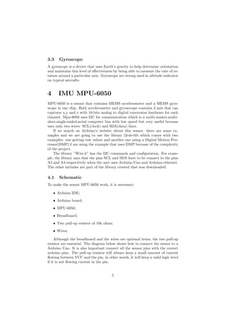
This document provides a tutorial on using an Arduino board with an MPU-6050 inertial measurement unit (IMU) sensor and nRF24L01 wireless communication module. It describes the history and software of Arduino, details of IMUs and the specific MPU-6050 sensor, schematics and code for reading data from the MPU-6050 over I2C, and schematics and code for wireless data transmission with the nRF24L01 module. The goal is to integrate these components to create a functioning motion sensing and wireless data transmission project using the Arduino platform.
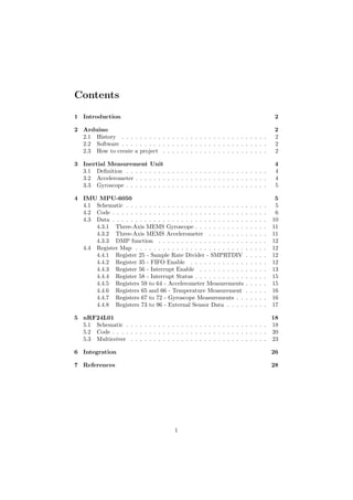
![Those control variables are very important to make the MPU works and
each one has a di↵erent function.
1 bool dmpReady = false;
2 uint8_t mpuIntStatus;
3 uint8_t devStatus;
4 uint16_t packetSize;
5 uint16_t fifoCount;
6 uint8_t fifoBuffer[64];
The meaning of each variable is:
• dmpReady is true if DMP initialization was successful.
• mpuIntStatus holds the actual interrupt status byte from MPU.
• devStatus returns the status after each device operation (0 = success, !0
= error).
• fifoCount is the DMP packet size(default is 42 bytes).
• fifoBu↵er[64] is the FIFO storage bu↵er.
In the function setup() is important to initialize the library wire and set up
the i2c speed. Every device has a maximum speed and this information is found
in the datasheet. In our case, the maximum speed is 400KHz. Make sure the
processor used is 16MHz, otherwise the speed has to be decreased to 200KHz.
1 #if I2CDEV_IMPLEMENTATION == I2CDEV_ARDUINO_WIRE
2 Wire.begin();
3 TWBR = 24;
4 #elif I2CDEV_IMPLEMENTATION == I2CDEV_BUILTIN_FASTWIRE
5 Fastwire::setup(400, true);
6 #endif
After initialize the i2c, it is time to start the MPU and test if the device is
connect to the Arduino. The commands below are responsible for that:
1 mpu.initialize();
2 Serial.println(mpu.testConnection());
Note: The library used has a file called ”MPU6050.cpp” which initializes
the sensor. The following code is located in this file.
1 void MPU6050::initialize()
2 {
7](https://image.slidesharecdn.com/13c6ec44-6021-473c-90fc-15e33941ed9f-160212181646/85/MPU-6050_RF24L01-8-320.jpg)
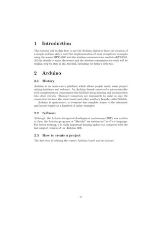
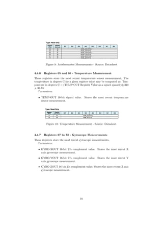
![SMPLRTDIV is a 8-bit unsigned value.
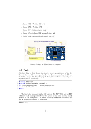
As expected, the FIFO has a bu↵er size and it is impossible knowing how
to deal with it. The line below is getting the the number of bytes stored in
the FIFO bu↵er. This number is in turn the number of bytes that can be read
from the FIFO bu↵er and it is directly proportional to the number of samples
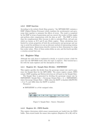
available given the set of sensor data bound to be stored in the FIFO. The
program will return the FIFO bu↵er size.
1 fifoCount = mpu.getFIFOCount()
The following code shows that the command ”mpu.getFIFOCount()” comes
from the file ”MPU6050.cpp” that comes from the library.
1 uint16_t MPU6050::getFIFOCount()
2 {
3 I2Cdev::readBytes(devAddr, MPU6050_RA_FIFO_COUNTH, 2, buffer);
4 return (((uint16_t)buffer[0]) << 8) | buffer[1];
5 }
Since the moment the program knows the size of the FIFO, it is possible
making a conditional that will delete the oldest data in the FIFO if an overflow
happen. If not, the fifobu↵er will be read and the data will be available.
The FIFO R-W register is the register is used to read and write data from
the FIFO bu↵er. Data is written to the FIFO in order of register number (from
lowest to highest). If all the FIFO enable flags (see below) are enabled and all
External Sensor Data registers (Registers 73 to 96) are associated with a Slave
device, the contents of registers 59 through 96 will be written in order at the
Sample Rate.
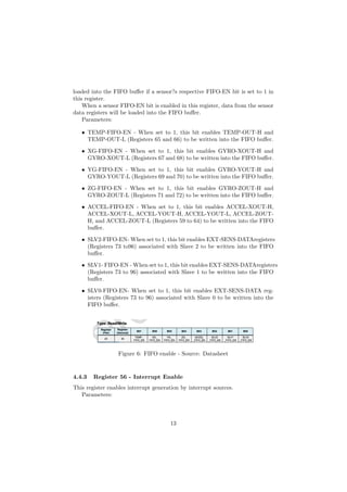
The contents of the sensor data registers (Registers 59 to 96) are written
into the FIFO bu↵er when their corresponding FIFO enable flags are set to
1 in FIFO-EN (Register 35). An additional flag for the sensor data registers
associated with I2C Slave 3 can be found in I2C-MST-CTRL (Register 36).
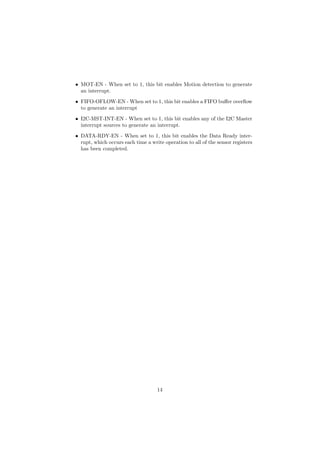
If the FIFO bu↵er has overflowed, the status bit FIFO-OFLOW-INT is au-
tomatically set to 1. This bit is located in INT-STATUS (Register 58). When
the FIFO bu↵er has overflowed, the oldest data will be lost and new data will
be written to the FIFO.
If the FIFO bu↵er is empty, reading this register will return the last byte
that was previously read from the FIFO until new data is available. The user
should check FIFO-COUNT to ensure that the FIFO bu↵er is not read when
empty.
1 if ((mpuIntStatus & 0x10) || fifoCount == 1024)
2 {
3 mpu.resetFIFO();
4 }
9](https://image.slidesharecdn.com/13c6ec44-6021-473c-90fc-15e33941ed9f-160212181646/85/MPU-6050_RF24L01-10-320.jpg)
![5 else if (mpuIntStatus & 0x02)
6 {
7 while (fifoCount < packetSize) fifoCount = mpu.getFIFOCount();
8 mpu.getFIFOBytes(fifoBuffer, packetSize);
9 fifoCount -= packetSize;
10
11 #ifdef OUTPUT_READABLE_YAWPITCHROLL
12 mpu.dmpGetQuaternion(&q, fifoBuffer);
13 mpu.dmpGetGravity(&gravity, &q);
14 mpu.dmpGetYawPitchRoll(ypr, &q, &gravity);
15 Serial.print("yprt");
16 Serial.print(ypr[0] * 180/M_PI);
17 Serial.print("t");
18 Serial.print(ypr[1] * 180/M_PI);
19 Serial.print("t");
20 Serial.println(ypr[2] * 180/M_PI);
21 #endif
22 }
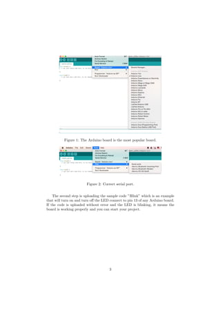
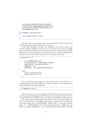
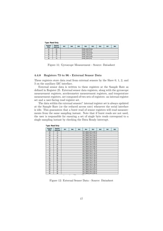
Note: To prevent FIFO overflow, do not execute the command delay(). It
is also important to make sure that the sample rate has more or less the same
speed than the FIFO output.
4.3 Data
More important than get the data from the sensor, it is get a reliable data. The
code below is calibrating the sensor with the right o↵set of each axis: x,y and
z. Every sensor has di↵erent o↵sets, so it is essential to find those values using
another example that can be MPU6050.raw.ino that comes in the library file
too.
1 mpu.setXGyroOffset(220);
2 mpu.setYGyroOffset(76);
3 mpu.setZGyroOffset(-85);
4 mpu.setZAccelOffset(1788);
The scale factor of accelerometers is calibrated at the factory and is nomi-
nally independent of supply voltage. Before we start using the MEMS we should
calibrate using the code above because the raw values change a lot. After we
get the o↵sets from the calibration, we have to write them in the code above.
For reliable o↵sets, the device has to be placed on a flat surface.
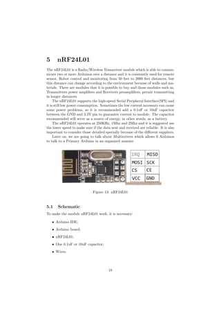
1 // MPU-6050 Short Example Sketch
2 // By Arduino User JohnChi
3 // August 17, 2014
4 // Public Domain
10](https://image.slidesharecdn.com/13c6ec44-6021-473c-90fc-15e33941ed9f-160212181646/85/MPU-6050_RF24L01-11-320.jpg)
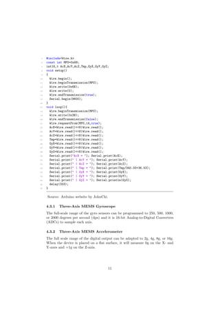
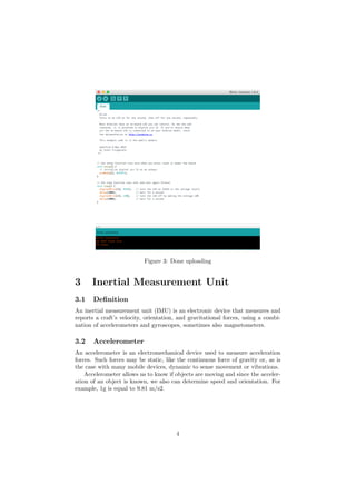
![1 radio.begin();
2 radio.openWritingPipe(pipe);
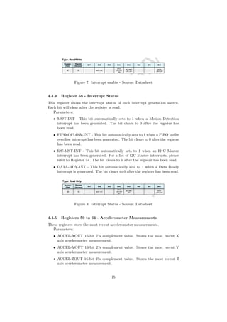
Then, the next function is the loop() which will be very simple too. We just
have to write the data we want to send to the receiver. In this example, we are
sending an array of three elements.
1 int test[3];
2 test[0] = 10;
3 test[1] = 20;
4 test[2] = 30;
5 radio.write( test, sizeof(test));
Now, we will se how to program the function setup() of the receiver mode.
1 radio.openReadingPipe(1,pipe);
2 radio.startListening();;
The nRF24L01 supports six pipes for reading, so it is important to define
each one we will use. In this example, the pipe 1 is the first. Before reading, we
must use the function startListening();
In the function loop(), we will verify if there is a connection, then the pro-
gram will be ready to receive the 3 elements we are waiting.
1 int text[3];
2 if ( radio.available() )
3 {
4 bool done = false;
5 while (!done)
6 {
7 done = radio.read( text, sizeof(text) );
8 Serial.print("Number: ");
9 Serial.print(text[0]);
10 Serial.print("Number: ");
11 Serial.print(text[1]);
12 Serial.print("Number: ");
13 Serial.print(text[2]);
14 }
15 }
16 else
17 {
18 Serial.println("No radio available");
19 }
20 }
21](https://image.slidesharecdn.com/13c6ec44-6021-473c-90fc-15e33941ed9f-160212181646/85/MPU-6050_RF24L01-22-320.jpg)
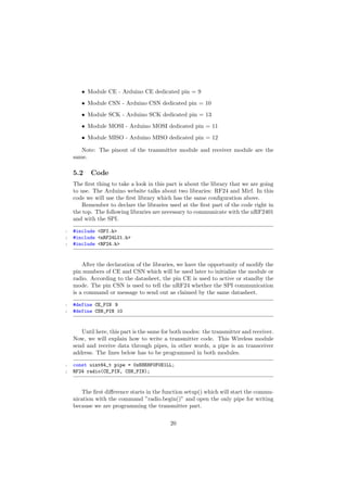
![The entire Transmitter code is
1 #include <SPI.h>
2 #include <nRF24L01.h>
3 #include <RF24.h>
4
5 #define CE_PIN 9
6 #define CSN_PIN 10
7
8 const uint64_t pipe = 0xE8E8F0F0E1LL; // Define the transmit pipe
9
10 RF24 radio(CE_PIN, CSN_PIN); // Create a Radio
11 int test[3];
12 void setup()
13 {
14 radio.begin();
15 radio.openWritingPipe(pipe);
16 }
17
18 void loop()
19 {
20 test[0] = 10;
21 test[1] = 20;
22 test[2] = 30;
23 radio.write( test, sizeof(test));
24 }
The entire Receiver code is
1 #include <SPI.h>
2 #include <nRF24L01.h>
3 #include <RF24.h>
4
5 #define CE_PIN 9
6 #define CSN_PIN 10
7
8 const uint64_t pipe = 0xE8E8F0F0E1LL;
9
10 RF24 radio(CE_PIN, CSN_PIN);
11 int text[3];
12 void setup()
13 {
14 radio.openReadingPipe(1,pipe);
15 radio.startListening();;
16 }
17
18 void loop()
22](https://image.slidesharecdn.com/13c6ec44-6021-473c-90fc-15e33941ed9f-160212181646/85/MPU-6050_RF24L01-23-320.jpg)
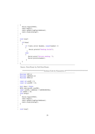
![19 {
20 if ( radio.available() )
21 {
22 bool done = false;
23 while (!done)
24 {
25 done = radio.read( text, sizeof(text) );
26 Serial.print("Number: ");
27 Serial.print(text[0]);
28 Serial.print("Number: ");
29 Serial.print(text[1]);
30 Serial.print("Number: ");
31 Serial.print(text[2]);
32 }
33 }
34 else
35 {
36 Serial.println("No radio available");
37 }
38 }
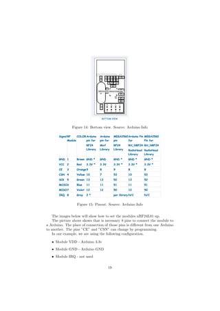
5.3 Multiceiver
MultiCeiver is a feature used in RX mode that contains a set of six parallel
data pipes with unique address. A data pipe is a logical channel in the phys-
ical RF channel. Each data pipe has its own physical address decoding in the
NRF24L01+.
Figure 16: MultiCeiver schematic. Source: Datasheet
Both modes have di↵erents codes from the first and second example one
showed. ***************************Arduino Code for Receiver*******************************
23](https://image.slidesharecdn.com/13c6ec44-6021-473c-90fc-15e33941ed9f-160212181646/85/MPU-6050_RF24L01-24-320.jpg)
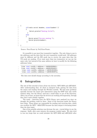
![1 include <SPI.h>
2 include <nRF24L01.h>
3 include <RF24.h>
4
5 const int pinCE = 9;
6 const int pinCSN = 10;
7 RF24 radio(pinCE, pinCSN);
8 const uint64_t rAddress[] = {0xB00B1E50D2LL, 0xB00B1E50C3LL};
9 int number = 0;
10 void setup()
11 {
12 Serial.begin(57600);
13 radio.begin();
14 radio.openReadingPipe(1,rAddress[0]);
15 radio.openReadingPipe(2,rAddress[1]);
16 radio.startListening();
17 }
18
19 void loop()
20 {
21 byte pipe = 0;
22
23 while(radio.available(&pipe))
24 {
25 radio.read( &number, sizeof(number));
26 Serial.print("Transmitter number ");
27 Serial.println(pipe);
28 Serial.print("Number: ");
29 Serial.println(number);
30 Serial.println();
31 }
32 }
Source: ForceTronic by Neil ForceTronic.
***************************Arduino Code for Transmitter 1****************************
1 #include <SPI.h>
2 #include <nRF24L01.h>
3 #include <RF24.h>
4
5 const int pinCE = 9;
6 const int pinCSN = 10;
7
8 bool done = false;
9 RF24 radio(pinCE, pinCSN);
10 const uint64_t wAddress = 0xB00B1E50D2LL;
11 int number = 10;
12 void setup()
24](https://image.slidesharecdn.com/13c6ec44-6021-473c-90fc-15e33941ed9f-160212181646/85/MPU-6050_RF24L01-25-320.jpg)

![7 References
[1] Arduino O cial.
[2] MPU-6050 Datasheet.
[3] Gyroscopes and Accelerometers.
[4] DMP data.
[5] Nrf24L01-2.4GHz-Arduino O cial.
[6] Nrf24L01-2.4GHz Datasheet.
[7] Nrf24L01-2.4GHz-HowToWork.
[8] GithubRF24.
[9] Multiceiver.
28](https://image.slidesharecdn.com/13c6ec44-6021-473c-90fc-15e33941ed9f-160212181646/85/MPU-6050_RF24L01-29-320.jpg)