Download as PDF, PPTX

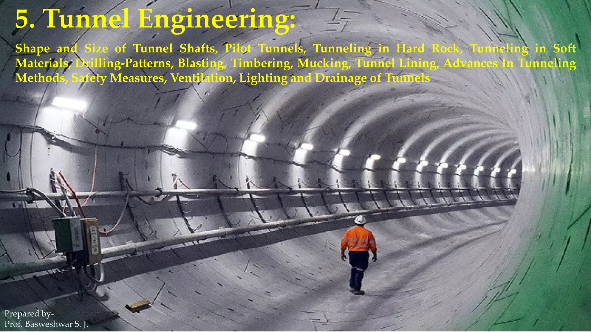
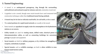

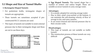
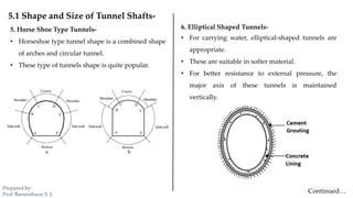

The document outlines various aspects of tunnel engineering, including tunnel shapes, sizes, and methods of construction for both hard rock and soft materials. It describes different tunnel shapes such as polycentric, circular, rectangular, and egg-shaped, along with their advantages and disadvantages. Additionally, it covers tunneling techniques, pilot tunnels, and drilling patterns used in the excavation process.


