Downloaded 424 times
![USN 06ME63
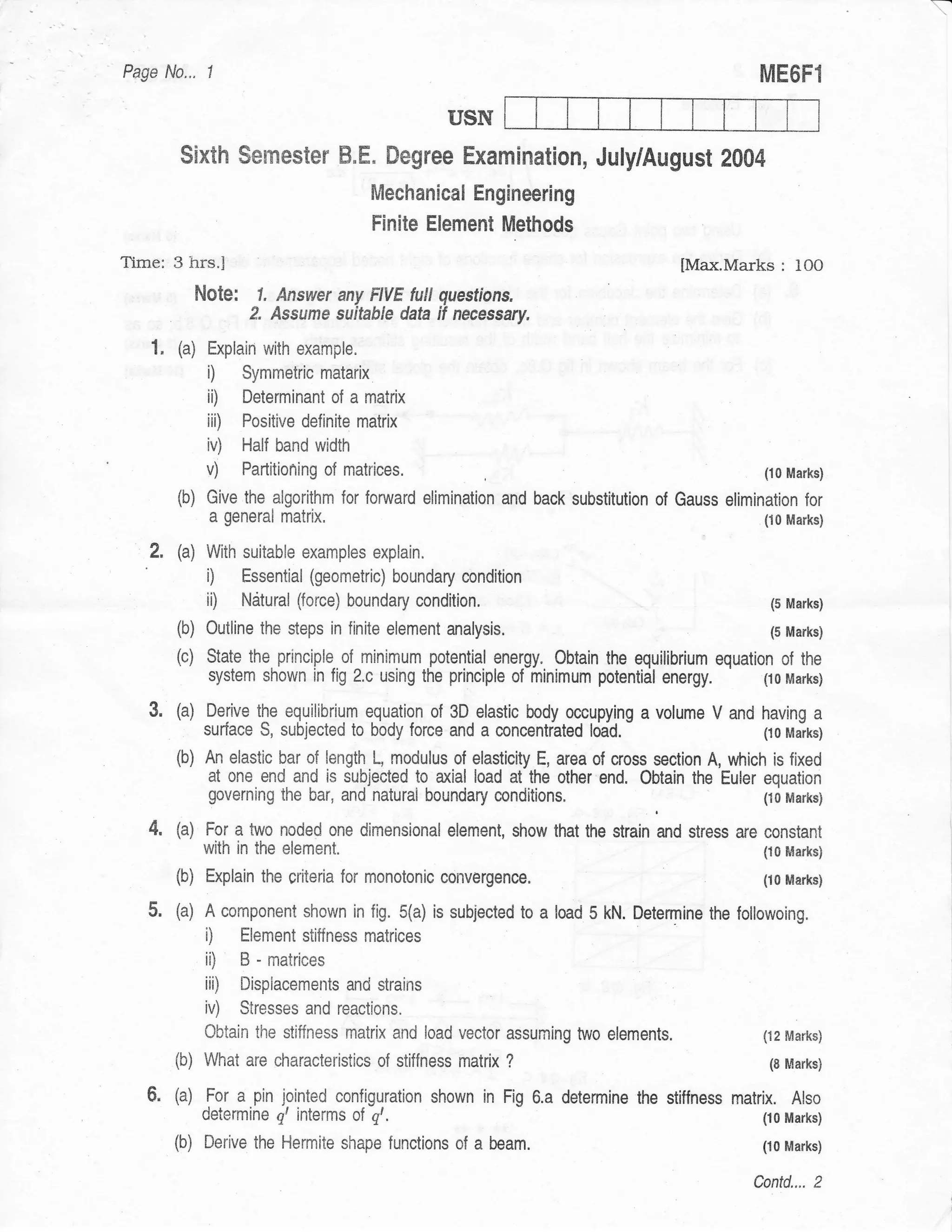
Sixth Semester B.E. f)egree Examination, December 2Ol2
Modeling and Finite Element Analysis
Tirne: 3 hrs. Max. Marks:100
Note: Answer FIVE full questions, selecting
at leust TWO questions from eoch part.
!
.! PART _ A
a
u
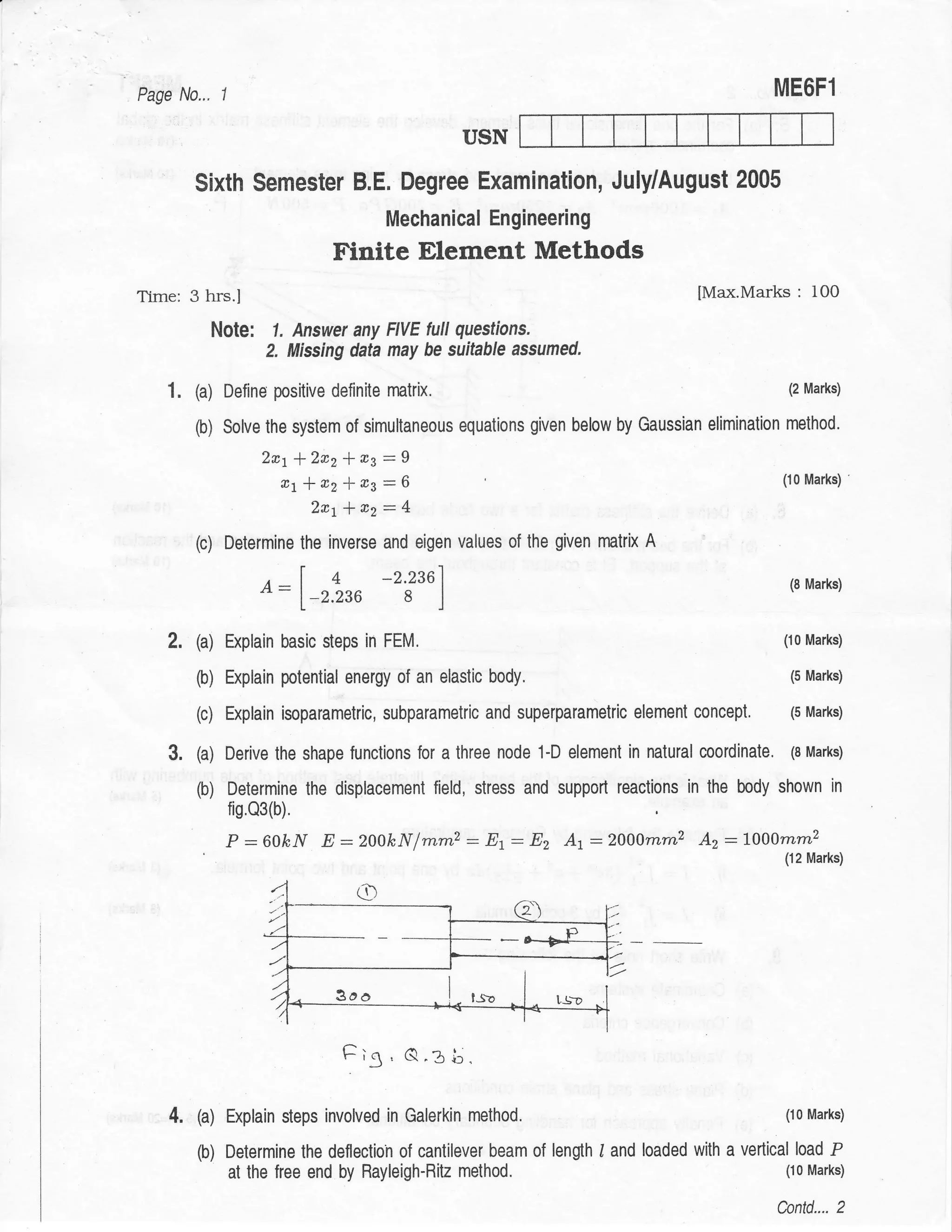
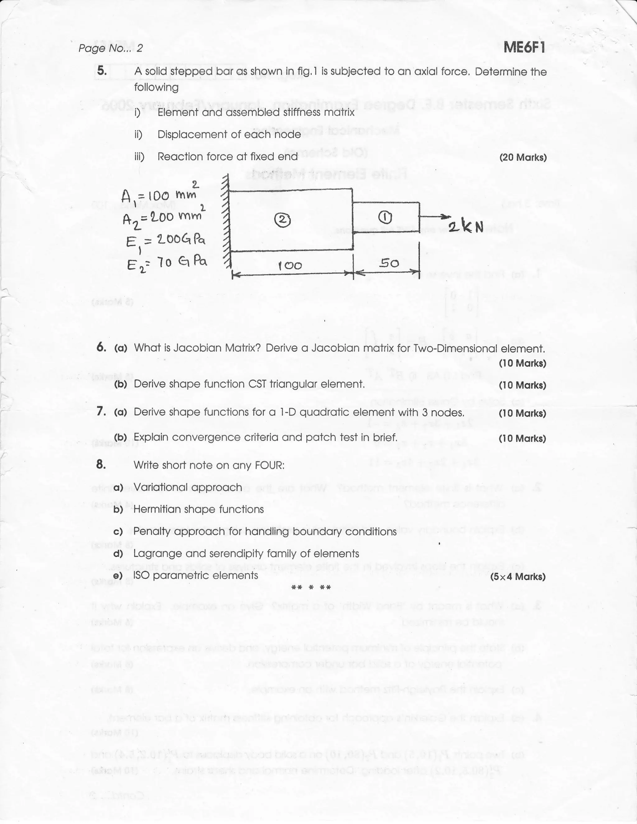
e la. Using Rayleigh-Ritz method, derive an expression for maximum det.lection of the simply
= b. supported beam with point load P at centre. Use trigonometric function. (08 Marks)
a Solve the following system of simultaneous equations by Gauss elimination method.
O X-l Y 'l Z:9
aX, x-2y+32:8
=D- 2x+ Y - z:3 (08 Marks)
c. Explain the principle of minimum potential energy and principle of virtual work. (04 Marks)
3
otll
=co
.= a.l
2a. Explain the basic steps involved is FEM. (10 Marks)
b. Explain the concepts of iso, sub and super parametric elements. (05 Marhs)
Etf c. Define a shape function. What are the properlies that the shape functions should satisly?
-O (05 Marks)
=ts
a2
3a. What are the convergence requirements? Discuss three conditions of
convergence i
6= requirements. (05 Marks)
1
OO b. What are the considerations for choosing the order of the polynomial functions? (05 Marks) I
Derive the shape functions for CST element.
rl
-1 c. (10 Marks) {
boi
:'
2G 4a. Derive the Hermite shape function tbr a 2-noded beam element. (10 Marks)
b. Derive the shape functions fbr a four noded quadrilateral element in natural coordinates.
3u (10 Marks)
AE
6X I
:
o --: PART _ B
,i .9.
6E
oLE 5a. Derive an expression for stifthess matrix for a2-D truss element. (10 Marks)
a,-
b Derive the strain displacement matrix tbr 1-D linear element and show that o: E[B]{u}
>(k (10 Marks)
cno bIr
=
0=
so
F>
6a. Discuss the various steps involved in the finite element analysis of a one dirnensional heat
o transfbr problem with refbrence to a straight unifbrm fin. (10 Marks)
(-) <
b. Derive the element matrices, using Galerkin for heat conduction in one dimensional element
with heat generation Q. (l0 Marks)
-N
o
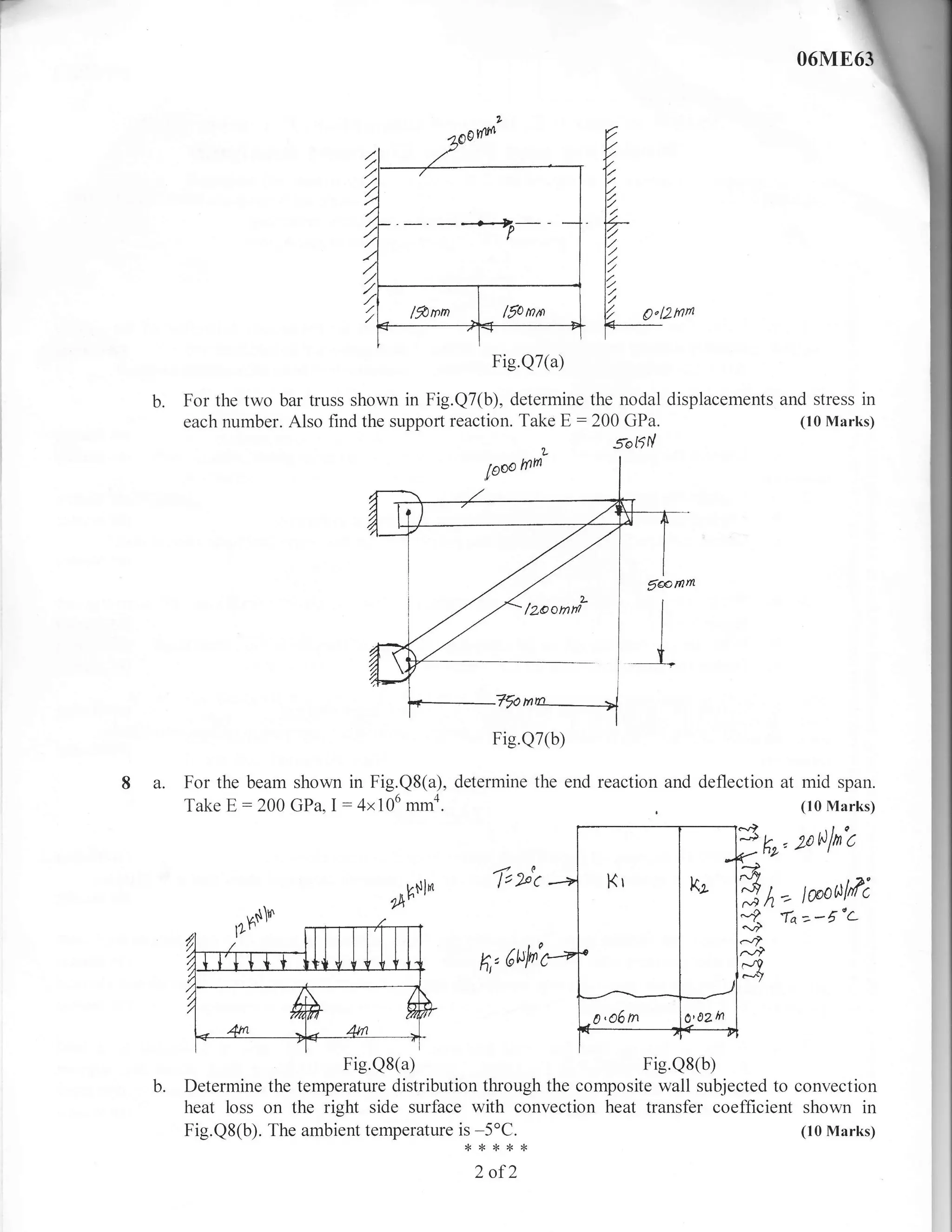
Z 7 a. A bar is having uniform cross sectional area of 300 mm2 and is subjected to a load
6 P : 600kN as shown in Fig.Q7(a). Determine the displacement field, stress and support
o reaction in the bar. Consider two element and rise elimination method to handle boundary
conditions. Take E :200 GPa. (10 Marks)
I of 2](https://image.slidesharecdn.com/modellingandfiniteelementanalysis-130307015147-phpapp02/75/Modelling-and-finite-element-analysis-Question-Papers-1-2048.jpg)
![r-
I
I
06ME63
USN
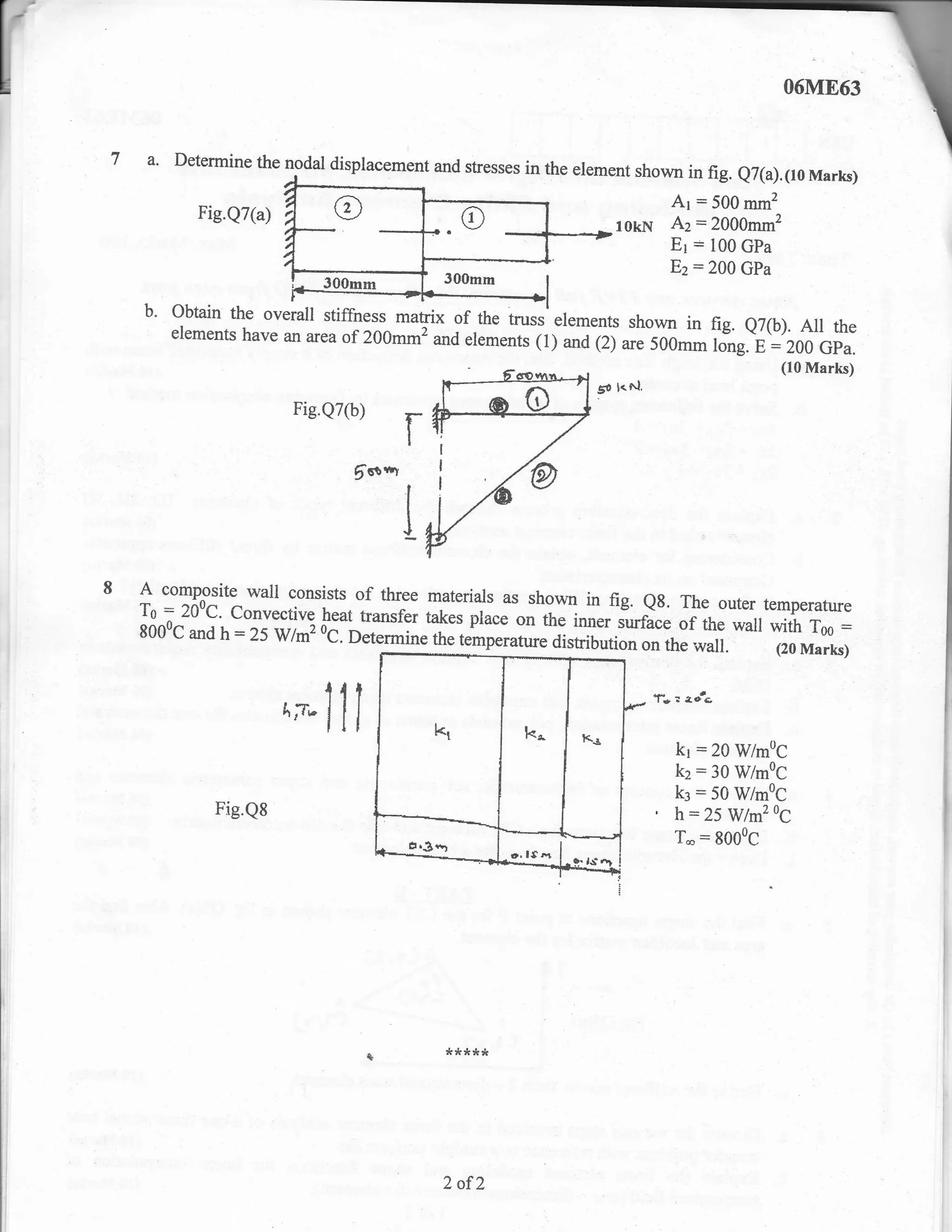
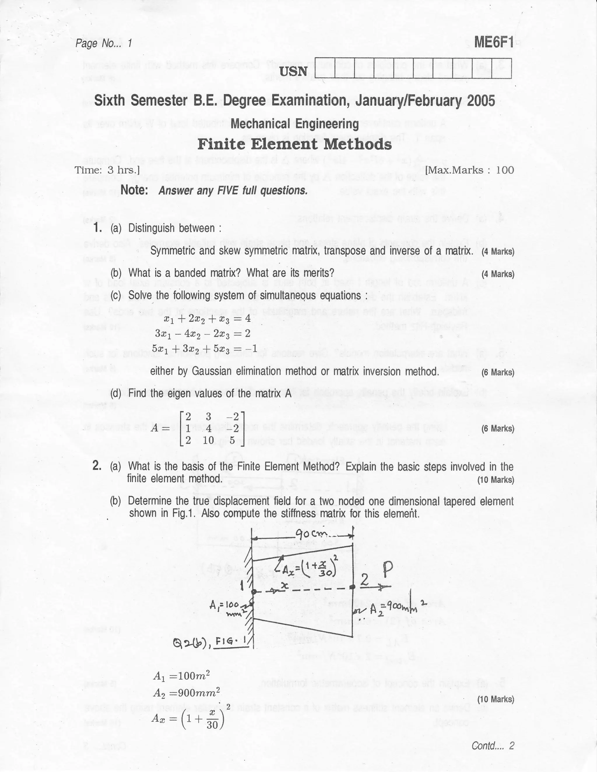
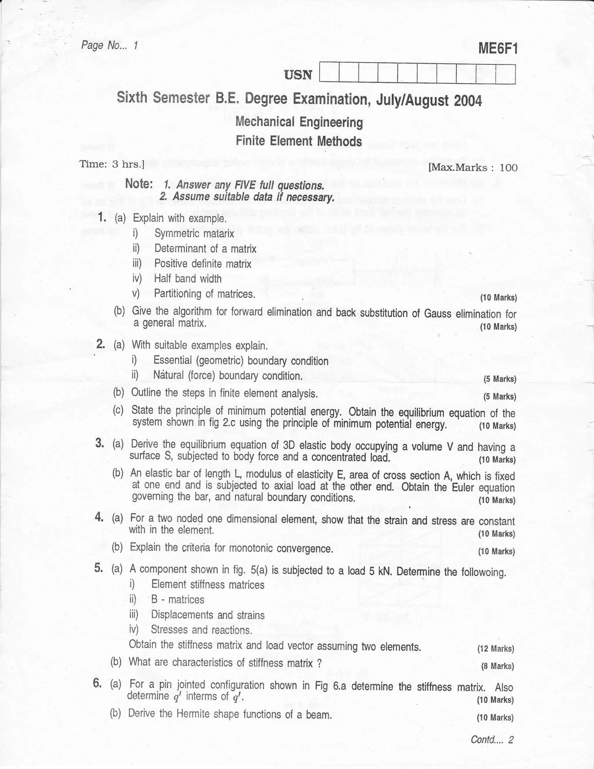
SixthSemesterB.E.DegreeExamination,December2010
Modeling and Finite Element Analysis
Max. Marks:100
Time:3 hrs. selecting
Note: Answer ony FIVE futl questions'
at least TWO questions from each part'
PART _ A
,9
o
ffi'"-" tt for two dimensions' (06 Marks)
H
I a. Explain, with a sketch, plain stress
p*"'ii"f energy' Explain the potential energy' with usual
"in
a
(g b. State the principles of minimu* (06 Marks)
notations.
c. t^hTT: the steps invotved in Ravleigh-Ritz methog?
DeTnTl:,'X ul?l]":::'*'
d
shown in Fig.l(c). use second degree
::#::
()
d
0) ffii il'r'ffi:i:.1il;J*_d#;,I;J;;g-^
approximation, for the displacement'
(08 Marks)
39 iolynomial
d9
-o ,,
ao"
Fm
.=+
'E-f
b?p
Fig.l (c).
Pfr
method with finite element methocl'
o> (04 Marks)
!1 a 2a. Bring out the four differences in continuum with example'
b. What do you underrtuod FEM?
eri"ny e*piain the steps involved in FEM'
acd
the generai node numbering *d t"l-ff:;Tl
5(J
do
Write properries of stiffness matrix K. Show - (06 Marks)
the half bandwidth-
6d
{tz Marks)
}E 3a. What is an interpolation function? ,..r - of convergence ,
-r ^^--.^- requirements'
tr5 b. what are convergence requirements? Discuss three
conditions
(08 Marks)
Write a shot notes on :
!O
oe c. -
o- gt
Eo. i1 C.o*etrical isotropy for 2D Passal triangle (CST) elernent' with a sketch' (lG Marks)
ii) Shapg function for constant strain triangrilar
si ^9
bar eiernent, in natural co-ordinates"
'@q 4a. Derive the shape functions for the one-dimensional (08 Marlcs)
quadrilateral eler'rent, in natural co-'rdinates'
Derive the shape functions for a four-node
L0
b. (08 Marks)
>.k
mo (04 Marksi
c. Write four properties of shape functions'
g0
=(6
tr> PART - B
59
o-
U<
5a. Derive the following :
1) Element stiffness matrix (K")'
il Element load vector (f)
c.i
-i
() (12 Manlis)
o Uy aire"t method for one-dimensional
bar etrement'
Z (l-1) for constant strain triangle (csr)'
b. K:ff:"Iffi::f the Jocabian transformation matrix (08 Marks)
(08
d
o
a (06 Marks)
6a.Explainwithasketch,one-dimensionalheatconduction. for heat conduction in one
b.Derivetheelementmatrices,usingGalerkinapproach, (10 Marks)
dimensional element' (04 Marks)
dimension'
c. Explain heat flux boundary condition in one](https://image.slidesharecdn.com/modellingandfiniteelementanalysis-130307015147-phpapp02/75/Modelling-and-finite-element-analysis-Question-Papers-5-2048.jpg)
![06M863
USN
May/June 20L0
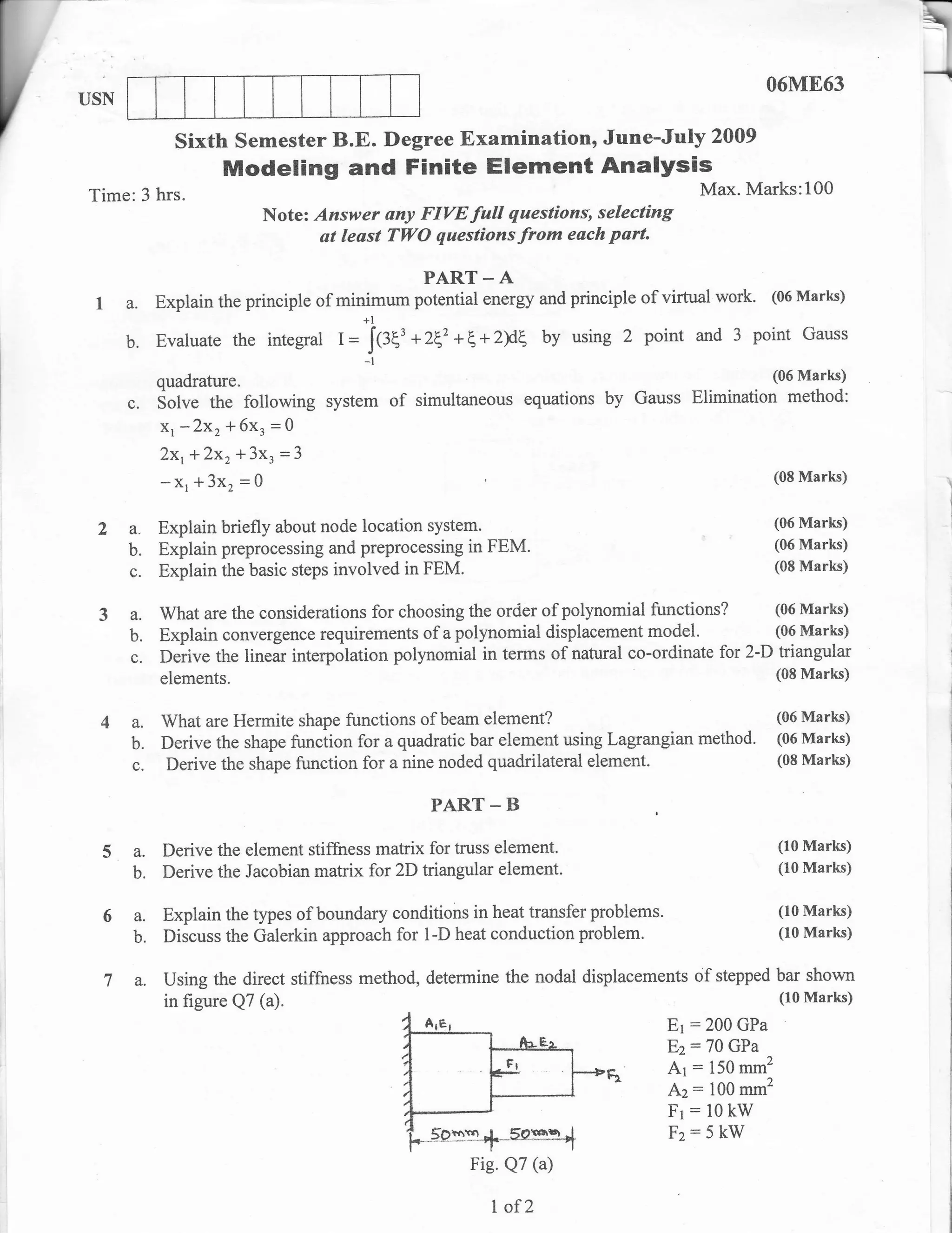
Sixth semester B.E. Degree Examination,
Modeling and Finite Element Analysis
Max' Marks:100
Time: 3 hrs.
d questions, seleeting atleast TIYO from each part'
o
o
Note: Answer any FIVE futl
a PART - A
of a simply supported beam with
(g
i
! a. Using Rayleigh Ritz method, find tt. ,il*l*--a"flection (10 Marks)
'o
() point load at center' . . -- ,--- ^^-.^+r^-- L., I],,,oci;rn eli method'
by Gaussian elimination
b. Solve the following system of simultaneous equations
(B
o
B9
qp- 4xr f 2W+ 3x3:4
2xr * 3x2* 5x3:2 (10 Marks)
'=h
Zxr * 7xz: 4
aoll
t-6
.= e'l 2a.Explainthedescretizationprocess'sketchthedifferenttypesofelementslD'2D'3D
(06 M'::Y)
cdS
c^ bI)
!i {) elements used in the finite element
analysis' -..,-- L-- A:-^
!'a
otr
rA b. considerinil;gton"rrt,.ou.oio it. "tl*.rrt
stiffness matrix by direct stiffiress
fir;111*;
eE
Comment on its characteristics' tudti9,}*rr.ut
o7 the properties that the shape flrnction should
8z a. De{ine
"
J# #ffi;. irh;;*"
oid
?d
6o criteria with suitable examples and compatibil*
*o*T#H:i;
do 3 a. Explain the convergence
boc
.dd
b.
FEM.
Explain simplex, complex and multiplex
elements using element shapes' (06 Marks)
rk coordinates for one dimensionai
}E
!o= c. Explain linear interpolatiorr, potyrro*ials
in terms
"igilu"r - (06 Marks)
!rg
-2" ts
simPlex element'
irO
oe
E3 ."t,,rte'Pr vr revr*r*.
4a,Explaintheconceptofisoparametric,subparametricandsuperparametricelementsanrj
(06Marks)
o9'
tro theirurrr'to a ,1 r:--ri^^^*a
o-i
b.DerivetheshapefunctionsforaCsTelementandalsothedisplacementmatrix.(08Marks)
for abeam element'
(06 Marks)
9E
A,E
c. Derive the Hermite shape nn.ti*
=9
LO PART. B
shown in fig' Qs(a)'
s a. Find the shape tunctions forpgintp ruiffi"lement
o.<
>.(I at
g";o ^t11r11r*;
(10 Marks)
6E area and Jacobian the eiement'
matrix
AE 61 8)
tr>
=6J
Ek
'P*
_h C6rsJ
o< I
..I e.i Fig.Qs(a) I
(trt{
C' C$,
o
z (10 l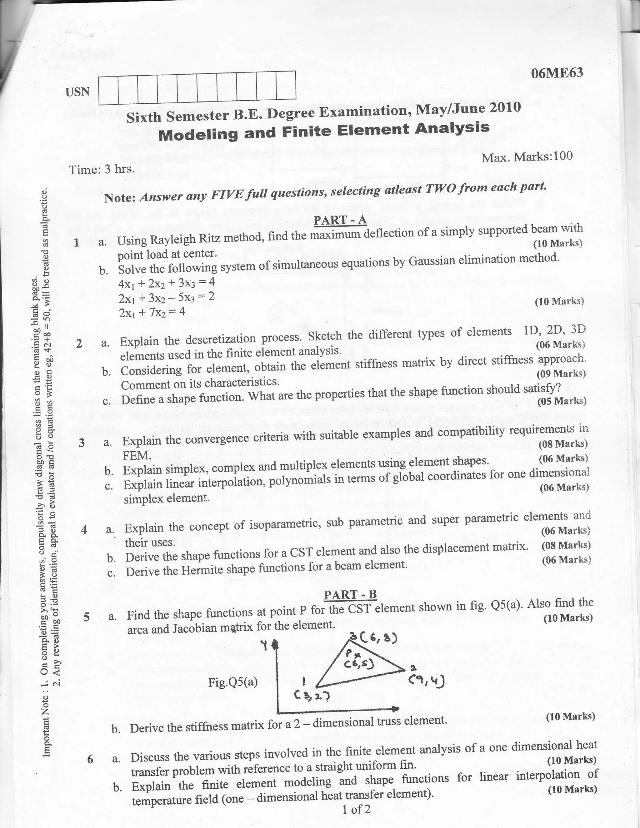
![u
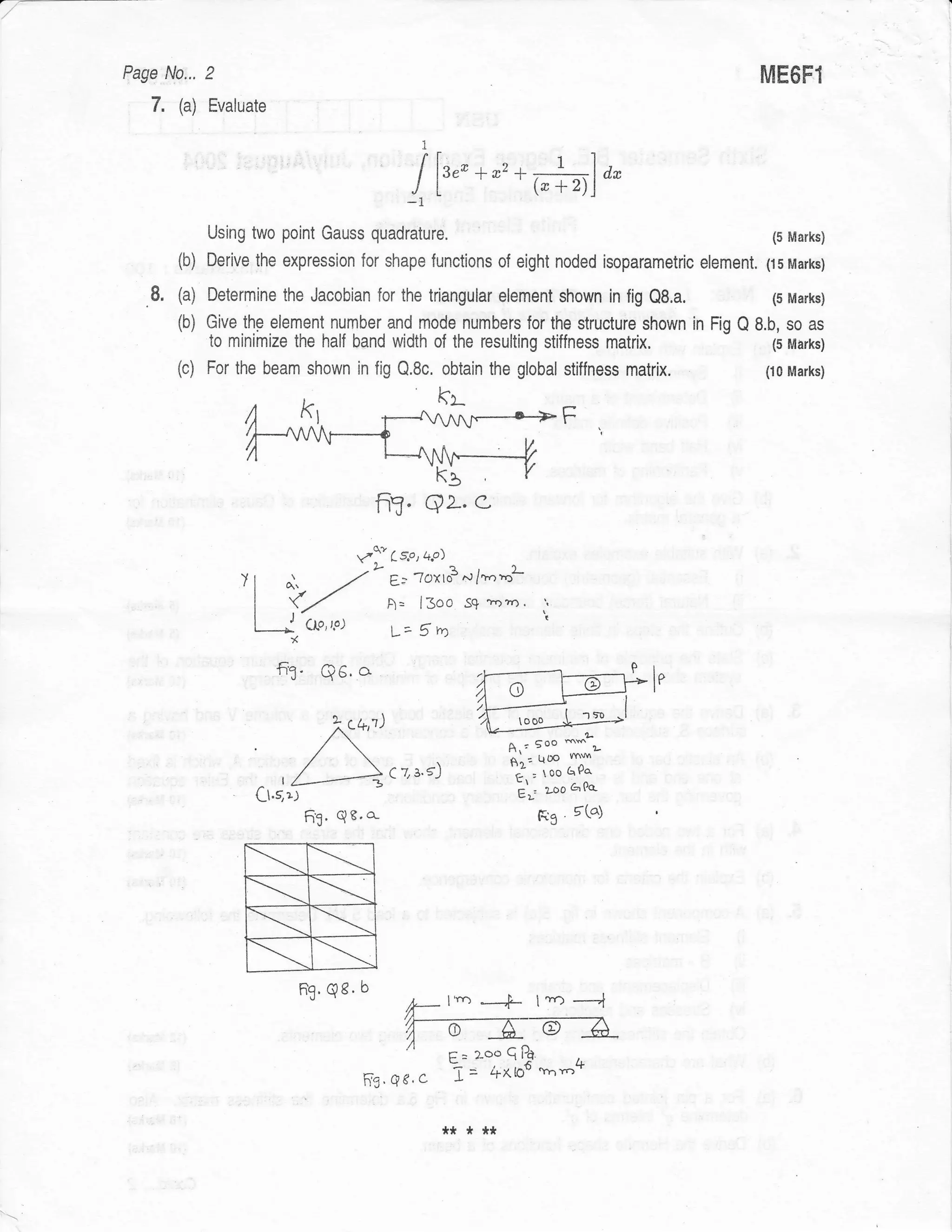
ME6Fl
-
USN
OLD SCI{EME -;?
l--/--
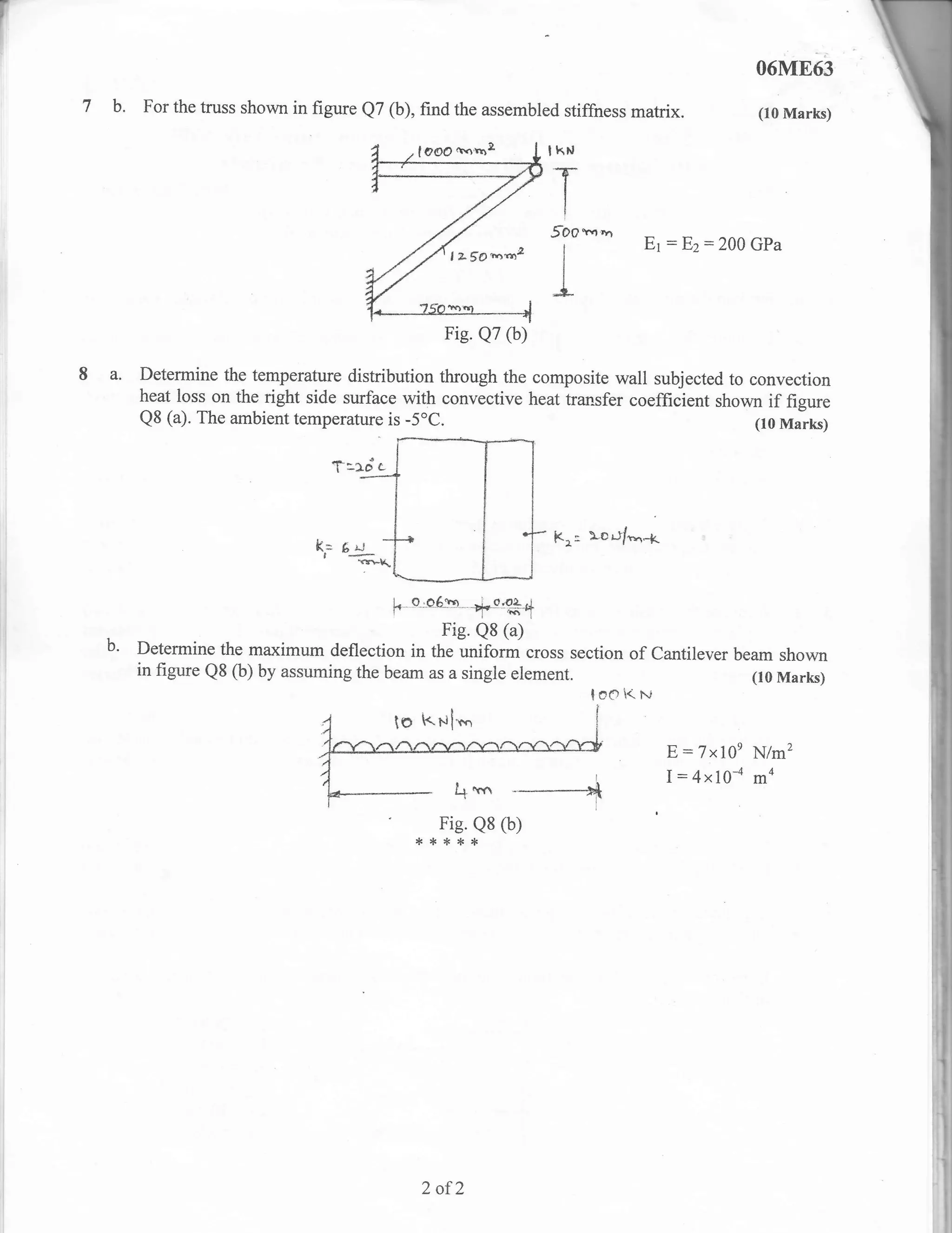
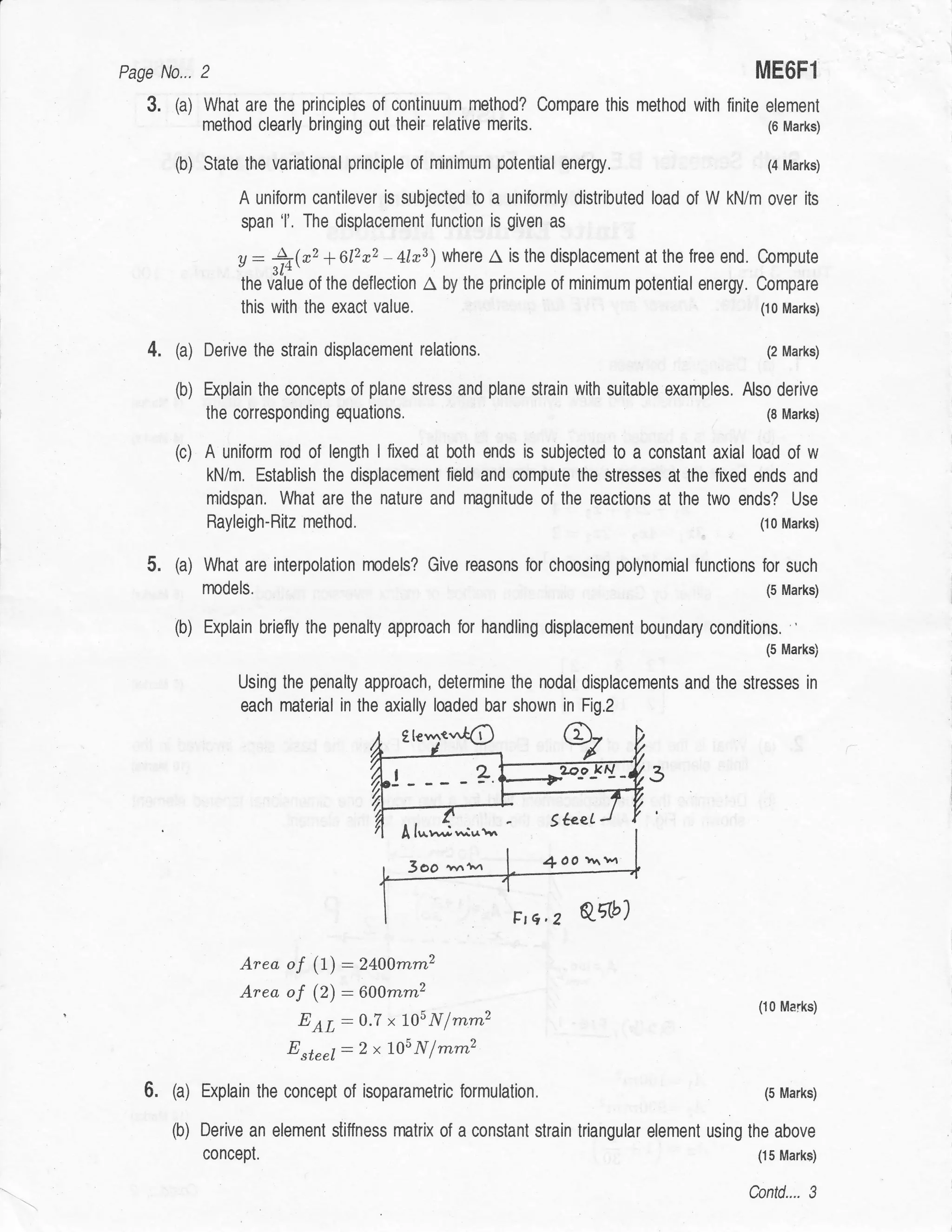
sixth semester B.E. Degree Examination, July 20A6
Mechanical Engineering
Finite Element Methods
Time:3 hrs.l [Max. Marks:100
Note: Answer any FIVE full questions'
(03 Marks)
Define functional.
(10 Marks)
Derive Euler's Langranges's equation'
(07 Marks)
Expiain principle of minimum potential energy'
Briefly explain the steps involved in FEM'
(10 Marks)
(10 Marks)
Derive shape functions for CST triangular element in local co-ordinater.
Explain Banded matrix. Write an algor'ithm for Guass elimination technique'
(10 Marks)
Explain Raieigh's Ritz method in detail' (10 Marks)
4 What do you understand by weak form of differential equation. (05 Marks)
a*,..'u_-,
. 3j!.j
ft, ="lS$*
tY,,Y.'d.,c
:1
u
'.j
'-"F,
'-lt
ffi':gnr*:.et*r-** bar whose cross
i) For the above problem compute [B] and [c] matrix. It is^tapered
- section area decreases linearly from t-000 m*2 to 500 Take E:2x 10s N/mm2'
mm2.
ii) Use two elements and findthe nodal displacements. (15 Marks)
a. Derive shape functions and stiffness matrix for beam element' (15 Marks)
b. Explain the need of Jacobian transformation matrix. (05 Marks)
a. Explain in detail ISO - parametric, sub - parametric and Super - parametric
(10 Marks)
elements.
b. Explain "penalty approach" for handling the boundary conditions' (10 Marks)
a. Discuss the requirements to be fulfilled for the convergence of FEM solution' Marks)
(10
b. Derive FEM equation by variational principle' (10 Marks)
Write short notes on anY four :
a. Pascal's triangle d. Truss element
b. Local - co - ordinate sYstem e. Shell element
c. Patch test. f. EliminationaPProach'
:t:t:k* *](https://image.slidesharecdn.com/modellingandfiniteelementanalysis-130307015147-phpapp02/75/Modelling-and-finite-element-analysis-Question-Papers-11-2048.jpg)
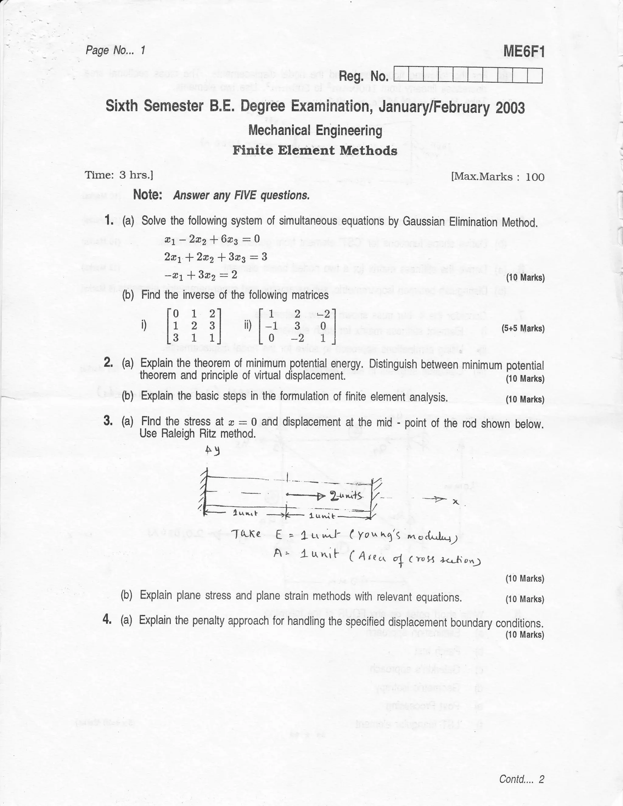
![Poge No,,. I ME6FI
Reg. No.
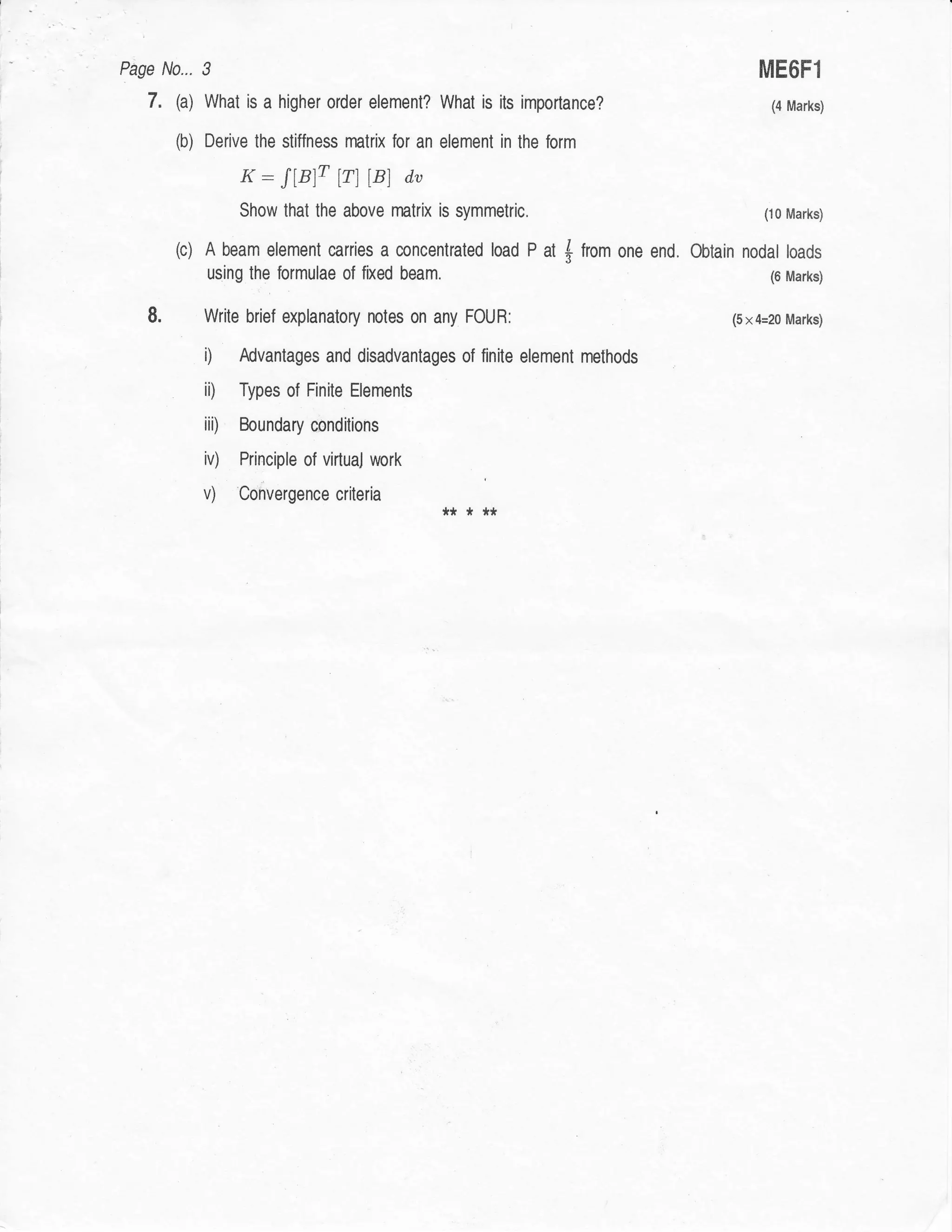
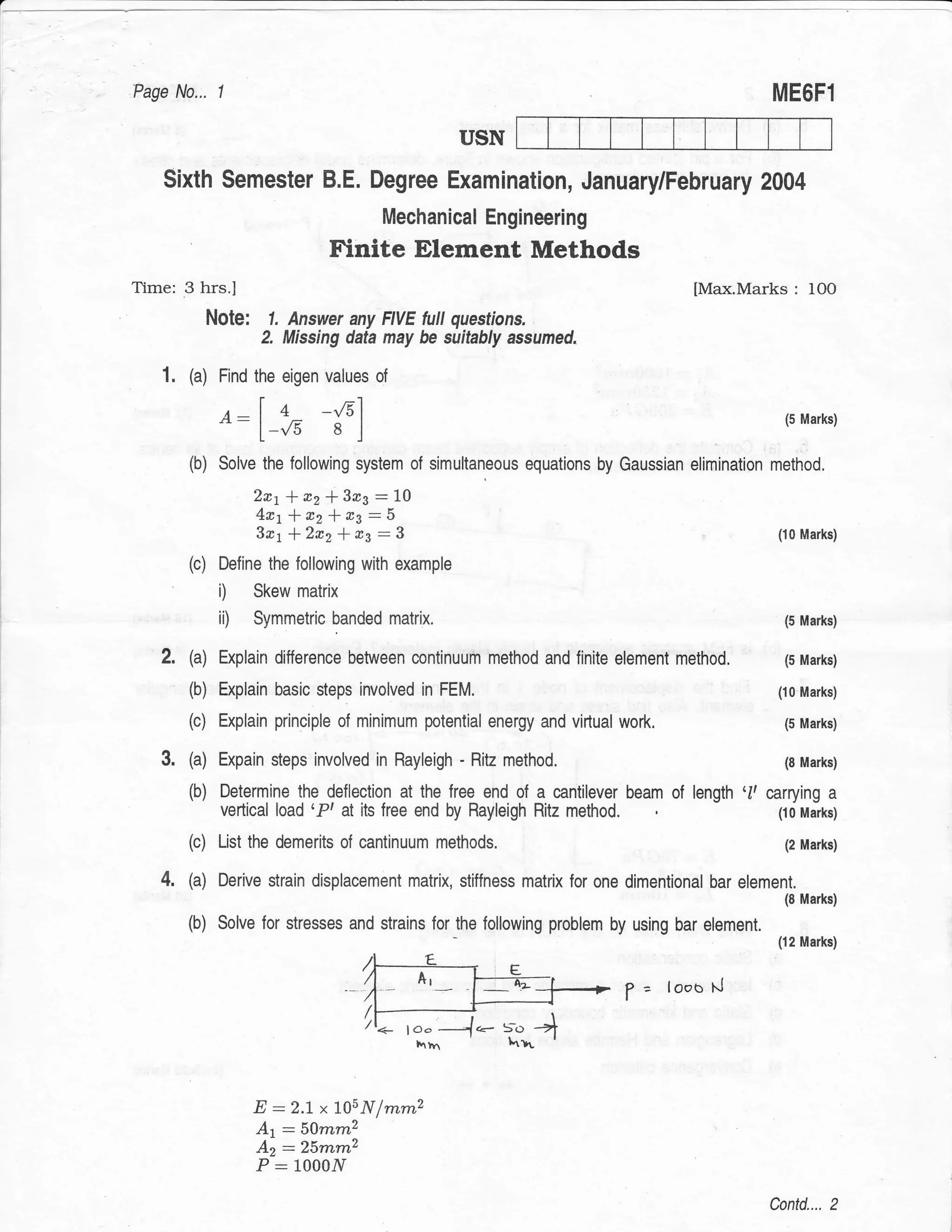
Sixth Semesler B.E. Degree Exominolion, Jonuory/Februory 2006
Mechonicol Engineering
(Old Scheme)
Finite Elemenl Methods
Time: 3 hrs.) (Mox.Morks: 100
NOtg: Answer any FVE lull questions.
l. (o) Find the inverse of
[lt] (5 Morks)
ror a:
[3 ]]
,:l; {l
Find : i) AB ii1 gT 4T (5 Morks)
Solve by Gouss eliminotion
2q * * rJ: -7
3x'2
5r1 * n2 * a3: Q (10 Morks)
321 *2x214x3:11
2. @t Whot is finite element method? Whot ore the odvontoges of FEM over finite
difference method? (4 Morks)
(b) Exploin boundory volue ond initiol volue problems using suitoble exomples.
' (8 Morks)
(c) Exploin the steps involved in the finite element onolysis of solids ond structures.
(8 Morks)
.
3. (o) whot is meont by 'Bclnd width' of o motrix? Give on exomple. Exploin why it
should be minimized. (6 Morks)
(b) Stote the principle of minimum potentiol energy, ond derive on expression for totol
potentiol energy of o solid bor under compression. (6 Morks)
(c) Exploin the Royleigh-Rit method with on exomple, (8 Morks)
4. (o) Exploin the Golerkin's opprooch for obtoining stiffness motrix of o bor element,
(10 Morks)
(b) TwopointsPl(10,5)ondP2(80,10)onosolidbodydisplocesto PlOO.z,b.4)ond
P;(80.5,10.2) ofter looding. Determine normol ond sheor stroins. (10 Morks)
Confd.,.. 2](https://image.slidesharecdn.com/modellingandfiniteelementanalysis-130307015147-phpapp02/75/Modelling-and-finite-element-analysis-Question-Papers-12-2048.jpg)
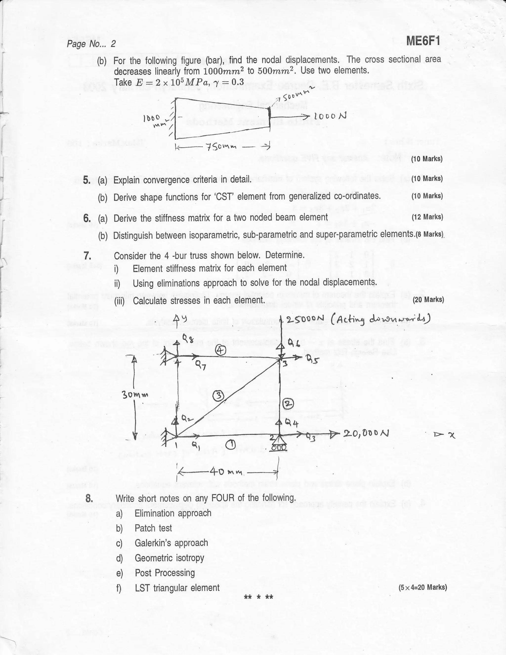
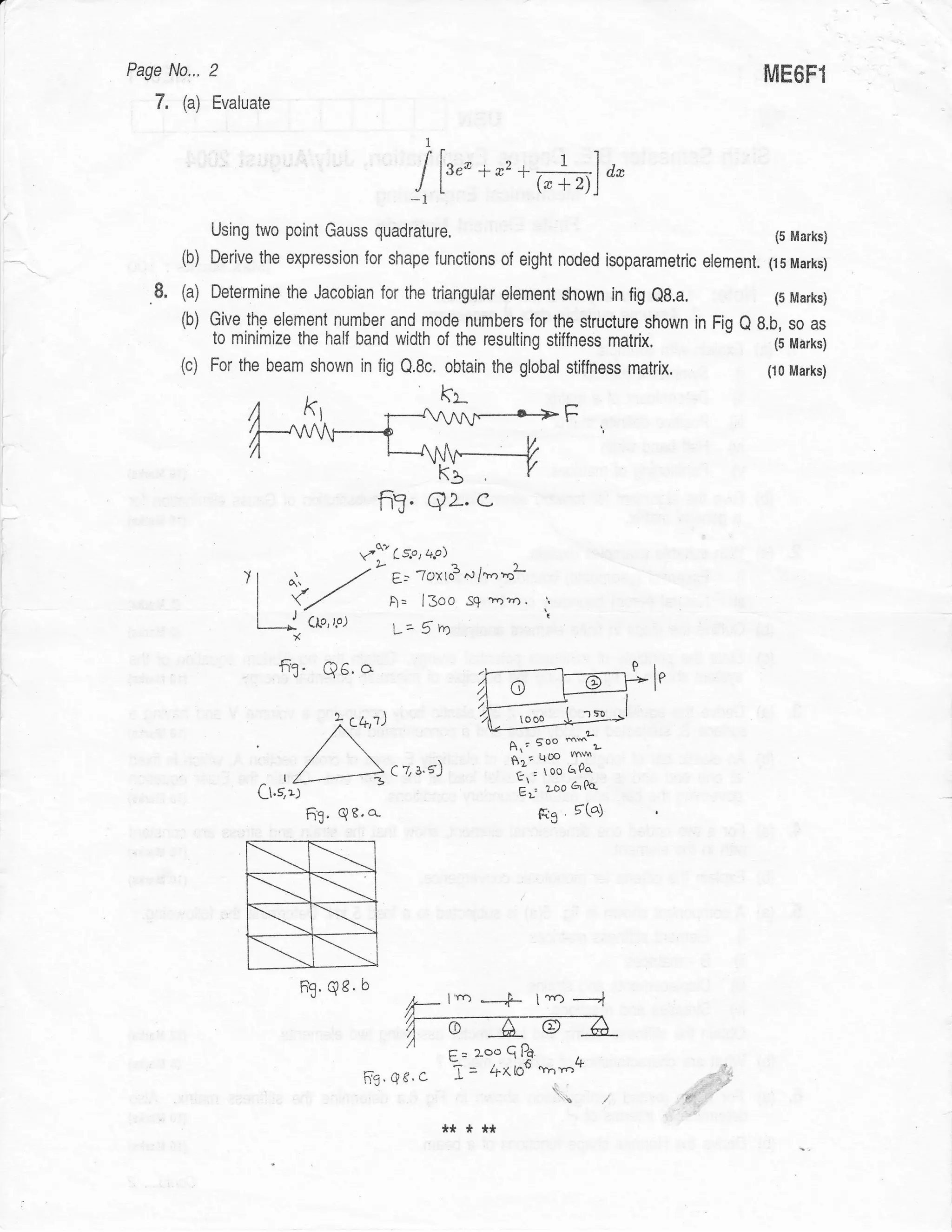
![Poge No,,, 2 ME6FI
5. A solid stepped bor os shown in fig.l is subjected to on oxiol force. Determine the
following
D Element ond ossembled stiffness motrix
iD Displocement of eoch node
iii) Reoction force ot fixed end (20 Morks)
2-
A,=t0O mm.
*r=1-Oo mm' Lku
E = 200G Pa
I t'r= ro Q Po
6. (o) Whot is Jocobion Motrix? Derive o Jocobion motrix for Two-Dimensionol element.
(10 Morks)
,, l]
(b) Derive shope function CST triongulor element. (10 Morks)
7. @) Derive shope functions for o l-D quodrotic element with 3 nodes. (10 Mofts)
. (b) Exploin convergence criterio ond potch test in brief, (10 Morks)
8. Write short note on ony FOUR:
o) Voriotionol opprooch
'b) Hermition shope functions
c) Penolty opprooch for hondling boundory conditions
d) Logronge ond serendipity fomily of elements
e) ISO porometric: elements (5x4 Morks)](https://image.slidesharecdn.com/modellingandfiniteelementanalysis-130307015147-phpapp02/75/Modelling-and-finite-element-analysis-Question-Papers-13-2048.jpg)
![Page N0... 2 ME6Fi
5. (a) For the one dimensional truss element, develop the element stiffness matrix in the global
coordinate system. (10 Marks)
(b) Determine the nodal displacement and stress by using truss element. (10 Marks)
(a) Derive the stiffness matrix for a two node beam element. (10 Marks)
(b) For the beam shown in fig,Q.No.6(b). Determine the maximum deflectlon and the reaction
at the support. El is constant throughout the beam. (10 Marks)
7. (a) What is the significance of the band width? lllustrate best method of node numbering with
an example. (5 Marks)
(b) Evaluate the following by Gaussian quadrature
i) /: /]i (s"* + *, + #)da by one point and two point formula. (3 Marks)
ii) I : I: * OV 3-point formula. (8 Marks)
8. Write short nole on the following :
(a) Coordinate systems
(b) Convergence criteria
(c) Variational method
(d) Plane stress and plane strain conditions
(e) Penalty approach for handling boundary conditions. (5x4=20 Marks)
*****](https://image.slidesharecdn.com/modellingandfiniteelementanalysis-130307015147-phpapp02/75/Modelling-and-finite-element-analysis-Question-Papers-15-2048.jpg)
![a
Poge No.,. I ME6FI
Reg. No.
Sixth Semesler B.E. Degree Exominolion, Jonuory/Februory 2006
Mechonicol Engineeilng
(Old Scheme)
Finiie Elemenl Methods
'1.
Time: 3 hrs.) ':.
(Mox.Morks: 100
NOle: Answer ony FIVE tuil queslions.
I. (o) Find the inverse of
[r ol
lo rl (5 Morks)
,o, a:
[3 1] ,:l; {l
Find : i) AB ii1 BT ar (5 Morks)
(c) Solve by Gouss eliminotion
2*t+3a2*nJ:-1
541*e2*rs:0 (10 Morks)
3rr + 2a2l4a3 -']".1
2. @, Whot is finite element method? Whot ore the odvontoges of FEM over finite
difference method? (4 Morks)
(b) Exploin boundory volue ond initiol volue problems using suitoble exomples.
' (8 Morks)
(c) Exploin the steps involved in the finite element onolysis of solids ond structures.
(S Morks)
: .
3. tol whot is meont by 'Bcind width' of o motrix? Give on exomple, Exploin why it
should be minimized, (6 Morks)
(b) Stote the principle of minimum potentiol energy, ond derive on expression for totol
potentiol energy of o solid bor under compression. (6 Morks)
(c) Exploin the Royleigh-Ritz method with on exompte. (8 Morks)
4. (o) Exploin the Golerkin's opprooch for obtoining stiffness motrix of o bor element,
(10 Morks)
(b) TwopointsPl(10,8)ondP2(80,10)onosotidbodydisptocesto pl(Lo.z,b.4)ond
Pj(80.5,10.2) ofter looding. Determine normol ond sheor stroins, (t0 Mql1s)
Confd.... 2](https://image.slidesharecdn.com/modellingandfiniteelementanalysis-130307015147-phpapp02/75/Modelling-and-finite-element-analysis-Question-Papers-23-2048.jpg)
![a
-----
'
-'-t/'
Page N0,,. I ME6F1
USN
Sixth Semester B.E. Degree Examination, July/August 2000
Mechanical Engineering
Finite Element Methods
Time: 3 hrs.I [Max.Marks : 10O
Note: Answer any FIVE futt questions.
1. (a) Given o:l; i], ort.,*in.
i) Inverse of matrix ii) Eigen values. (10 Marks)
(b) lf ,7"r: [€, 1-(2], evaluate /, wT Nag (5 Marks)
(c) Explain symmetric banded matrix. (5 Marks)
2. (a) With an example explain Rayleigh -Ritz method. (10 Marks)
(b) State the principle of minimum potential energy. (4 Marks)
(c) Sketch the quadratic and Hermite shape functions. (6 Marks)
3. (a) Derive the following characteristics of three noded l-D element.
i) Strain displacement matrix [B]
ii) Stiffness matrix [frr] (10 Marks)
(b) Solve for nodal displacements and stresses for the structure shown in fig 1. Use penality
approach to apply boundary csnditions. (10 Marks)
h t"laao n{' 2"17o frrn*
.,€ r 2lo$ pa
*1,€=zo$fo"
?JaoN
4. (a) Derive an expression for
i) Jacobian matrix
ii) Stiffness matrix for axisymmetric element. (10 Marks)
Contd.... 2](https://image.slidesharecdn.com/modellingandfiniteelementanalysis-130307015147-phpapp02/75/Modelling-and-finite-element-analysis-Question-Papers-29-2048.jpg)
![_ _
, ___:_
Page N0... 2 ME6F1
(b) 0onsider a rectangular element as shown in Fig.2. Evaluate J and B matrices at
(=0, =0, (10 Markr)
+
+
C1i,o,{)
cv>-
t A,>
L -t a)
(0, ,)
5. (a) Explain with neat sketches the library of elements used in FEM. (10 Marks)
(b) Using Gaussian quadrature, evaluate the following integral by two point formula
d, /], (€2 + zrt€ + rf) dt drt (10 Marks)
6, (a) For the pin jointed_ configuration shown in Fig.3 determine the stiflness values of
'' kn, l*e and,-k2, of global stiffness matrix. (10 Marks)
O hra'tgroivl"nL'
/L
L
I
I
"l/
b MvY'
vjup ln7
>}lac?", ,
E-
(b) Derive an expression lor stiffness matrix ol a two noded beam element. (10 Marks)
7. (a) Explain in detail the leatures of any one commercial FEA software package. (l0Marks)
(b) Bring out the differences between continuum methods and FEM. (10 Marks)
Write short notes on any FOUR :
a) State functions
b) Galerkin methods
c) Elimination method of handling boundary conditions.
d) Temperature effects
e) Convergence criteria. ** * **
(4x5=20 Marks)](https://image.slidesharecdn.com/modellingandfiniteelementanalysis-130307015147-phpapp02/75/Modelling-and-finite-element-analysis-Question-Papers-30-2048.jpg)
![Page No... 2 ME6F.1
(b) Determine the nodal displacements, element stresses, and suPport reactions of
'-' thtrnuliy loaded bar ai shown in fig3"^Usi elimination method for handling
:
the bound.ry;;;;itio.o. rrr." E :"200Gpa aad load P 300&N. .
lro m lrlm,/,
Fir"3 (15 Marks)
(5 Marks)
5. (a) state tJre assumptions made in the analysis of trusses.
and
(b) For the three-bar t1ass shown in fig.4, determine the nodal {i9pl1rments
ror tmss {i9pl15n
tfre stre"s in each member. Take Inodulus of elasticity as 2OO GPa'
lTo ?< rl
1tOoo mm
I" Ff a.4
(15 Marks)
6. A beam of length 1O m, fixed at one end and suppott""{,!V l:]b:-:t
l l*-"^t*I
B;r taking,the
end carries a 2o kN;;;;A&"lia toao at the ceirier of thti spgn'
modulus of elasticity *rtoirtas 2OO GPa and moment of inertia of section
"T
as 24 x 10-6m4, determine
1. Deflection under the load, and (2O Marks)
2, Shear force and bending moment on each element'
7. (a) Derive strain- displacement relation of a cST element.
(1O Marks)
(b) For a linear quadrilateral element, derive an expression for Jacobian matrix'
8. Write short notes on arly four of the following'
i) VariationalPrinciPles.
ii) Co-ordinatesYstem.
iii) Convergence
iv) Penalty approach for handling the boundary conditions.
Quadratic shaPe t r",tot*
(4X 5=2O Marks)
v) * **](https://image.slidesharecdn.com/modellingandfiniteelementanalysis-130307015147-phpapp02/75/Modelling-and-finite-element-analysis-Question-Papers-32-2048.jpg)
![. ( c'!-t
I
*q,f
r
.;
,.1 SF --^ fi,lE6F1
Pag* fi,o... , {//
Reg, No.
Sixth $emester B.E" Degree Examlnation, Juffiugu$t 2002
Mechanical Enginering
Finite Element llethods
Time: 3 hrs.I IMax.Marks: lOO
Note: Answer any F|VE full guestfons,
1" ia) Solve the following system of siriultaneous equaticns by Gaussian Elimination Method.
2*t+*2*a3=l
&i -2rz * 343 - ll
2*t + 4nz * 3r3 : 19 (10 Marks)
(b) Write a briel note on frontal solution technique for handling large systems of algebraic
equations, (6 ffarks)
{c) Define the {ollowing with examples,
i) Symmetric matrix
ii) Banded Euare matrix. (4 Ma*s)
2" (a) Discuss the advantages and limitations of FEI';I over other numerical method'FDM.
i5 l,lark*)
(b) List the various applications of finite element method. (5 Marksi
(c) Explain the steps invoived in finiie element method lvith suitaCIie exampies. (10 Marksi
3" (a) Derive strain-displacement relationship for a two dimensional soiid mechanics problem.
{10 Marks}
(b) Explain plane siress and plane strain problems as applied to solid mechanics problem
with suitable examples. , , i10 Marks)
4. iai ExBlain the theorcm of mjnimum potential enerEy ancj cietive an expression {oi totai
potentiat energy ior a sne-oimensionai bar sub,;ecteci to an axtat iorce. (i 0 f'{arhsi
(b) Using direct stif{ness method, determine the nodal displacements of the bar, as shown in
Fig.1. i10 Ma*s)
$" (a) Define shape function. What are the properties that a shape funciion shoulcl satisfy?
{10 Marks}
ib) Expiain wiih suiiable examples ihe iagrange and serenciipity famiiy o{ eiements. (10 Marks}
6. (a) Distinguish between consisient and lumped load vectors through examples. (5 Marks)
(b) A stepped bar is shown in Fig.2 Calculate Jacobian J for eaeh element. Cbiain the
etemrjrit stiffness matrices and solve {or the nodal displacements by using elirnination
approach for handling the boundary conditions. {15 Mtrks}
[Use one Gauss point for Numerical integration]
Contd.... 2](https://image.slidesharecdn.com/modellingandfiniteelementanalysis-130307015147-phpapp02/75/Modelling-and-finite-element-analysis-Question-Papers-33-2048.jpg)
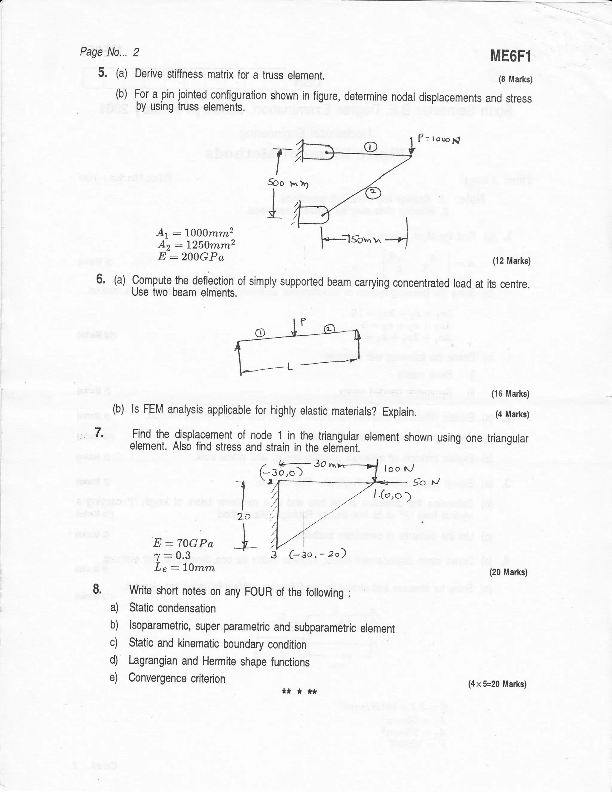
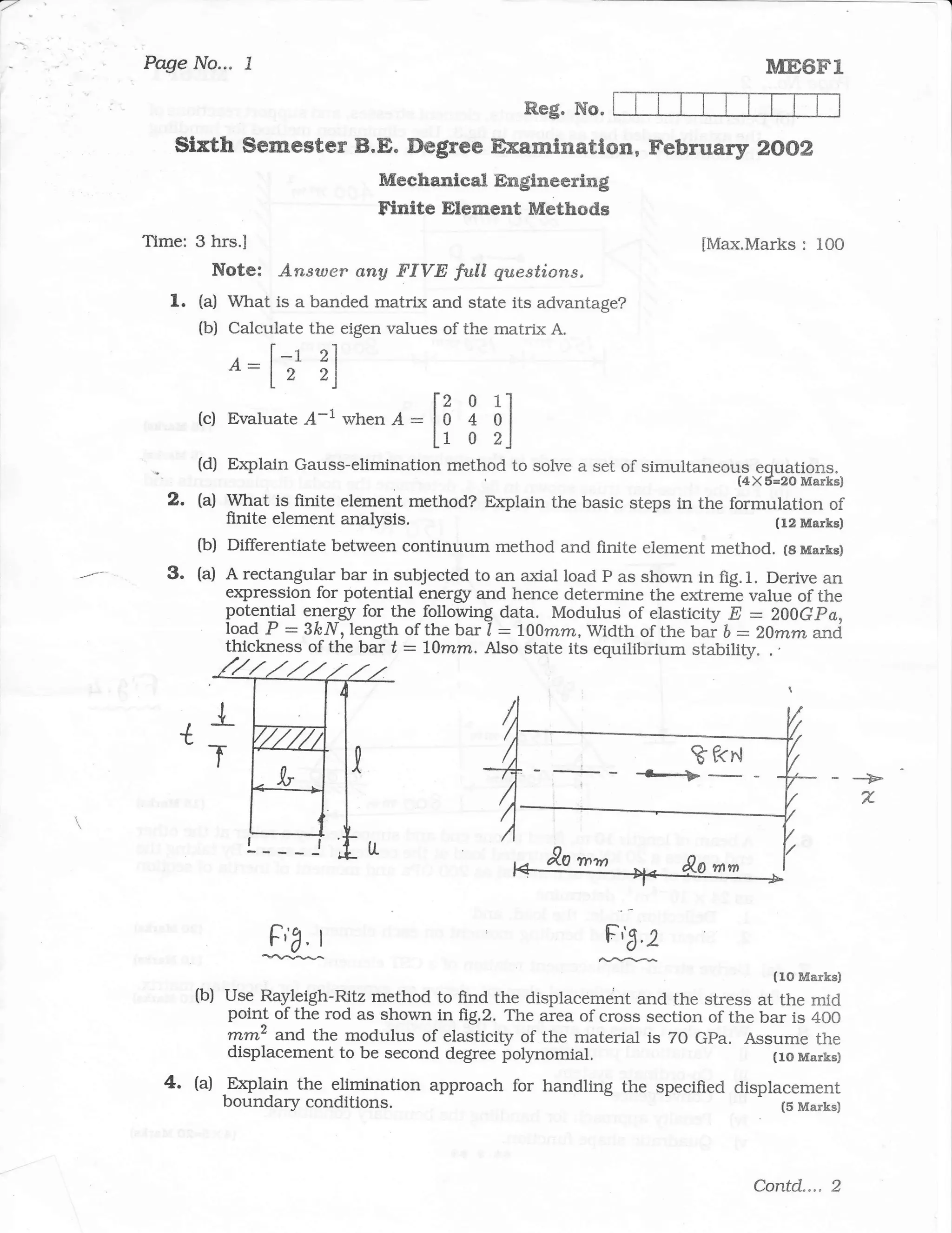
The document contains a sixth semester examination question paper for the subject Modeling and Finite Element Analysis. It has two parts with a total of 8 questions. Some of the key questions asked are: 1) Derive an expression for maximum deflection of a simply supported beam with a point load at the center using Rayleigh-Ritz method and trigonometric functions. 2) Explain the basic steps involved in the finite element method. 3) Define a shape function and discuss the properties that shape functions should satisfy. 4) Derive the stiffness matrix for a 2D truss element and the strain-displacement matrix for a 1D linear element. 5) Discuss the various
Introduction to FEM principles, including discretization, shape functions, and convergence requirements.
Derivations of stiffness matrix, stiffness vector, and Jacobian matrix for various elements, including truss and beam.
Solving structural problems using FEM, including nodal displacements, stress analysis, and methods like Galerkin and Rayleigh-Ritz.
Finite element methods applied in heat transfer problems, including deriving temperature distribution in composite materials.
Handling boundary conditions, Gauss elimination techniques, and discussing boundary conditions in FEM analysis.
Exploration of higher order elements, quadratic and Hermite functions, with practical applications and examples.
Criteria for convergence in FEM, including patch tests, and discussions of the penalty approach for boundary conditions.