Downloaded 39 times
![IUSN IOMAT3T
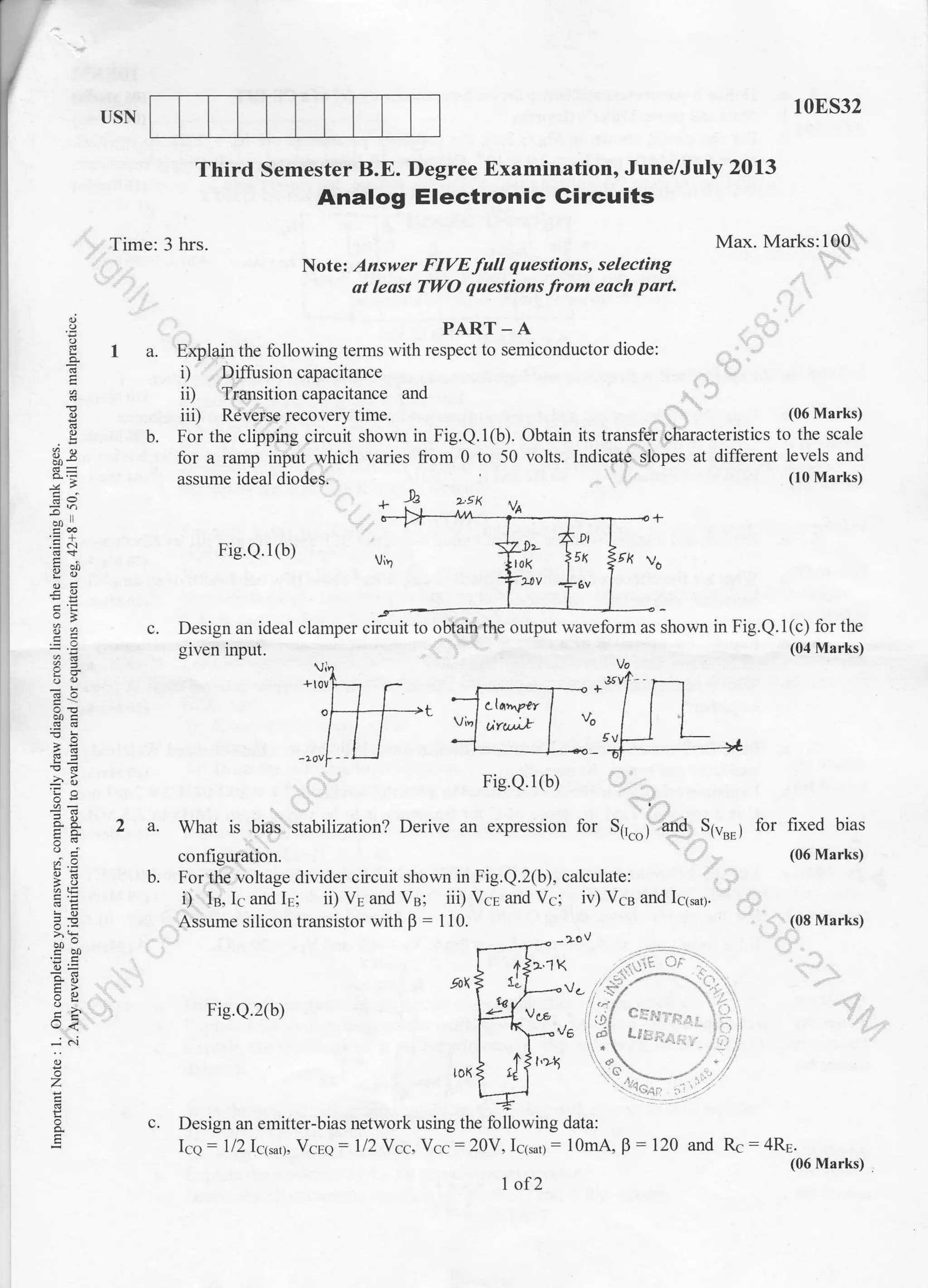
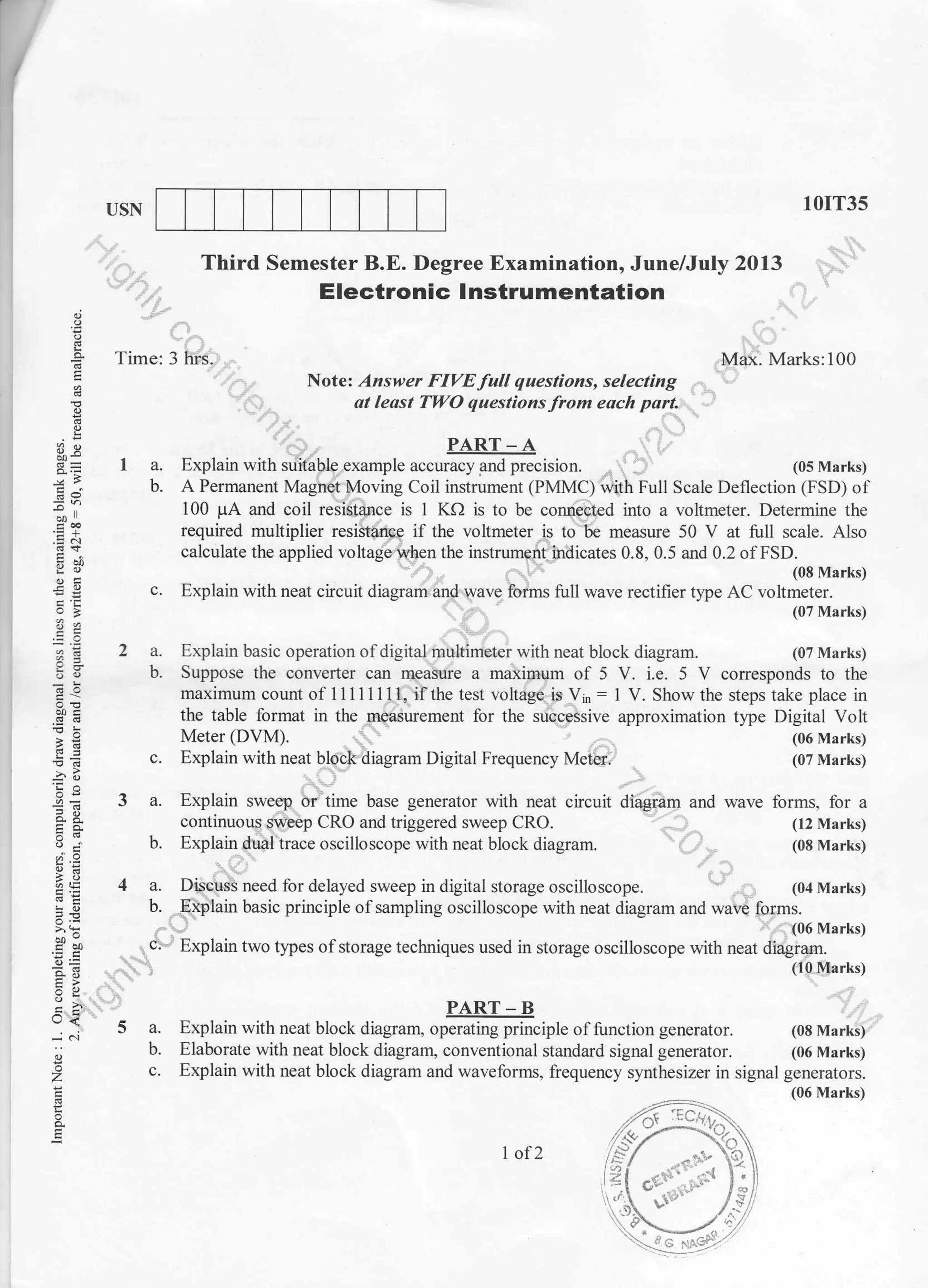
Third Semester B.E. Degree Examination, June/July 2013
Max. Marks:100
(07 Marks)
(06 Marks)
,
9
:h
96,
.g 6
-ir'E
^
!=
6d
.r=
6t=
=
-!2
;-E
3t
o<
o
z
o
at least TWO questions from each parl
PART - A
I a. Obtain the Fourier series exoansion of fr*t=l ''
if 0<xl' und hence deduce
[2r-x, if n< x<2x
-ntllIthdt
-=
-* -* ^*.""-' g l, 3, ' 52 "" "'
b. Find the halfrange Fourier sine series of it*l = {
*'
'l^
o-:*
'%
|.n-* il /,<x<t
Time: 3 hrs.
Note: Answer FIVE full questions, selecting
constant.
a. Using method of leastoI leas square. I1I a
x 2 3 4 5
v 0.5 2 4.5 8 12.5
b. Solve the following LPP graphically:
Minimize Z=20x+l6y
Subject to 3x+y>6, x+y>4, x+3y>6 andx,y>0.
c. Use simplex method to
Maximize Z: x+ (1.5)y
Subject to the constraints x + 2y 3 160, 3x + 2y < 240 and x, y > 0.
c. Obtain the constant term and coeffrcients of first cosine and sine terms in the expansion ofy
from the followins table: (07 Marks)
-.: .,: t-t/^
2 a. Find the Fourier transform of p1x;=]o
^^' ,^l
- o
and hence deduce Isrn-lcosxd*=1.
L 0. lxl>a j x' 4
(07 Marks)
b. Find the Fourier cosine and sine transform of(x): t"-a*, where a > 0. (06 Marks)
c. Fincl the inverse Fourier translorm of e-" . (07 Marks)
3 a. Obtain the various possible solutions of one dimensional heat equation u1 : c2 u** by the
method ofseparation ofvariables. (07 Marks)
b. A tightly stretched string of length ,t with fixed ends is initially in equilibrium position. It is
se1 ro vibrare by giving each point a velocity ,..4[+). Find the displacement utx. t).
c. Solveu*,,*uyy:0 givenu(x,0):0, u(x,1):0,u(1,y):0andu(0, y.):r., *n:[Hll?
fit a curve y - axb for the following data.. .
(07 Marks)
(07 Mar.ks)
x 0 600 120' 180" 240" 300 360"
v 7.9 7.2 3.6 0.5 0.9. 6.8 7.9
1of 2
(07 Mrrks)](https://image.slidesharecdn.com/3rdec-june2013-130917234554-phpapp02/75/2013-June-3rd-Semester-E-C-Question-Papers-1-2048.jpg)
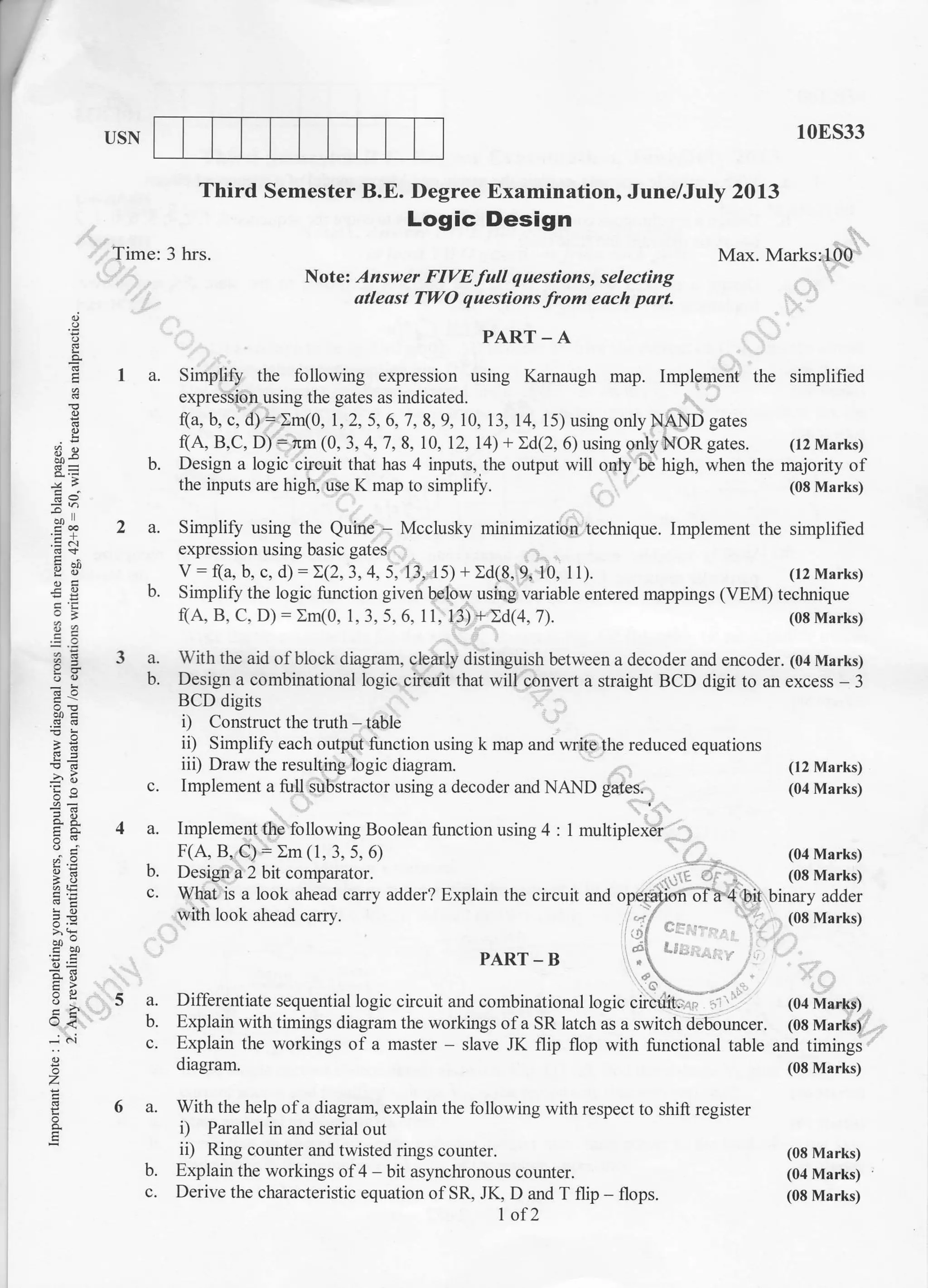
![5a.
b.
method
lrt , ,1
A=l l 3 0 l.
l, o -4]
Use f,(o) = [1, 0, 0]r as the initial eigen vector.
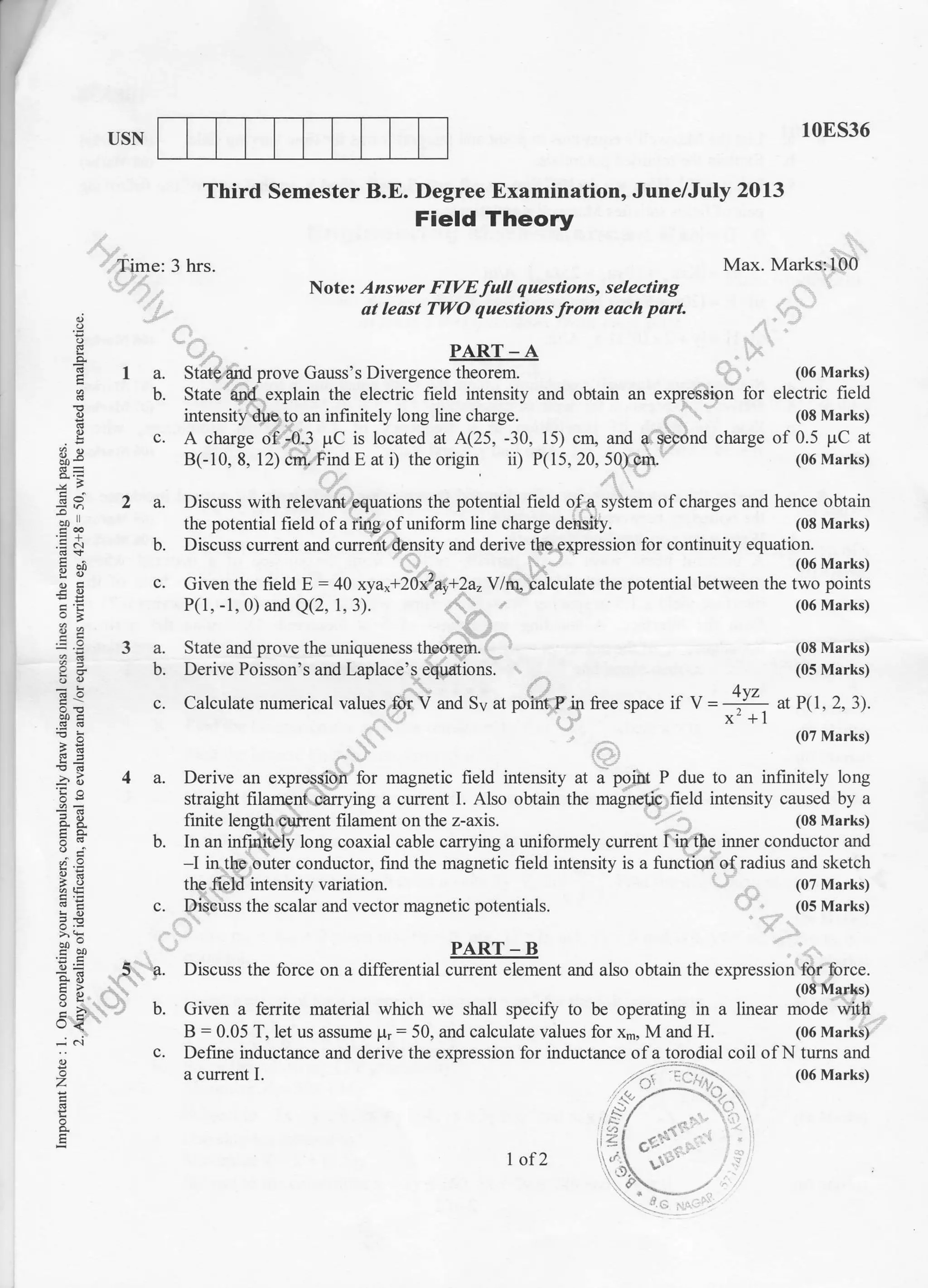
PART _ B
Using Newton-Raphson method find a real root of x * logrox :3.375 near 2.9,
3-decimal places.
Solve the following system ofequations by relaxation method:
12x+y +z=31, 2x+8y -z=24, 3x + 4y + l0z = 58
1OMAT31
corrected to
(07 Marks)
(07 Marks)
c' Find the largest eigen value and corresponding eigen vector of following matrix A by power
(06 Marks)
6 a. Inthe given table below, the values ofy are consecutive terms ofseries ofwhich 23.6 is the
fthe series.6rh
b. Construct
difference formula.
find the first and tenth terms o
x 3 4 5 6 7 8 9
v 4.8 8.4 t4.5 23.6 36.2 52.8 73.9
an interpolating polynomial for the data
(07 Marks)
given below using Newton's divided
(07 Marks)
c. Evaluate [--I "0" by Weddle's rule taking 7-ordinates and hence find log"2. (06 Marks)
jl+x'
x 2 4 5 6 8 l0
flx) l0 96 196 350 868 1746
Solve the wave equation utt ='{ux* subject to u(0, t):0; u(4, t):0; u(x,0):0;
u(x, 0) : x(4 - x) by taking h: 1, k = 0.5 upto four steps. (07 Marks)
Solve numerically the equation
# =
# subject to the conditions u(0, 0 : 0 : u(l, t), t > 0
and u(x, 0) = sin 7rx, 0 < x < 1. Carryout computations for two levels taking h : / and
(07 Marks)
for the following square mesh with boundary values
(06 Marks)
Fig.Q7(c)
la.
b.
8a.
b.
c.
Find the z-transform of: i) sinhn0; ii) coshn0.
Obtain the inverse z-transfor. of 8"
(22-1)(42-r)
Solve the following difference equation using z-transforms:
!n+zl2!n+t +yn:n with Yo:Yr =0
2 of2
(07 Marks)
(07 Marks)
(06 Marks)](https://image.slidesharecdn.com/3rdec-june2013-130917234554-phpapp02/75/2013-June-3rd-Semester-E-C-Question-Papers-2-2048.jpg)
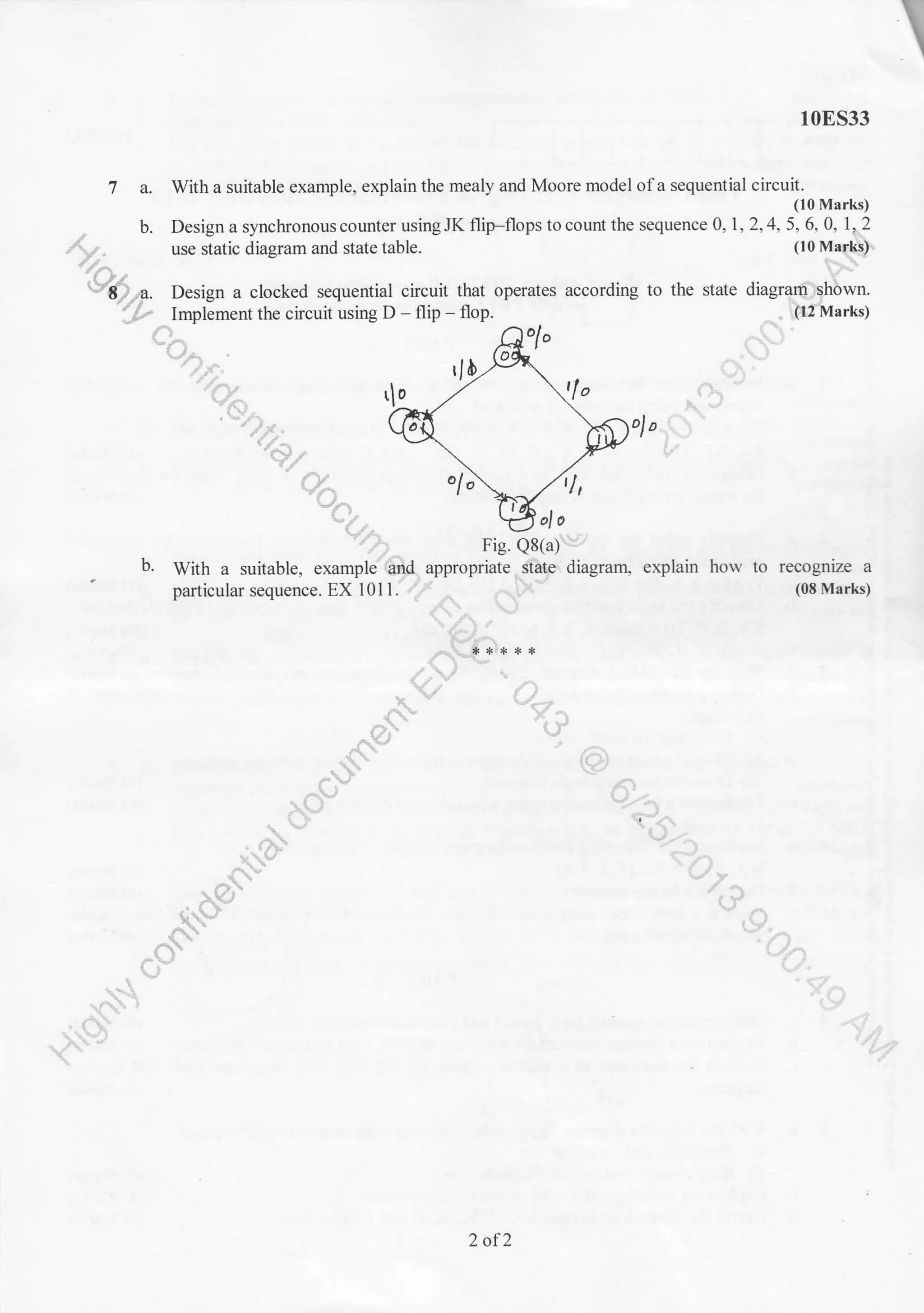
![3a.
b.
c.
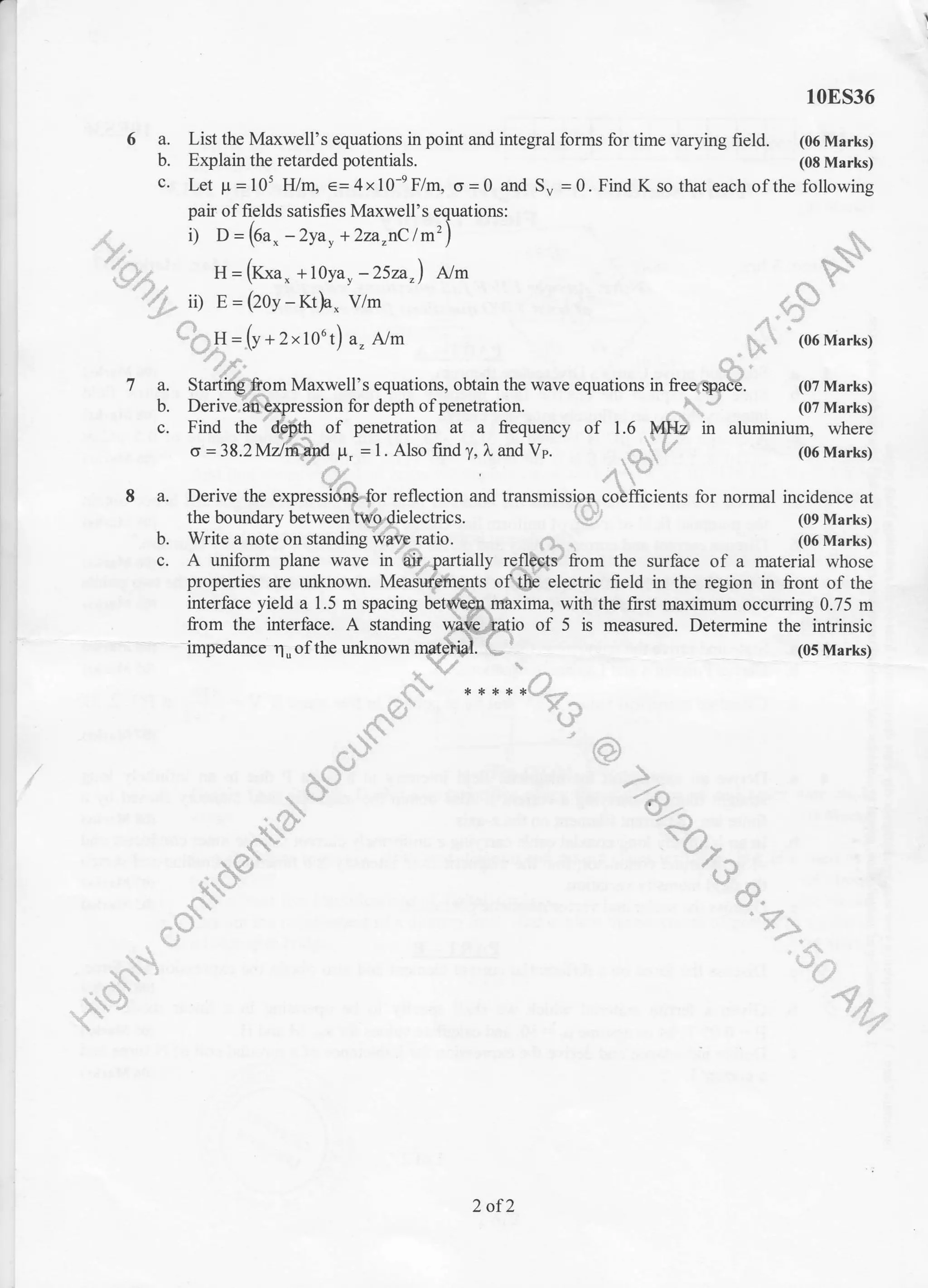
Define h-parameters and hence derive h-parameter model ofa CE-BJT.
State and prove Miller's theorem.
i) FET and BJT and ii) Enhancement and depletion MOSFET ;
10E532
(06 Marks)
(04 Marks)
(04 Marks)
(10 Marks)
i) g*; ii) ra;
(10 Marks)
For the circuit shown in Fig.Q.3(c), the transistor parameters are hib : 22{2' hn: -0.98,
h.r : 0.49 MA/V and h*:2.9 x 10{. Calculate: i) Input resistance; ii) Output resistance;
iii) Current gain; iv) Voltage gain; v) Overall voltage and current gain. (10 Marks)
c-
"L-
(L: t 1+o
Fig.Q.3(c)
Explain the low frequency and high liequency response ofa RC coupled amplifier.
(10 Marks)
Describe Miller's effect and derive an equation for Miller input and output capacitance.
(06 Marks)
Calculate the overall lower 3db and upper 3db frequency for a 3 stage amplifier having an
ll(
-1
J
4a.
b.
c.
5a.
b.
6a.
b.
la.
b.
individual frequenry fr : 40 Hz and fz:'2 MHz.
PART - B
Explain and analyze with the help of circuit a cascade BJT amplifier and list its advantages.
What are the effects olnegative feedback in arnplifier? Show how band,riatn of an(I0#iif,i]
increases with negative feedback. (10 Marks)
Explain the operation of a class B push-pull amplifier and also show that its e[ficiency is
78.50Yo and max power dissipation condition. (10 Marks)
With a neat circuit diagram, explain the operation of a transformer coupled class A power
amplifier. (10 Marks)
State Barkhausen criteria for sustained oscillations, apply this to a transistorized Weinbridge
oscillator and explain its operation. (10 Marks)
Explain workin!. of a Hartley oscillator. In a Hartley oscillator L1 = 20 MH, L2:2mH and
C is a variable. Find the range of C for liequency is to be vaiied from lMHz to 2.5 MHz.
(10 Marks)
8 a. List the difference between:
ii, JFET and MOSFET.
b. For the circuit shown in Fig.Q.8(b) V6sq: -2.5V and Ig,q:2.5 mA find:
iii) zi iv) zo and v) A,. Assume Ioss: 8rnA, Vp: -6V and Yos:20 mO.
*t9 V
>'> KiJu
HVo
l)
D
nI
ry)u
Fig.Q.8(b)
2 of 2](https://image.slidesharecdn.com/3rdec-june2013-130917234554-phpapp02/75/2013-June-3rd-Semester-E-C-Question-Papers-4-2048.jpg)
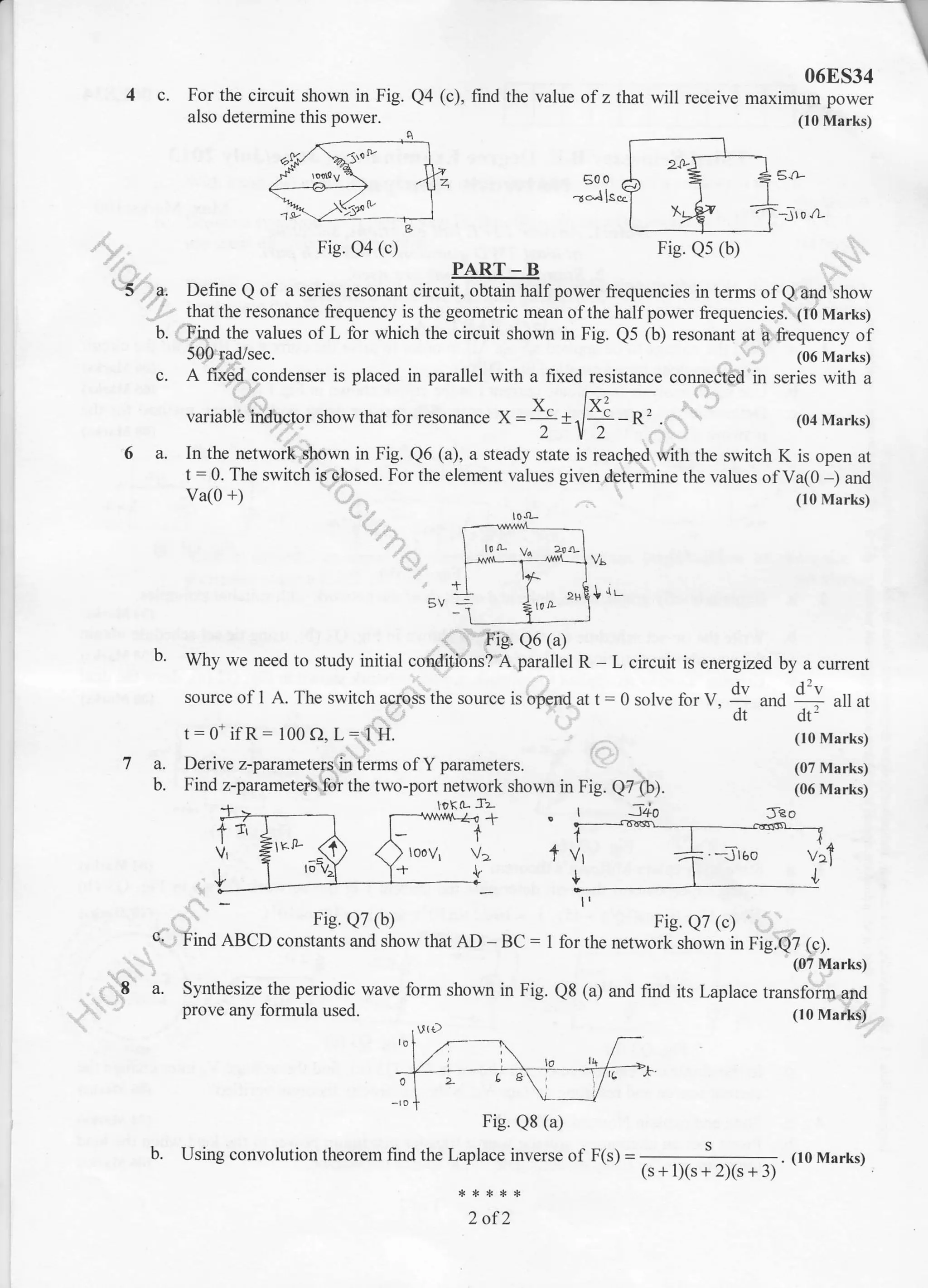
![I]SN 06E534
(08 Marks)
Q2 (c), draw the dual
(08 Marks)
L]-
(04 Marks)
in Fig. Q3 (b)
Third Semester B.E. Degree Examination, June/July 2013
Network Analysis
Time: 3 hrs. Max. Marks:100
Note:I. Answer FIVE full questions, selecting
at leosl TWO questions from each part.
2, Standard notstions are used.
3. Missing dato be suitably ossumed.
PART_A
1 a. Find the voltage to be applied across AB in order to drive the current of 10 A into the circuit
using star-delta transformation Fig. Q1 (a). (06 Marks)
b. Use mesh analysis to evaluate current I in the circuit shown in Fig.l (b). (06 Marks)
c. Determine the current and voltage across each resistor using node voltage method for the
network shown in Fig. Q1 (c). (08 Marks)I
:h
.e6
E=
=B
o. d-
9r i;
-;o
o. at
tr<
.i ..i
E
BI 2A
1rL
Fig. Ql (a)
2 a. Explain briefly graph, trees, links and cotrees of the network with suitable examples.
(04 Nlarks)
b. Write the tie-set schedule for the network shown in Fig. Q2 (b), using tie set schedule obtain
the equilibrium equations on loop current basis.
c. Explain "Duality as applied to network, for the network shown in Fig.
network.
6a
0-
E rL Fig. e2 (c)
Fie. Q2 (b)
State and explain Millman's theorem.
Using superposition theorem determine the cunent I in the network shown
given V = 10cos(105t+45), i, =16r/2r1rr105t and i, =10cos10't
3a.
b.
c.
4a.
b.
'12-
Fig. Q3 (b)f lB. vJ (u,
In the single current source cicuit shown in Fig. Q3 (c), find the voltage V* inter change the
current source and resulting voltage V*, is the reciprocity theorem verified? (06 Marks)
State and explain Nortons theorem. (04 Marks)
Prove that an alternating voltage souce transf'er maximum power to the load when the load
impedance is the complex conjugate ofthe source impedance.
Fig. Ql (c)
nig. Q1 (b)
Fie. Q2 (c)
a= 6D?0 A
1of2
(06 Marks)](https://image.slidesharecdn.com/3rdec-june2013-130917234554-phpapp02/75/2013-June-3rd-Semester-E-C-Question-Papers-7-2048.jpg)
![rr
10IT35
6 a. Derive an expression for galvanometer current (Ig) when the wheatstones bridge is
unbalanced. (05 Marks)
b. An unbalanced wheat stones bridge is shown in Fig. Q6 (b). Calculate cunent in the
galvanometer. (05 Marks)
I . //
I r'sP-Y L -| $l -4ZEn-l ,r R e.-'"
L/ '' -r-
rov -f; ;]3;7 tr;
l/IV
Fig. Q6 (b)-f rts. ve (u/ . i:..,
c. Derive an ex@;ion for Lx and Rx which is a series impg{iurire in the Maxwell's bridge.
And find series 6qu -ivalent
unknown impedance, when C_r=0.0i pl Rr:470 KQ. Rz:5.1 KQ,
Rl : I 00 KO ( lo Marks)
(05 Marks)7 a. List at least five advantaS$[electrical transducer.
b. A displacement transducer ';ifth a shaft stro(eUf3.0 inch, is applied to the c cuit as shown
in Fig. Q7 (b) below. The total resistance ott$e potentiometer is 5 KO, the applied voltage
Vt is 5 V. When the wiper is at 0.9 furch from B. What is the value of output voltage V6.
.. (05 Marks)
NiFt^ '
wI 'l ,v"?,I
'i1
:i, rr E'ic r)7 /l'. .-i:, Fig. e7 (b)
c. Define Gaugg fd$6i. Derive expression for gauge factor ot-..briunded resistance wire strain
gauge. .-,'31
- ,t:,: (loMarks)
A a. Explaifr,.bhbto transistor. With neat diagram and output characteriSiticst How is it used as a
transduber? (05 Marks)
b. I"S.zrt least five classifications of digital displays. _' . (05 Marks)
c,.t"tisi out the requirement of a dummy load. Ald explain measurement of power by means of
- l;'a bolometer bridge. . ltgtrlarks;r
2 of2](https://image.slidesharecdn.com/3rdec-june2013-130917234554-phpapp02/75/2013-June-3rd-Semester-E-C-Question-Papers-10-2048.jpg)

This document contains the questions from a third semester B.E. degree examination on Network Analysis. It has 8 questions divided into two parts - Part A and Part B. The questions assess concepts related to network analysis including Fourier series expansion, Fourier transforms, Laplace transforms, solution of differential equations using separation of variables, curve fitting, eigen analysis, and more. Methods like Newton-Raphson, simplex method, relaxation method, and power method are also tested. Circuit analysis concepts involving RC circuits, transfer functions, and network theorems are covered. The questions require deriving equations, solving problems numerically and graphically, explaining concepts, and designing circuits to assess the candidate's understanding of core topics in network analysis


![Vibe Coding vs. Spec-Driven Development [Free Meetup]](https://cdn.slidesharecdn.com/ss_thumbnails/vibecodingvsspecdrivendevelopment-251209105622-43f455e7-thumbnail.jpg?width=640&height=640&fit=bounds)

