Download to read offline
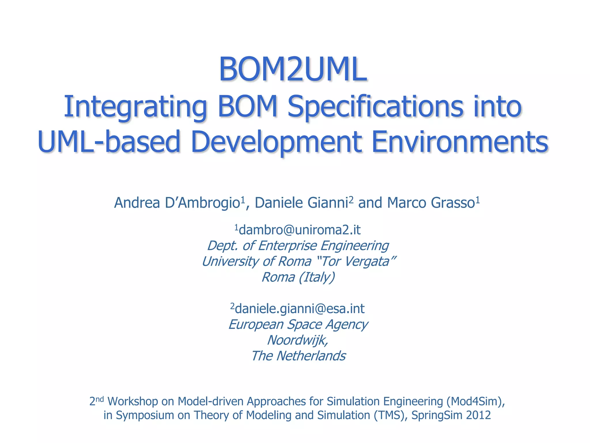
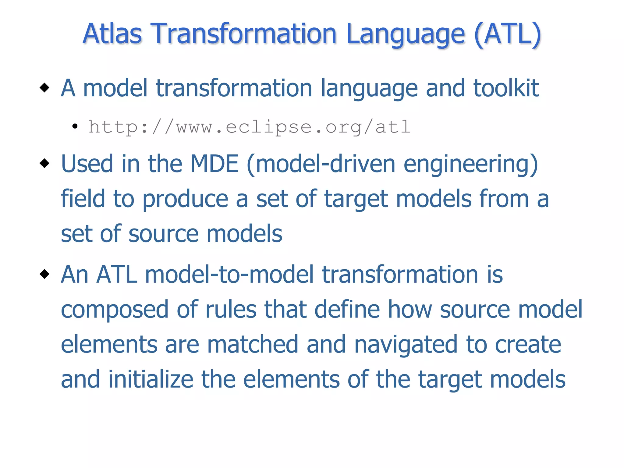
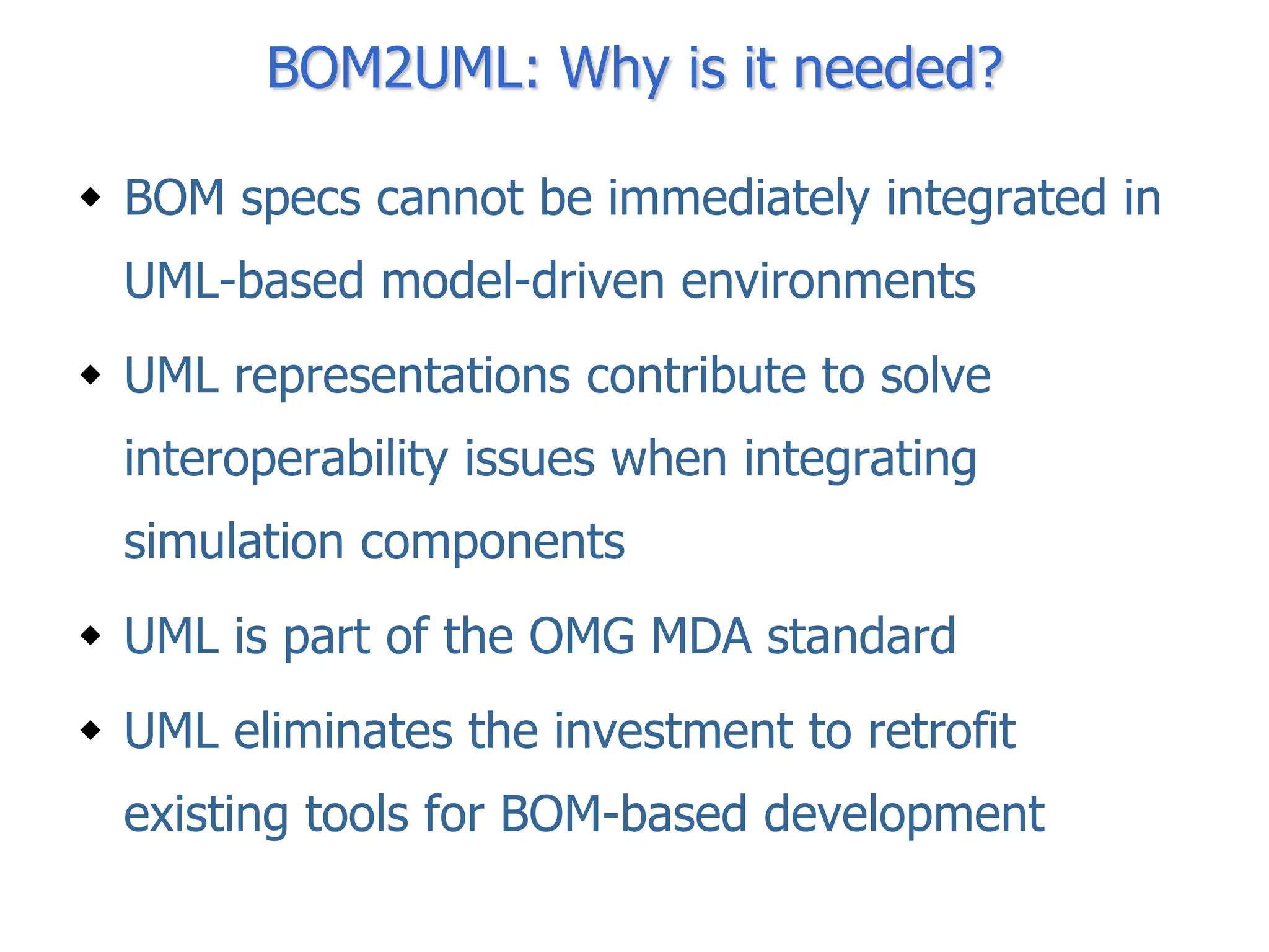
![Interaction Overview Diagram
ref
Discharge Bullet
[Faulty Bullet]
ref ref
Fire Cannon Explode Bullet
ref ref
Throw Explode
Handbomb Handbomb
[Faulty Handbomb]
ref
Discharge
Handbomb](https://image.slidesharecdn.com/mod4sim2012dambrogiogiannigrasso-120610081635-phpapp01/75/BOM2UML-Integrating-BOM-Specifications-into-UML-based-Development-Environments-19-2048.jpg)
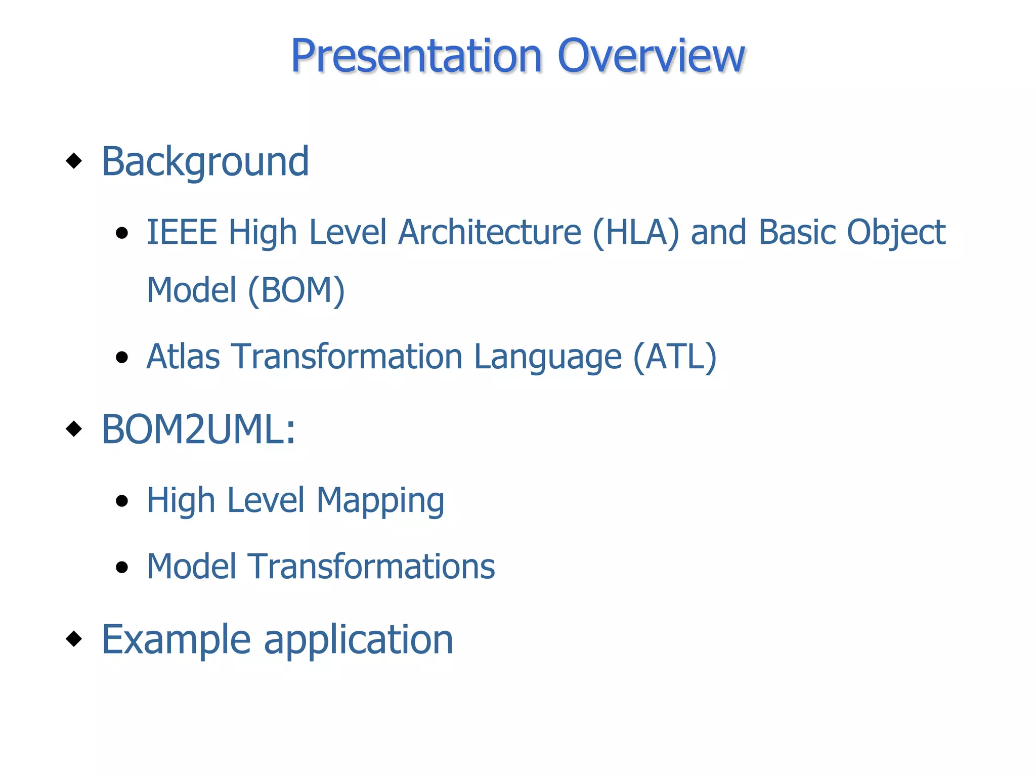
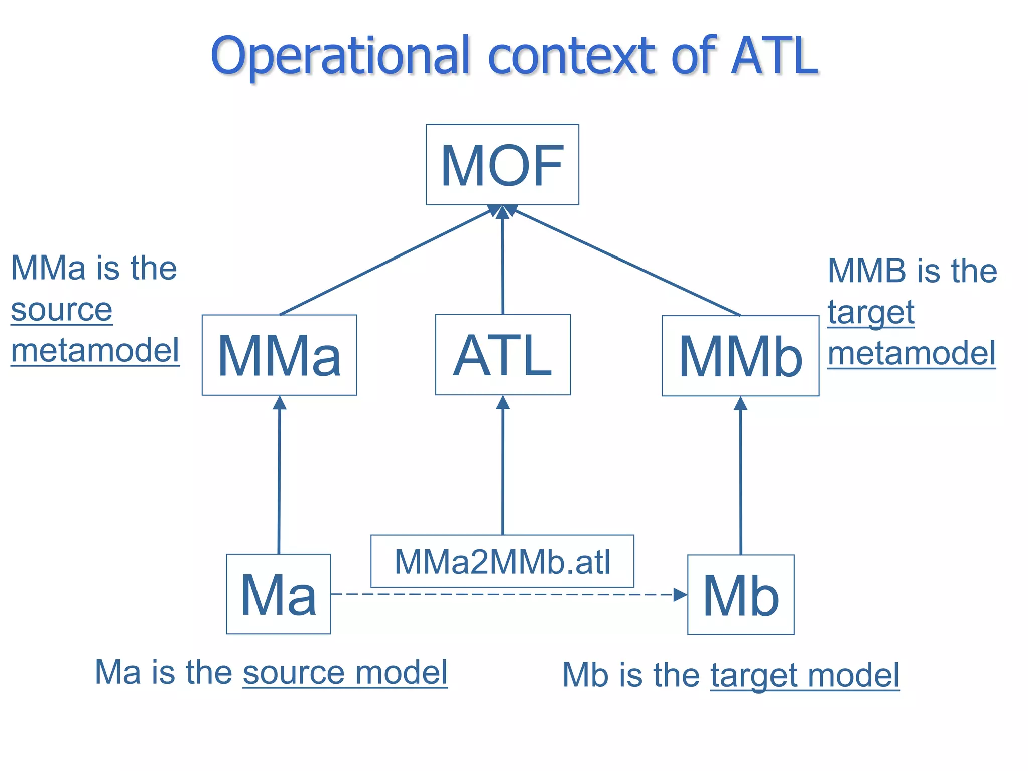
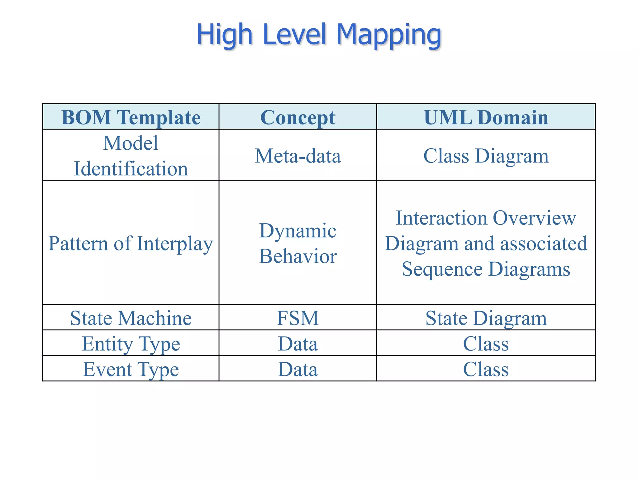
![Interaction Overview Diagram
ref
Discharge Bullet
[Faulty Bullet]
ref ref
Fire Cannon Explode Bullet
ref ref
Throw Explode
Handbomb Handbomb
[Faulty Handbomb]
The BOM Pattern of ref
Discharge
Interplay becomes an Handbomb
Interaction Overview
Diagram](https://image.slidesharecdn.com/mod4sim2012dambrogiogiannigrasso-120610081635-phpapp01/75/BOM2UML-Integrating-BOM-Specifications-into-UML-based-Development-Environments-20-2048.jpg)
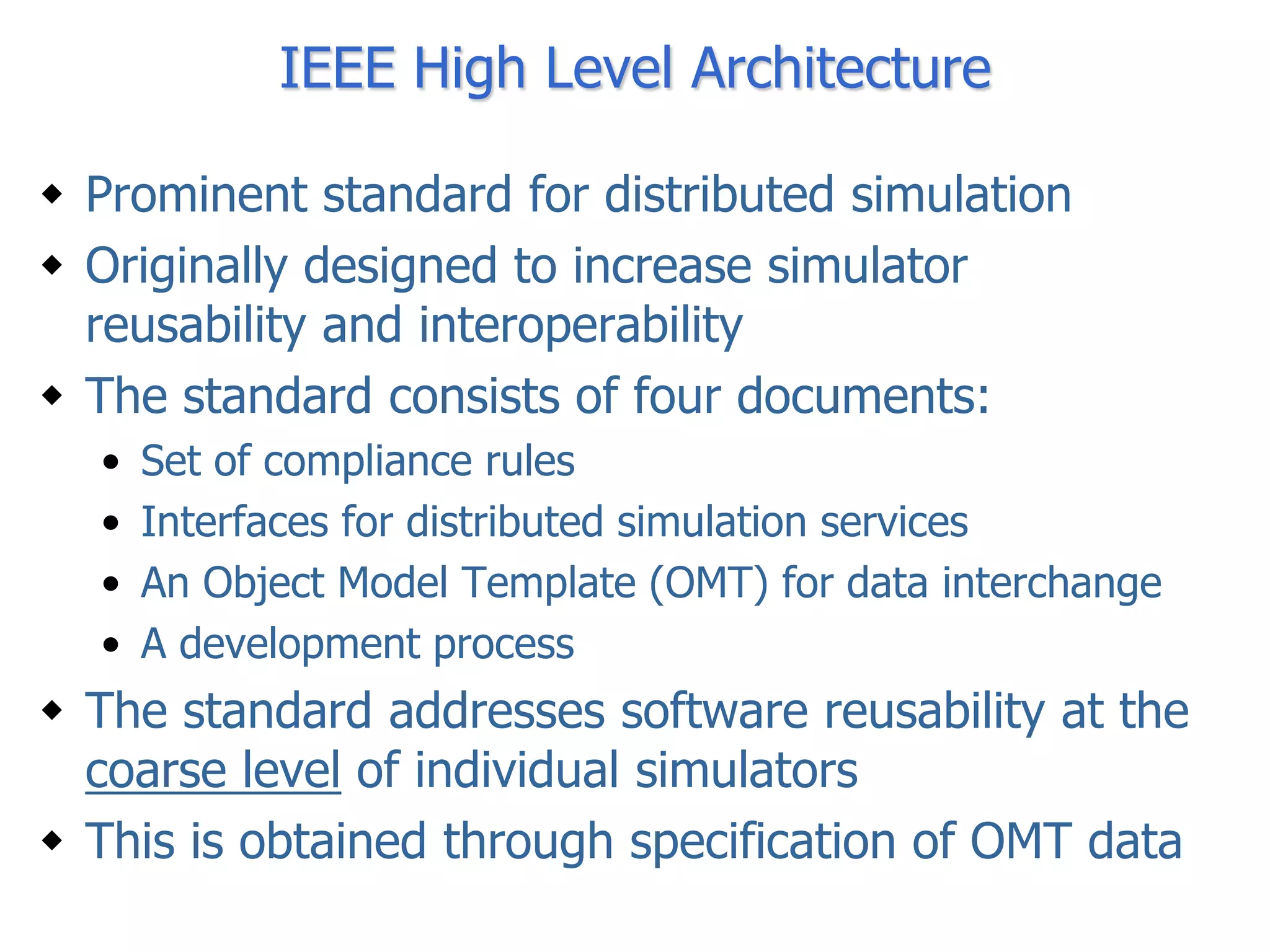
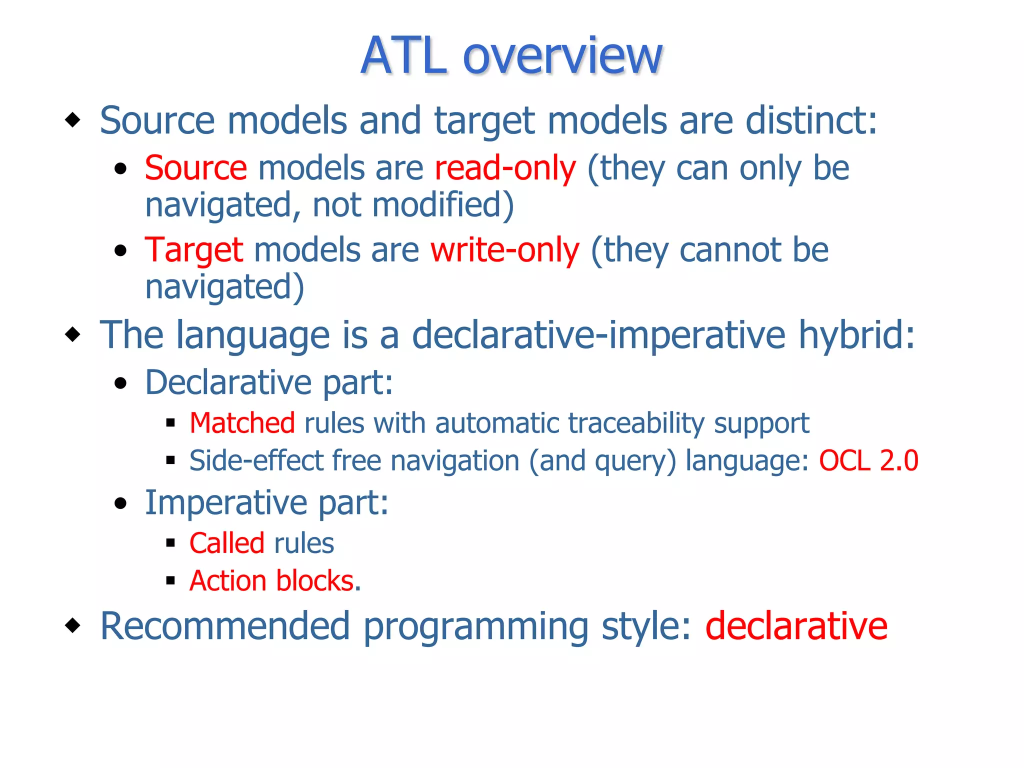
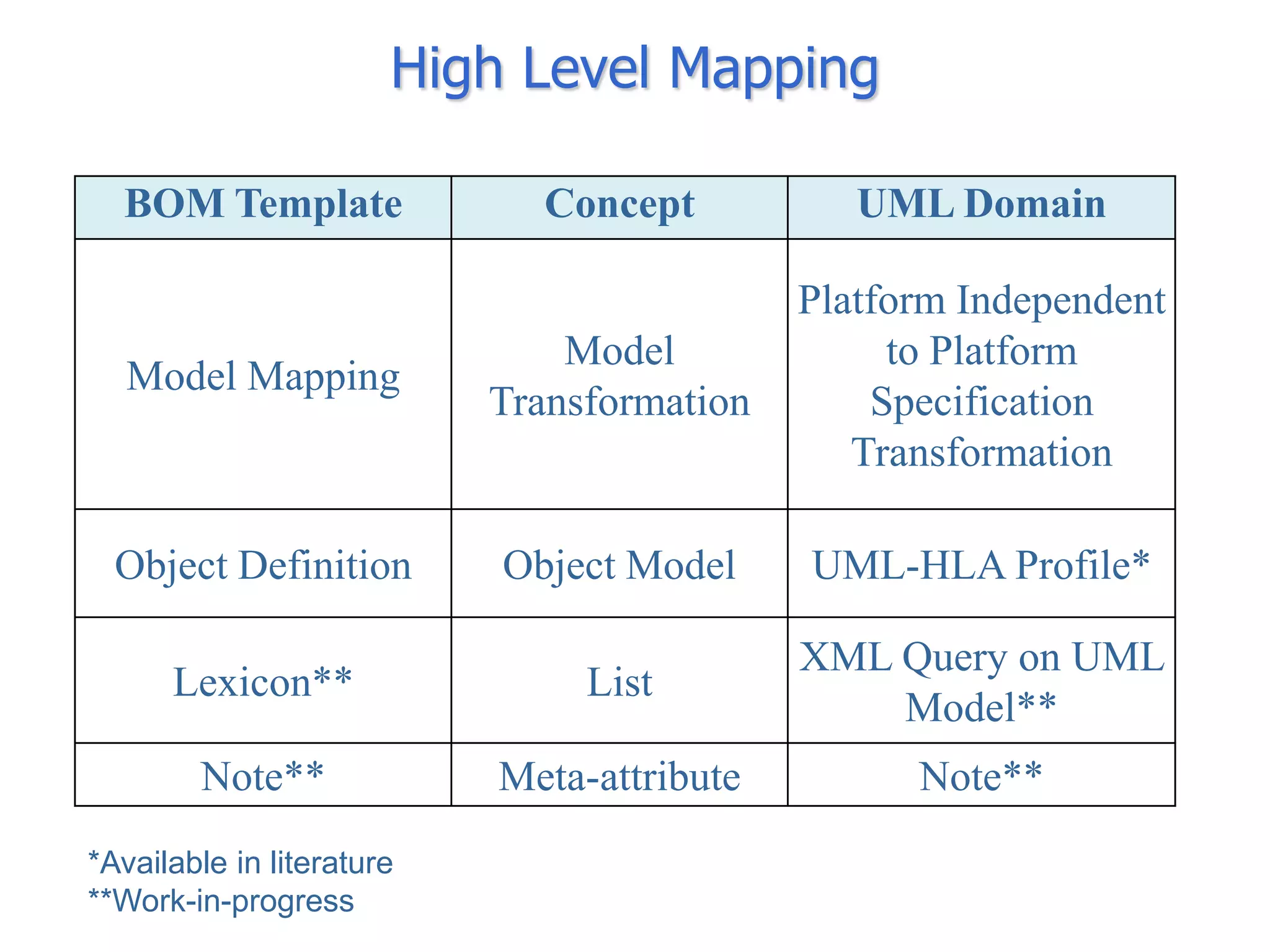
![Interaction Overview Diagram
ref
Discharge Bullet
[Faulty Bullet]
ref ref
Fire Cannon Explode Bullet
ref ref
Throw Explode
Handbomb Handbomb
[Faulty Handbomb]
ref
Discharge
Each Variation Handbomb
becomes an
“alternative” Action](https://image.slidesharecdn.com/mod4sim2012dambrogiogiannigrasso-120610081635-phpapp01/75/BOM2UML-Integrating-BOM-Specifications-into-UML-based-Development-Environments-21-2048.jpg)
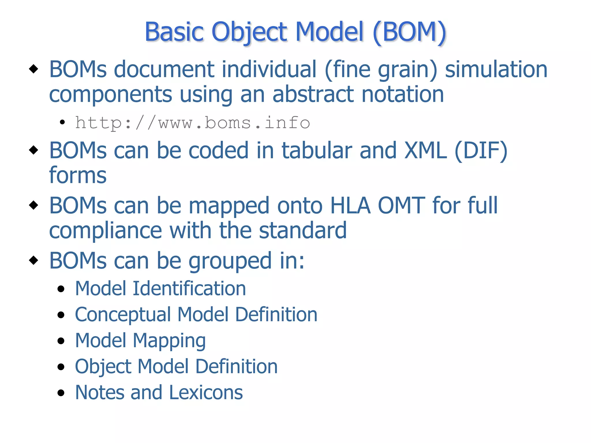
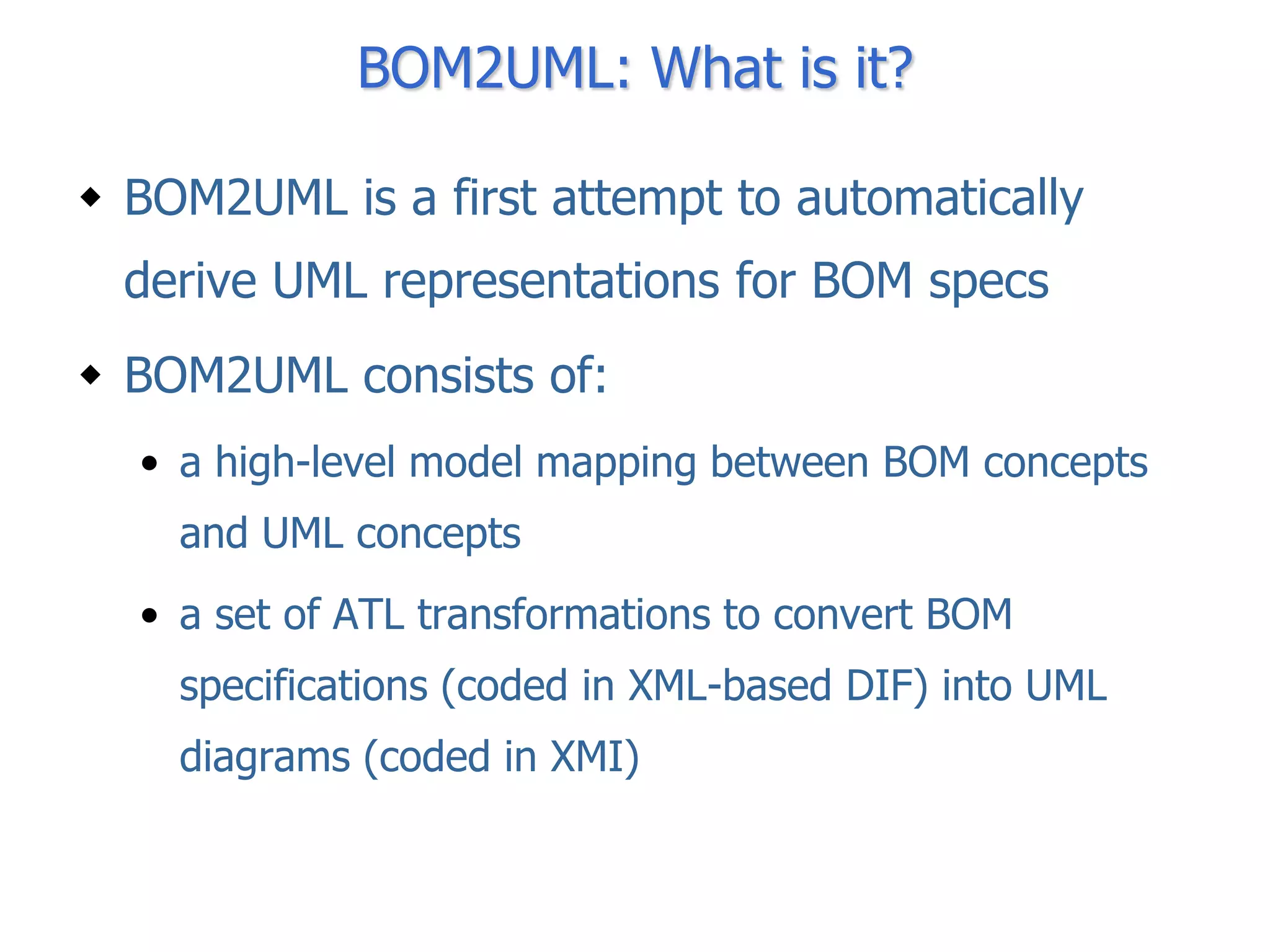
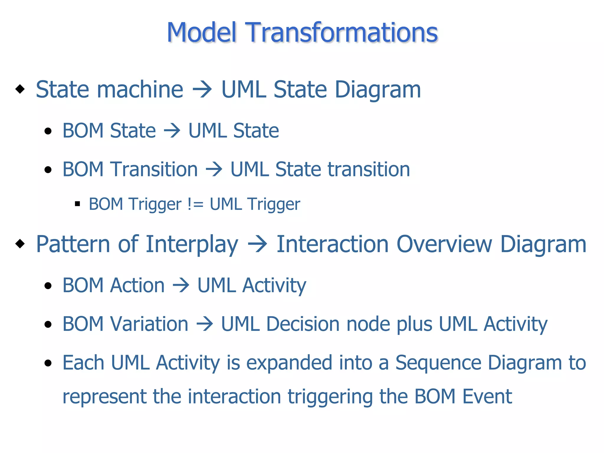
![Interaction Overview Diagram
ref
Discharge Bullet
[Faulty Bullet]
ref ref
Fire Cannon Explode Bullet
Each Action becomes
and Activity
ref ref
Throw Explode
Handbomb Handbomb
[Faulty Handbomb]
ref
Discharge
Handbomb](https://image.slidesharecdn.com/mod4sim2012dambrogiogiannigrasso-120610081635-phpapp01/75/BOM2UML-Integrating-BOM-Specifications-into-UML-based-Development-Environments-22-2048.jpg)
![Interaction Overview Diagram
Each Action is
exploded and
ref
represented as a
Discharge Bullet
Sequence Diagram
[Faulty Bullet]
ref ref
Fire Cannon Explode Bullet
ref ref
Throw Explode
Handbomb Handbomb
[Faulty Handbomb]
ref
Discharge
Handbomb](https://image.slidesharecdn.com/mod4sim2012dambrogiogiannigrasso-120610081635-phpapp01/75/BOM2UML-Integrating-BOM-Specifications-into-UML-based-Development-Environments-23-2048.jpg)
![Interaction Overview Diagram
UML Class
representing the BOM
Event [Faul
Cannon Target
ref
[firingCommand==true]
cannonshot Fire Cannon
ref
Throw
Handbomb
[Faulty](https://image.slidesharecdn.com/mod4sim2012dambrogiogiannigrasso-120610081635-phpapp01/75/BOM2UML-Integrating-BOM-Specifications-into-UML-based-Development-Environments-24-2048.jpg)
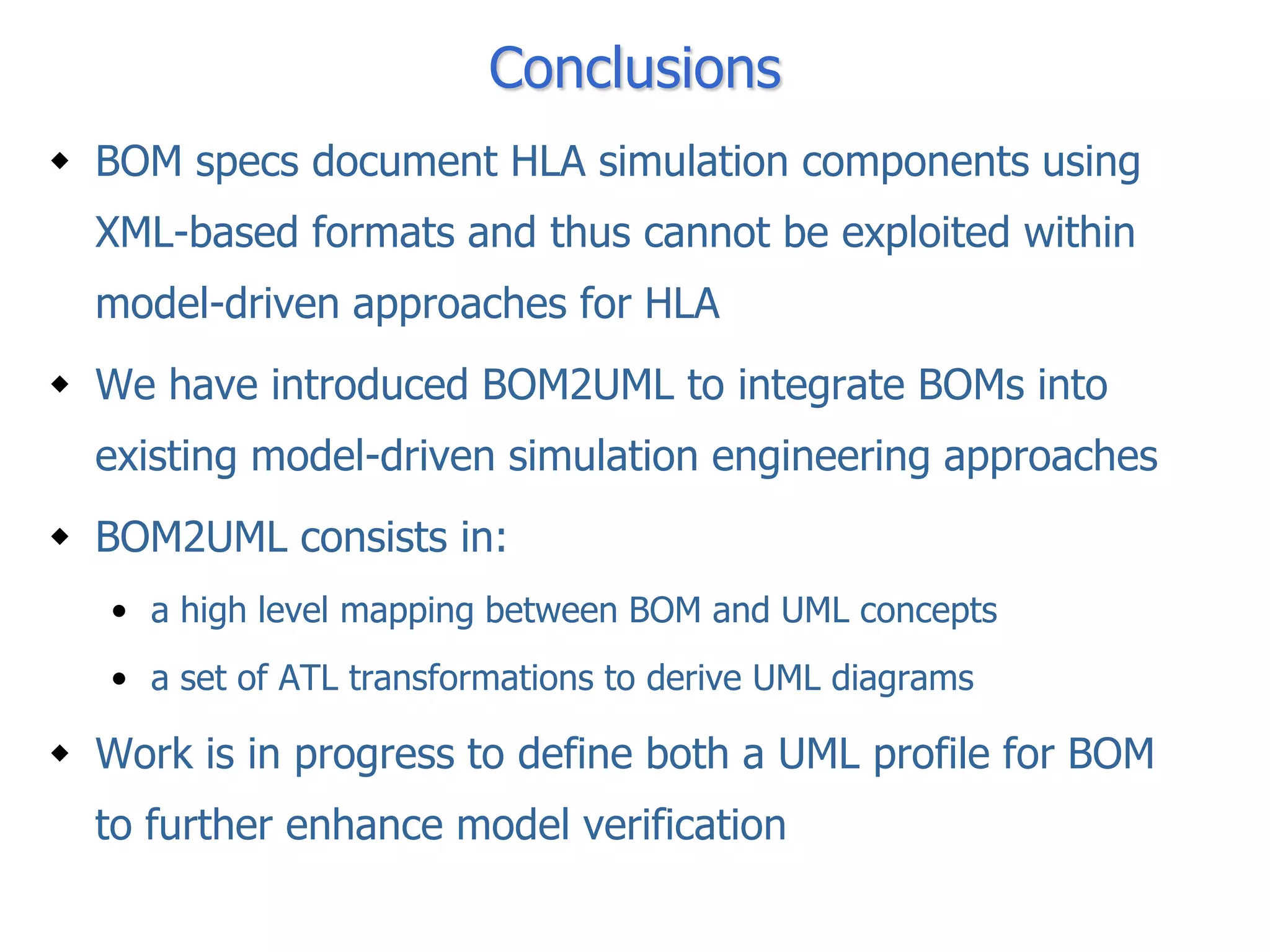

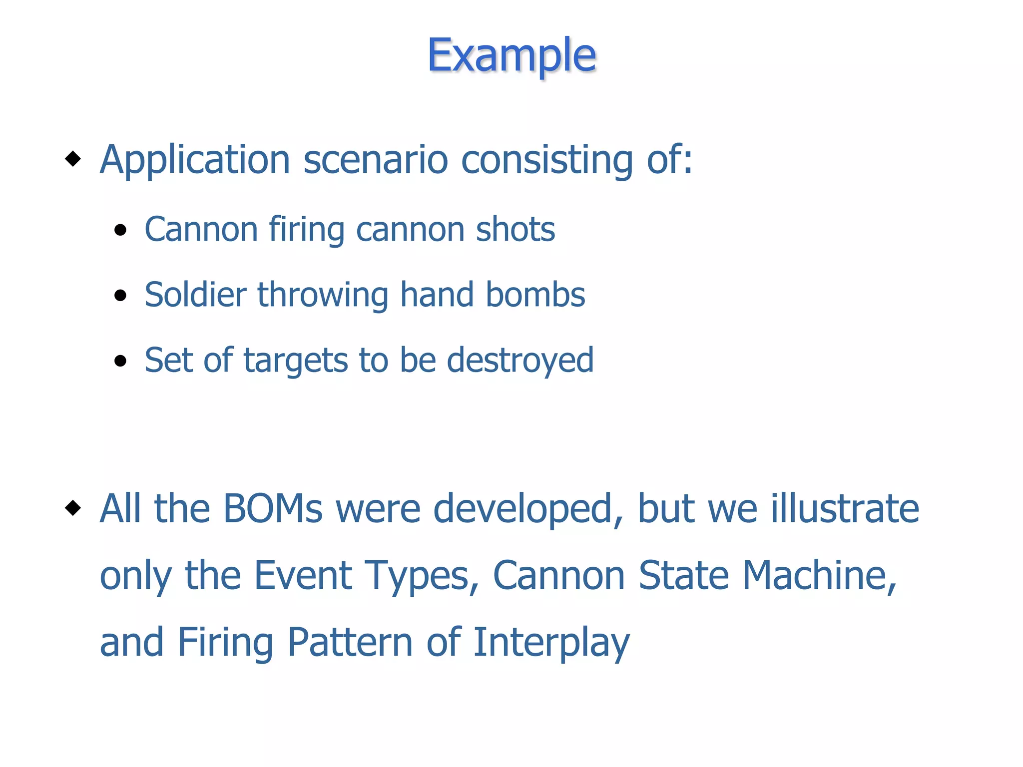
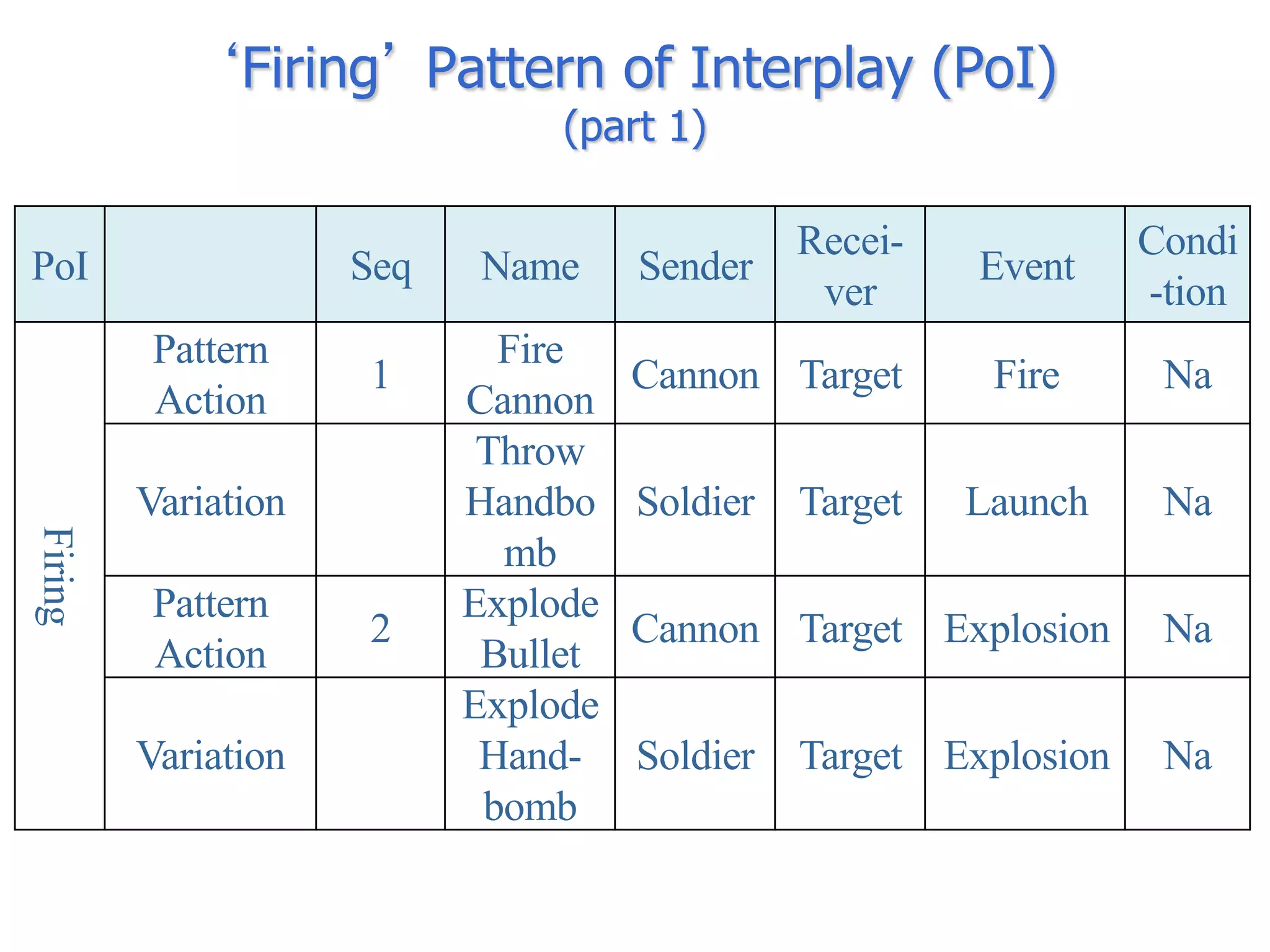
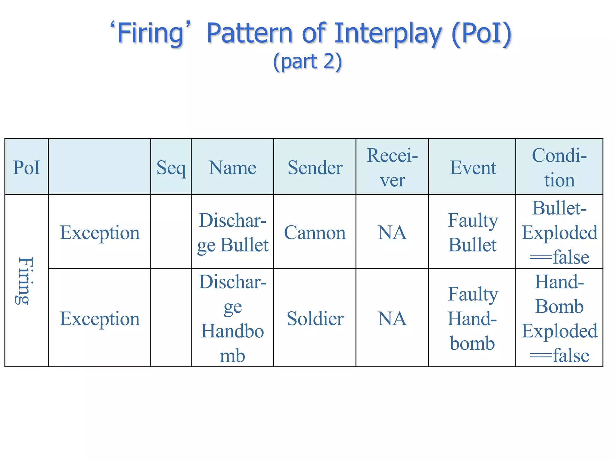
The document discusses BOM2UML, a model transformation approach that automatically derives UML representations from BOM specifications. BOM2UML includes a high-level mapping between BOM concepts and UML concepts, and a set of ATL transformations to convert BOM specifications in XML format into UML diagrams in XMI format. This integration of BOMs into model-driven engineering approaches addresses interoperability issues when combining simulation components. An example application demonstrates transforming parts of an example BOM specification, including event types, a state machine, and a pattern of interplay, into corresponding UML elements.


![Coded Agents – with UiPath SDK + LangGraph [Virtual Hands-on Workshop]](https://cdn.slidesharecdn.com/ss_thumbnails/codedagentsdeck-251215155422-5497c599-thumbnail.jpg?width=640&height=640&fit=bounds)


