Downloaded 108 times

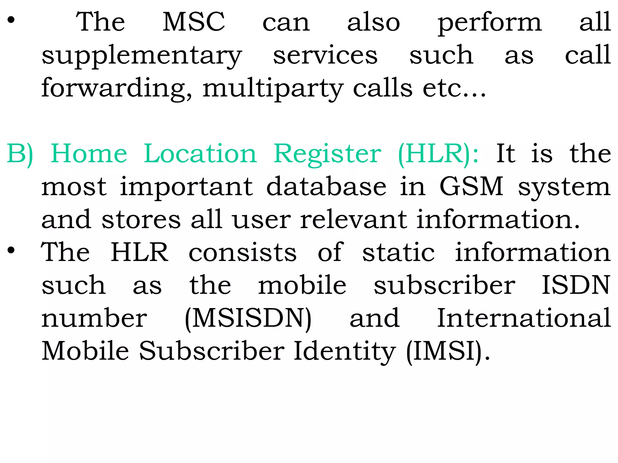
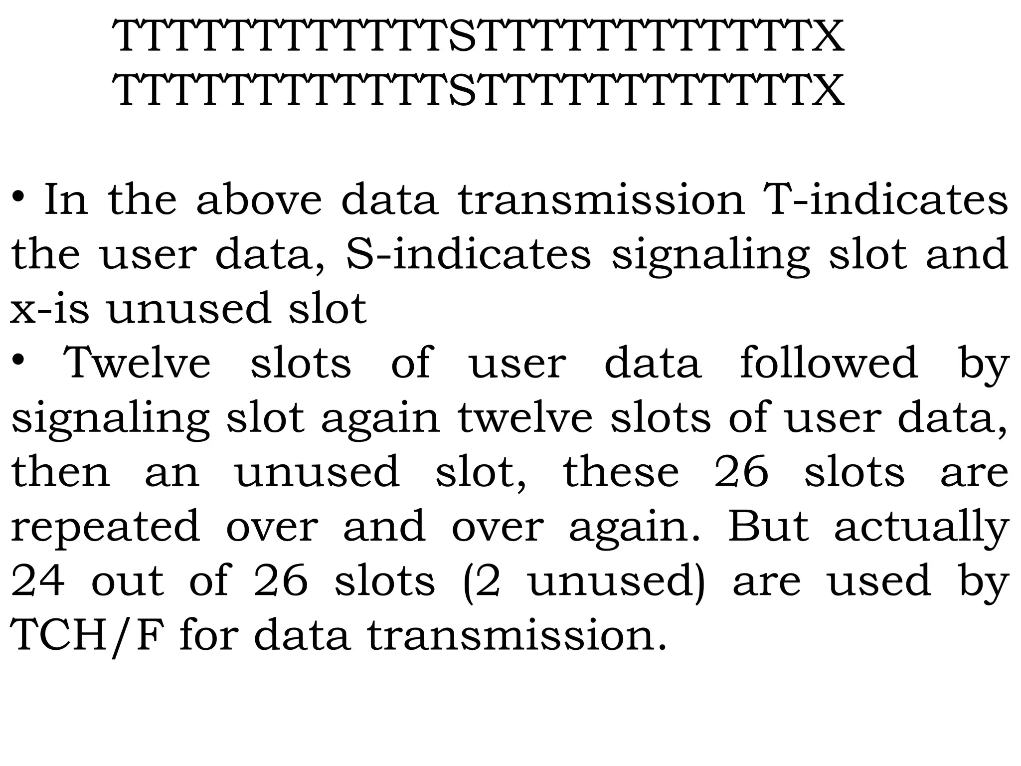
![• Here the spectrum means the set of
frequencies.
Signal Propagation Frequencies:
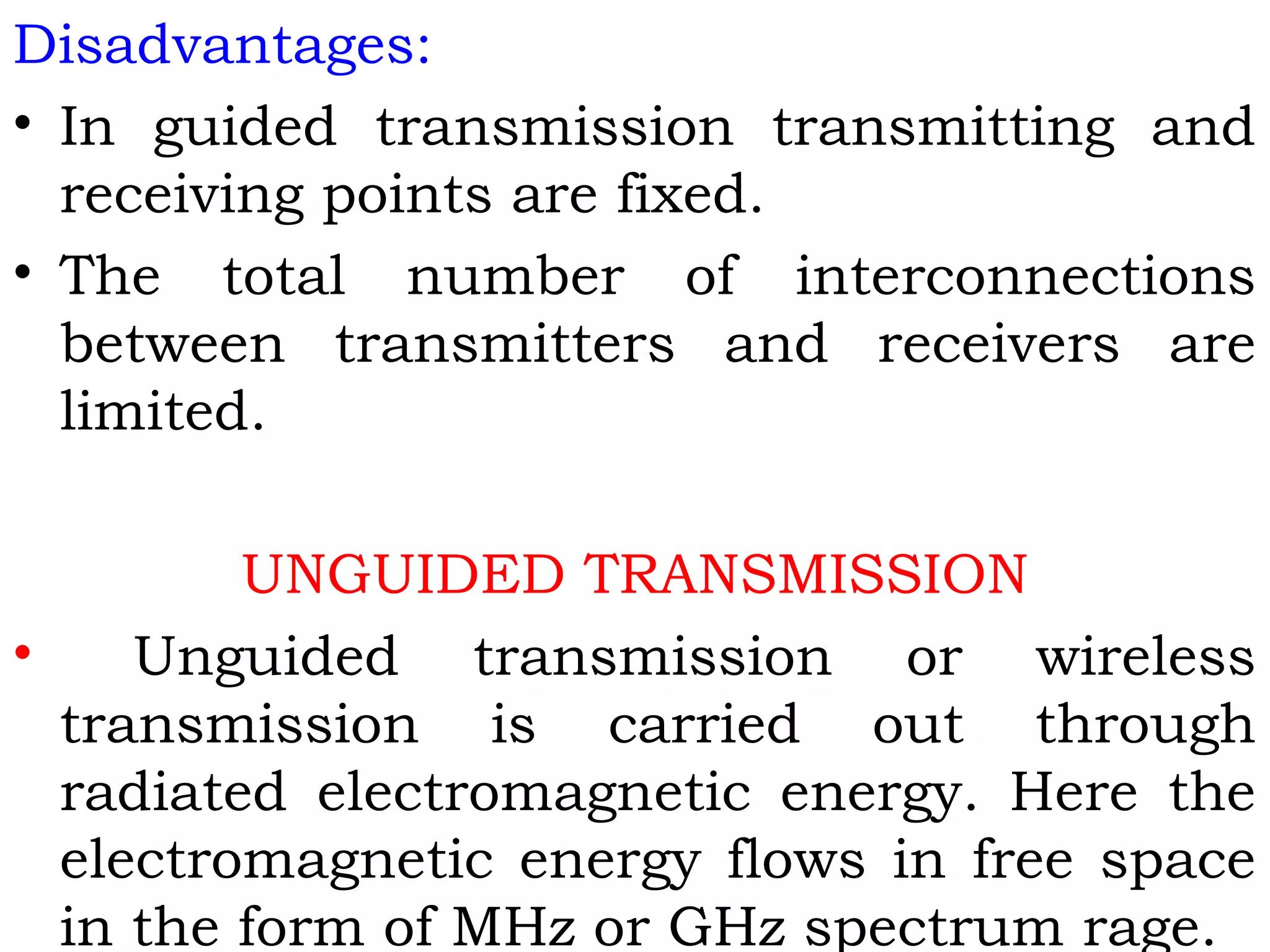
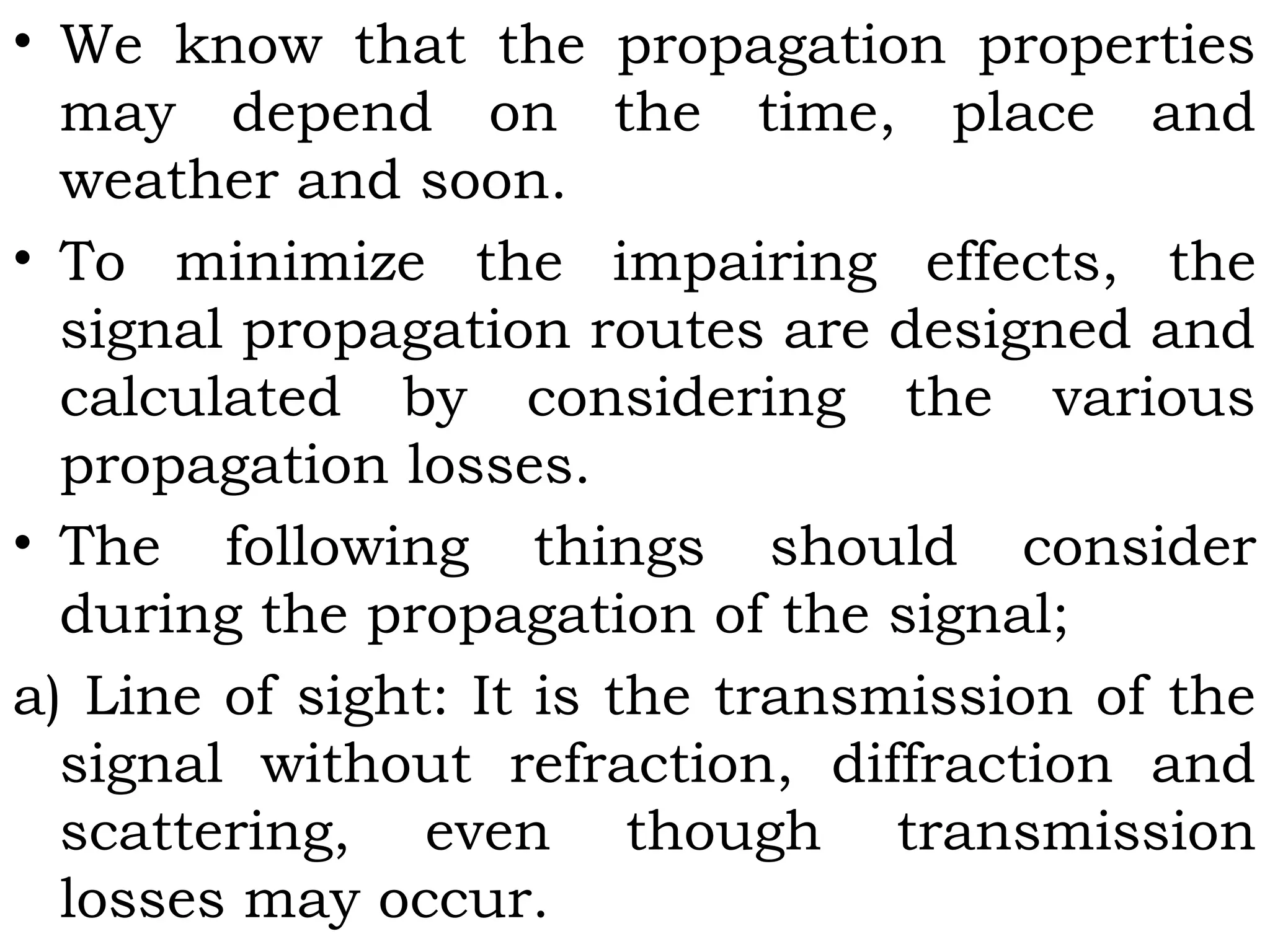
• Generally electrical signals are converted
into electromagnetic radiation and then
transmitted through antennae.
• There are various frequency bands in
electromagnetic spectrum and each of one
have different transmission requirements.
• The electromagnetic signal frequency in
vacuum or air is defined as;
f = c/λ = (300/ λ)MHz [λ in meter]](https://image.slidesharecdn.com/mc-r10-final-151002050813-lva1-app6891/75/Mobile-Computing-17-2048.jpg)
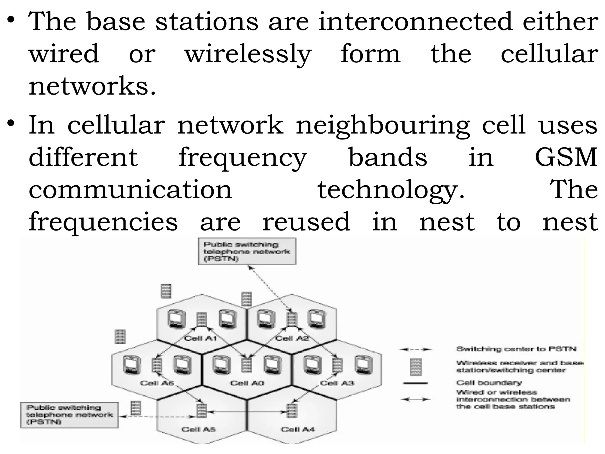
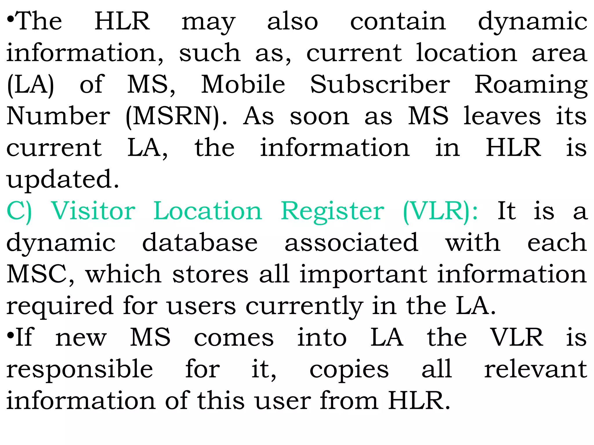
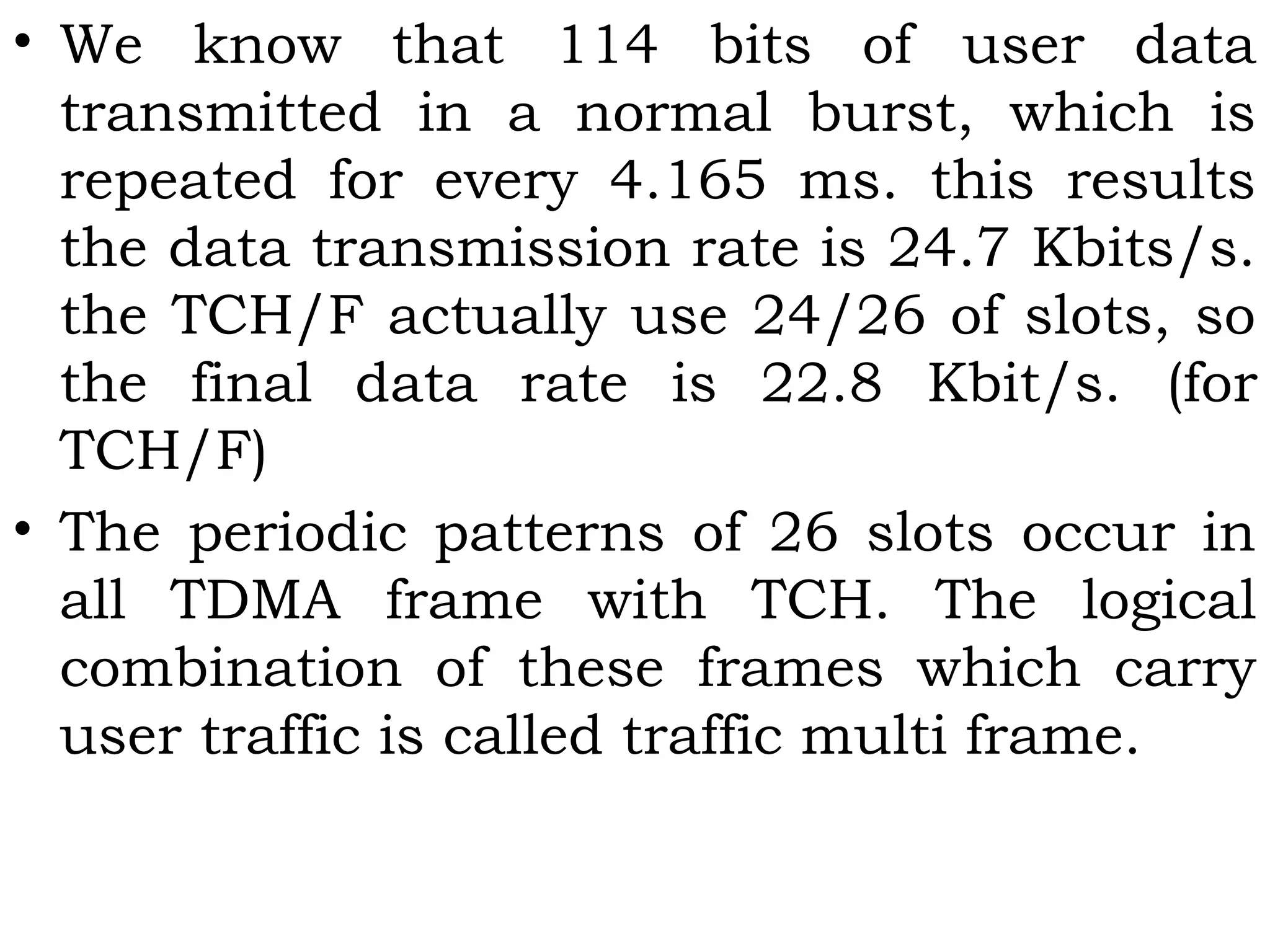
![• EGSM communication frequency spectrum lies in
three bands 900/1800/1900 MHz. this is therefore
known as tri-band.
GPRS [GSM Phase 2+ (2.5G)]: General Packet Radio
Service is a packet oriented service for data
communication of mobile devices and utilizes the
unused channels in TDMA mode in GSM network.](https://image.slidesharecdn.com/mc-r10-final-151002050813-lva1-app6891/75/Mobile-Computing-45-2048.jpg)
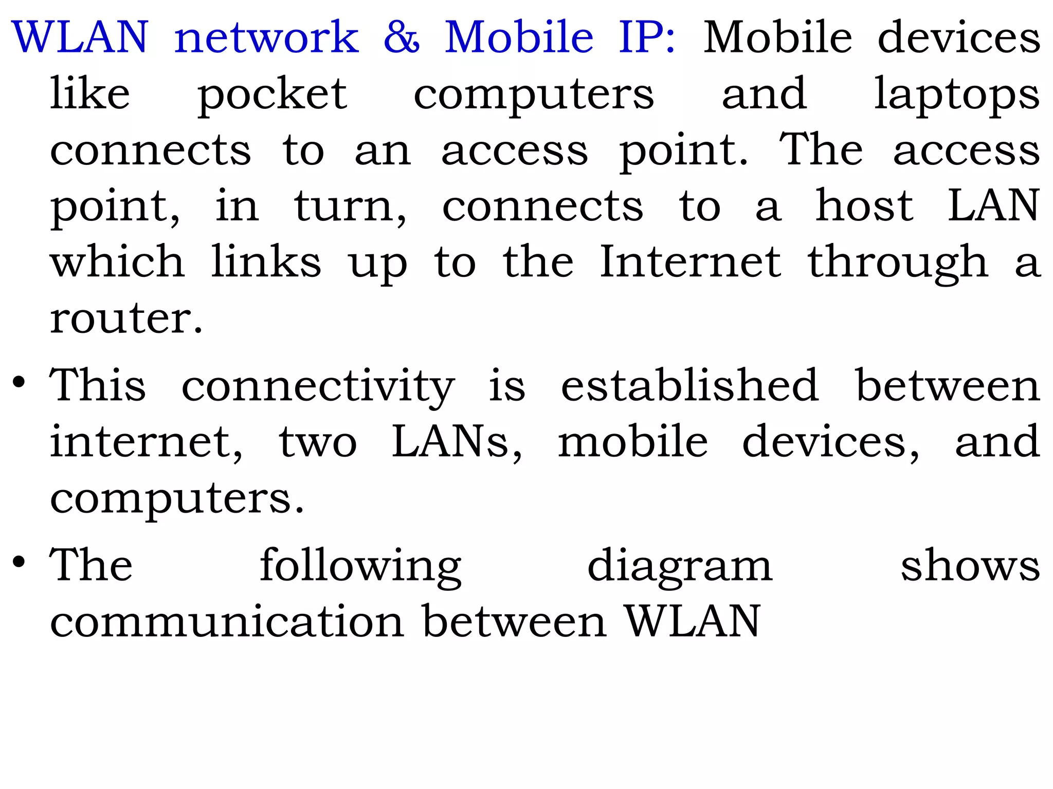
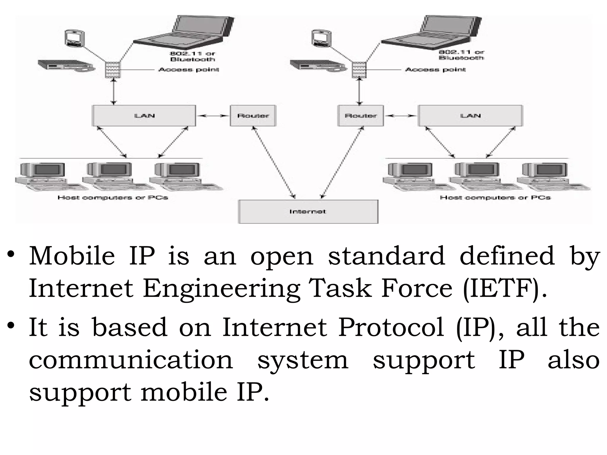


This document provides an overview of mobile computing and mobile communication. It discusses various topics including: - Types of network mobility including user and device mobility - Characteristics of communication devices from fixed/wired to mobile/wireless - Signal propagation methods including guided transmission using wires/fibers and unguided transmission using electromagnetic waves - Modulation methods and standards for voice and data communication in 1G-4G networks including GSM - Components of wireless transmission including antennas, frequencies, and modulation