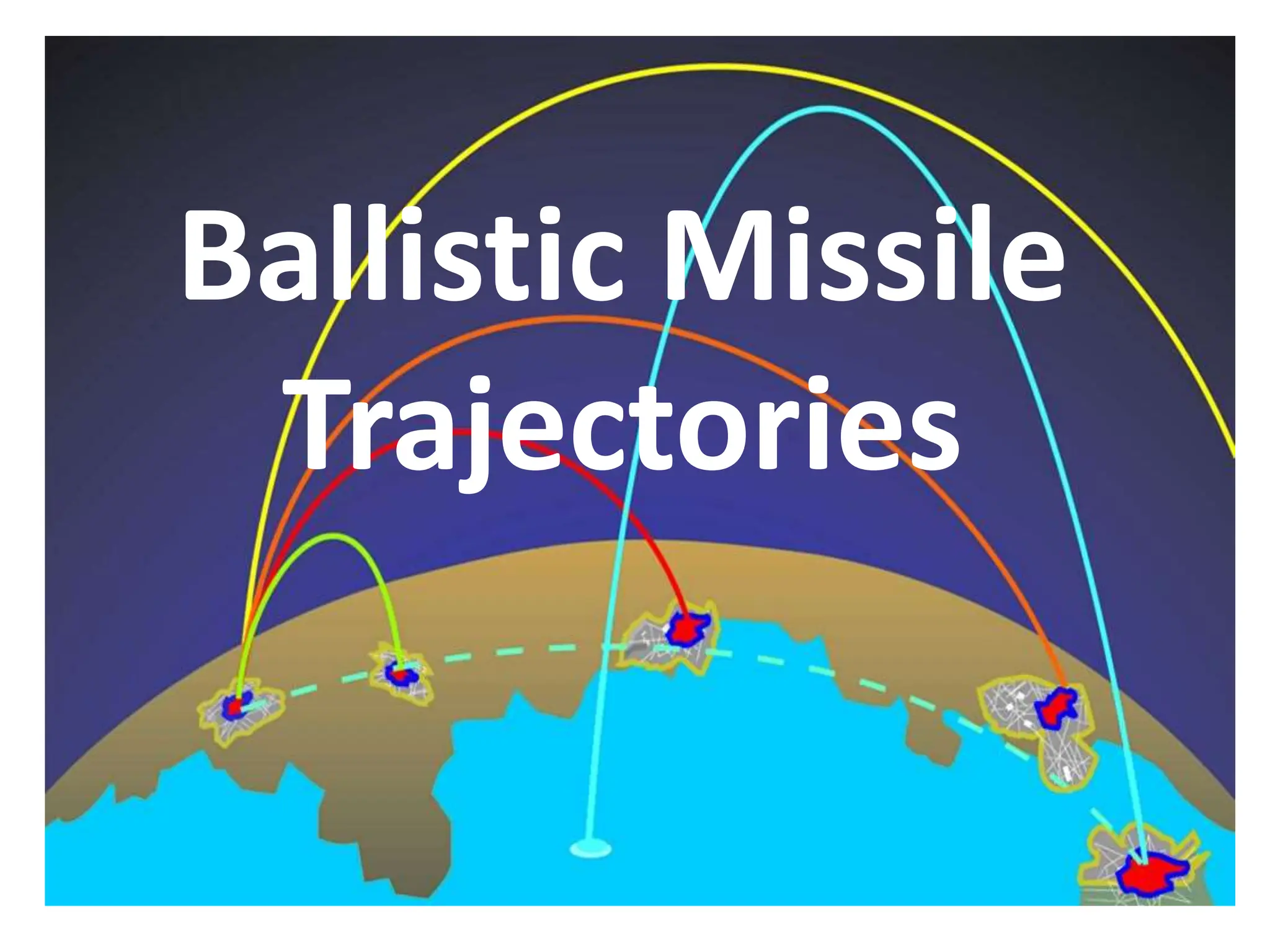
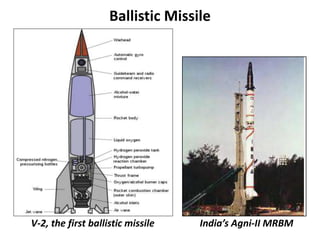
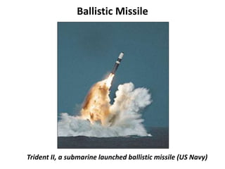
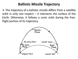
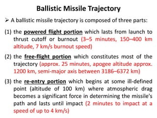
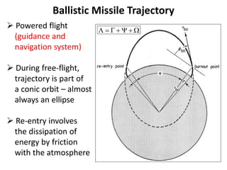
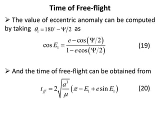
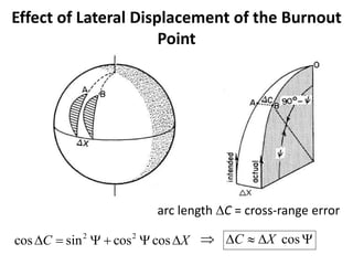
Ballistic Missile
Trajectories
Ballistic Missile
 A ballistic missile is a missile which follows a sub-orbital
flight path to a predetermined target.
 A ballistic missile is a missile that has ballistic trajectory
over most of its flight path.
 A ballistic missile can deliver one or more warheads to a
predetermined target.
 It governed by the laws of orbital mechanics and
ballistics (during a part of its entire phase).
Ballistic Missile
 Ballistic missiles are used for transportation of a payload
from one point on the Earth (launch site) to another point
on the surface of the Earth (impact point or target).
 They are accelerated to a high velocity during a relatively
short period.
 Then a re-entry vehicle, containing the warhead, is
released and this vehicle then simply coasts in a ballistic or
free-fall trajectory to the final impact point.
 To date, ballistic missiles have been propelled by
chemical rocket engines of various types.
Ballistic Missile Components
Iraq’s Scud Missile Minuteman III (US)
Categorisation of Ballistic Missile
United States
Soviet and Russian Military
Classes Range
Intercontinental Ballistic Missile (ICBM) over 5500 kilometers
Intermediate Range Ballistic Missile (IRBM) 3000 to 5500 kilometers
Medium Range Ballistic Missile (MRBM) 1000 to 3000 kilometers
Short Range Ballistic Missile (SRBM) up to 1000 kilometers
Classes Range
Strategic over 1000 kilometers
Operational Strategic 500 to 1000 kilometers
Operational 300 to 500 kilometers
Operational Tactical 50 to 300 kilometers
Tactical up to 50 kilometers
General Category of Ballistic Missile
Also,
 Submarine launched Ballistic Missile (SLBM) – ICBM range
 Quasi Ballistic Missile (Russians Iskander, India’s Shaurya) – also
called semi ballistic missile.
Classes Range
Tactical Ballistic Missile
(a) Battlefield Range Ballistic Missile (BRBM)
Between 150 to 300 kms
Less than 200 kms
Theatre Ballistic Missile (TBM)
(a) Short Range Ballistic Missile (SRBM)
(b) Medium Range Ballistic Missile (MRBM)
Between 300 to 3500 kms
1000 kms or less
Between 1000 to 3500 kms
Intermediate Range Ballistic Missile (IRBM) or
Long Range Ballistic Missile (LRBM)
Between 3500 to 5500 kms
Intercontinental Ballistic Missile (ICBM) More than 5500 kms
Ballistic Missile
V-2, the first ballistic missile India’s Agni-II MRBM
Ballistic Missile
Trident II, a submarine launched ballistic missile (US Navy)
Ballistic Missile Trajectory
 The trajectory of a ballistic missile differs from a satellite
orbit in only one respect – it intersects the surface of the
Earth. Otherwise, it follows a conic orbit during the free-
flight portion of its trajectory.
Ballistic Missile Trajectory
 A ballistic missile trajectory is composed of three parts:
(1) the powered flight portion which lasts from launch to
thrust cutoff or burnout (3–5 minutes, 150–400 km
altitude, 7 km/s burnout speed)
(2) the free-flight portion which constitutes most of the
trajectory (approx. 25 minutes, apogee altitude approx.
1200 km, semi-major axis between 3186–6372 km)
(3) the re-entry portion which begins at some ill-defined
point (altitude of 100 km) where atmospheric drag
becomes a significant force in determining the missile's
path and lasts until impact (2 minutes to impact at a
speed of up to 4 km/s)
Ballistic Missile Trajectory
 Powered flight
(guidance and
navigation system)
 During free-flight,
trajectory is part of
a conic orbit – almost
always an ellipse
 Re-entry involves
the dissipation of
energy by friction
with the atmosphere
      
Non-dimensional Parameter ‘Q’
 Here we need to define a non-dimensional parameter Q
as
(1)
 Note that the value of Q is not constant for a satellite but
varies from point to point in the orbit. (Q = 1, 2 or > 2)
 From the energy equation we can prove
(2)
2
2
cs
v v r
Q
v 
 
 
 
 
2
2 2
v
r a
 
    
2
2
r r
a or Q
Q a
  

Free-flight Range Equation
 Objective is to get a simple expression for the free-flight
range () of a missile in terms of its burnout conditions.
 Initial assumption that the Earth does not rotate and that the
altitude at which re-entry starts is the same as the burnout
altitude (symmetrical free-flight trajectory).
Since the free-flight trajectory of a missile is a conic section,
the general equation of a conic can be applied to the burnout
point.
(3)
 Solving for , we get (4)
1 cos
bo
bo
p
r
e 


cos bo
 cos bo
bo
bo
p r
r e



Free-flight Range Equation
Since , half the
free-flight range angle ()
lies on each side of the
major axis, and
(5)
And equation (4) can be
written as
(6)
Equation (6) is an expression for the free-flight range angle
in terms of p, e, and .
bo re
h h

cos cos
2
bo


 
cos
2
bo
bo
r p
r e



bo
r
Free-flight Range Equation
 Since and , we can use the
definition of parameter Q to obtain
(7)
 Now, since (8)
 Substituting equations (2) and (7) in equation (8),
we get
(9)
2
p h 
 cos
h rv 

2 2 2
2
cos
cos
r v
p rQ



 
 
2 2
1 , 1
p
p a e e
a
    
 
2 2
1 cos 2
e Q Q

  
Free-flight Range Equation
 Now substituting equations (7) and (9) into
equation (6) we have one form of the free-flight
range equation:
(10)
 Given a particular launch point and target, the
total range angle, , can be calculated. If we know
how far the missile will travel during powered flight
and re-entry, the required free-flight range angle,
, also becomes known.
 
2
2
1 cos
cos
2 1 cos 2
bo bo
bo bo bo
Q
Q Q





 
Flight path Angle Equation
 If we now specify and
for the missile, what should
the flight-path angle, , be
in order that the missile will
hit the target?
 So we have to derive an
expression for in terms of
, and .
 So we need to consider a
geometry shown here to
derive an expression for flight-path angle equation.
bo
r bo
v
bo

bo

bo
r bo
v
Flight path Angle Equation
 Let us concentrate on the triangle formed by
and the burnout
point. Let us divide
the triangle into two
right triangles by the
dashed line, d, as shown
in the right hand side
diagram.
,
F F
Flight path Angle Equation
 From previous diagram, we can express d as
(11)
and also as
(12)
 Combining the two equations (11) and (12), we
get
(13)
sin
2
bo
d r


sin 180 2
2
bo bo
d r 
  
 

  
 
 
 
 
sin 2 sin
2 2
bo
bo
bo
r
r

 
 
 
  
 
Flight path Angle Equation
 Since and from equation (2),
, we can write equation (13) as
(14)
 Equation (14) is called the flight path angle
equation.
 Low trajectory and High trajectory.
2
bo bo
r r a

 
 
2
bo bo
r a Q
 
2
sin 2 sin
2 2
bo
bo
bo
Q
Q


 
 
 
 
 
Maximum Range Trajectory
Figure: Range vs flight-path angle
Maximum Range Trajectory
 To derive expressions for the maximum range condition,
a simpler method is to see under what conditions the
flight-path angle equation yields a single solution.
 If the right side of equation (14) equals exactly 1, we get
only a single answer for . This must, then, be the
maximum range condition.
(15)
(16)
for maximum range conditions only.
bo

 
2
sin 2 sin 1
2 2
1
2 90 180
2 4
bo
bo
bo
bo bo
Q
Q

 

 
 
  
 
 

      
Maximum Range Trajectory
 From equation (15) we can easily find the
maximum range angle attainable with a given .
(17)
for maximum range conditions.
 Solving for , we get
(18)
for maximum range conditions.
bo
Q
sin
2 2
bo
bo
Q
Q



bo
Q
 
 
2sin 2
1 sin 2
bo
Q


 
Time of Free-flight
Time of Free-flight
 The value of eccentric anomaly can be computed
by taking as
(19)
 And the time of free-flight can be obtained from
(20)
1 180 2
   
 
 
1
cos 2
cos
1 cos 2
e
E
e
 

 
 
3
1 1
2 sin
ff
a
t E e E


  
Effect of launching errors
on Free-flight Range
Effect of Launching errors on Range
 Variations in the speed, position, and launch
direction of the missile at thrust cutoff will produce
errors at the impact point.
These errors are of two types – errors in the
intended plane which cause either a long or a short
hit, and out-of-plane errors which cause the missile
to hit to the right or left of the target.
 We will refer to errors in the intended plane as
"down-range" errors, and out-of-plane errors as
"cross-range" errors.
Cross-Range and Down-Range Errors
 There are two possible sources of cross-range error:
(1) Lateral displacement of the burnout point.
(2) Incorrect Launch Azimuth.
 And the sources of down-range error are:
(1) Down-range displacement of the burnout point.
(2) Errors in burnout flight-path angle.
(3) Incorrect burnout height.
(4) Incorrect speed at burnout.
Effect of Lateral Displacement of the Burnout
Point
arc length DC = cross-range error
2 2
cos sin cos cos
C X
D     D  cos
C X
D  D 
Cross-range Error due to Incorrect Launch Azimuth
 If the actual launch azimuth differs from the intended
launch azimuth by an amount, Db, a cross-range error, DC,
will result.
2 2
cos cos sin cos
C b
D     D
sin
C b
D  D 
Effect of Down-Range Displacement of the
Burnout Point
 An error in down-range position at thrust cutoff
produces an equal error at impact.
If the actual burnout point is 1 nm farther down-
range than was intended, the missile will overshoot
the target by exactly 1 nm.
Effect of burnout flight-path angle errors on range
 In the above graph D will represent a down-
range error causing the missile to undershoot or
overshoot the target.
Effect of burnout flight-path angle errors on range
 A good approximate value for D for very small
values of is given by
(25)
where is the slope of the curve at the point
corresponding to the intended trajectory.
bo

D
bo
bo



D  D

bo



Effect of burnout flight-path angle errors on range
 The expression for may be obtained by
implicit partial differentiation of the free-flight
range equation.
 The free-flight range equation can be converted
into an alternate form for the simple differentiation.
 Recall the free-flight range equation
bo



 
2
2
1 cos
cos
2 1 cos 2
bo bo
bo bo bo
Q
Q Q





 
Effect of burnout flight-path angle errors on range
 Let us consider the numerator of equation (10) as
a and denominator as b.
Then .
Substituting for a and b we get
But , therefore,
2 2
cos cot
2 2
and
a a
b b a
 
 

2
1 cos sin
bo bo
 
 
2
2
1 cos
cot
2 cos 1 cos
bo bo
bo bo bo
Q
Q

 




2
1 cos
cot
2 cos sin
bo bo
bo bo bo
Q
Q

 



Effect of burnout flight-path angle errors on range
 Since we can further
simplify to obtain
Now express the above equation in terms of
and ,
(26)
Now we can differentiate equation (26) implicitly
with respect to , considering as constants.
sin 2 2cos sin ,
x x x

2
cot csc2 cot
2
bo bo
bo
Q
 

 
,
bo bo
r v
bo

2
2
cot csc2 cot
2
bo bo
bo bo
v r

 

 
bo
 ,
bo bo
r v
Effect of burnout flight-path angle errors on range
(27)
 This partial derivative is called an influence
coefficient since it influences the size of the range
error resulting from a particular burnout error.
 Therefore the free-flight range error due to
burnout flight-path angle error is given by
(28)
 
2sin 2
2
sin 2
bo
bo bo

 
 

  

 
2sin 2
2
sin 2
bo
bo
bo



 
 
D   D
 
 
Down-Range Errors caused by Incorrect Burnout
Height
 Again a good approximate value for D for very
small values of is given by
 Again differentiating the equation (26) implicitly
with respect to , and solving for , we get
(29)
bo
r
D
bo
bo
r
r

D  D

bo
r
bo
r


2
2 2
sin
4 2
sin 2
bo bo bo bo
r v r






Down-Range Errors caused by Incorrect Speed at
Burnout
 A good approximate value for D for very small
values of is given by
 Again differentiating the equation (26) implicitly
with respect to , and solving for , we get
(30)
bo
v
D
bo
bo
v
v

D  D

bo
v


bo
v
2
3
sin
8 2
sin 2
bo bo bo bo
v v r






Total Down-Range Error
 Now the total down range-error is given by
TOTAL bo bo bo
bo bo bo
r v
r v


  
D  D  D  D
  
Effect of Earth Rotation
 The Earth rotates once on its axis in 23 hrs 56 min
producing a surface velocity at the equator of approx 0.465
km/sec (or 1524 ft/sec). The rotation is from west to east.
 The free-flight portion of a ballistic missile trajectory is
inertial in character. That is, it remains fixed in the XYZ
inertial frame while the Earth runs under it.
 Relative to this inertial XYZ frame, both the launch point
and the target are in motion.
 Thus we need to compensate for motion of the launch
site and the motion of the target due to earth rotation.
Compensating for the Initial Velocity of the Missile
 We can express the speed of any launch point on
the surface of the earth as
Vo = 1524 cos L0 (ft/sec)
Compensating for the Initial Velocity of the Missile
 The north, east, and up components of the true
velocity v can be obtained as
 Now the true velocity, flight-path angle, and
azimuth can then be found from
0
cos cos
cos sin
sin
N e e e
E e e e
Z e e
v v
v v v
v v
 b
 b


 

2 2 2
sin ; tan
N E Z
Z E N
v v v v
v v v v
 b
  
 
Compensating for Movement of the Target
Figure: Launch site and aiming point at the instant of launch
Compensating for Movement of the Target
 The angle formed at O is just the difference in
longitude between the launch point and the aiming
point, , where DN is the difference in
longitude between launch point and target.
By considering the launch azimuth, b in the
spherical triangle,
N t
 
D 
 
0 0
cos sin sin cos cos cos
t t
L L L L N t
 
    D 
0 0
0
0
sin sin cos cos sin cos
sin sin cos
cos
cos sin
t
t
L L L
L L
L
b
b
   
 
 

References
 Roger R. Bate, Donald D. Mueller, Jerry E. White,
Fundamentals of Astrodynamics, Dover Publications, 1971.
 Bibhuti Ranjan, Devashish Bhatnagar, Himanshu Bankoti,
“Exit and Re-entry of Ballistic Missile”, A project Report,
University of Petroleum & Energy Studies, April 2011.
 F. A. Abd El-Salam, S. E. Abd El-Bar, “Computation of the
Different Errors in the Ballistic Missiles Range”, ISRN
Applied Mathematics, Volume 2011, Article ID 349737,
2011.

13875446-Ballistic Missile Trajectories.ppt

  • 1.
  • 2.
    Ballistic Missile  Aballistic missile is a missile which follows a sub-orbital flight path to a predetermined target.  A ballistic missile is a missile that has ballistic trajectory over most of its flight path.  A ballistic missile can deliver one or more warheads to a predetermined target.  It governed by the laws of orbital mechanics and ballistics (during a part of its entire phase).
  • 3.
    Ballistic Missile  Ballisticmissiles are used for transportation of a payload from one point on the Earth (launch site) to another point on the surface of the Earth (impact point or target).  They are accelerated to a high velocity during a relatively short period.  Then a re-entry vehicle, containing the warhead, is released and this vehicle then simply coasts in a ballistic or free-fall trajectory to the final impact point.  To date, ballistic missiles have been propelled by chemical rocket engines of various types.
  • 4.
    Ballistic Missile Components Iraq’sScud Missile Minuteman III (US)
  • 5.
    Categorisation of BallisticMissile United States Soviet and Russian Military Classes Range Intercontinental Ballistic Missile (ICBM) over 5500 kilometers Intermediate Range Ballistic Missile (IRBM) 3000 to 5500 kilometers Medium Range Ballistic Missile (MRBM) 1000 to 3000 kilometers Short Range Ballistic Missile (SRBM) up to 1000 kilometers Classes Range Strategic over 1000 kilometers Operational Strategic 500 to 1000 kilometers Operational 300 to 500 kilometers Operational Tactical 50 to 300 kilometers Tactical up to 50 kilometers
  • 6.
    General Category ofBallistic Missile Also,  Submarine launched Ballistic Missile (SLBM) – ICBM range  Quasi Ballistic Missile (Russians Iskander, India’s Shaurya) – also called semi ballistic missile. Classes Range Tactical Ballistic Missile (a) Battlefield Range Ballistic Missile (BRBM) Between 150 to 300 kms Less than 200 kms Theatre Ballistic Missile (TBM) (a) Short Range Ballistic Missile (SRBM) (b) Medium Range Ballistic Missile (MRBM) Between 300 to 3500 kms 1000 kms or less Between 1000 to 3500 kms Intermediate Range Ballistic Missile (IRBM) or Long Range Ballistic Missile (LRBM) Between 3500 to 5500 kms Intercontinental Ballistic Missile (ICBM) More than 5500 kms
  • 7.
    Ballistic Missile V-2, thefirst ballistic missile India’s Agni-II MRBM
  • 8.
    Ballistic Missile Trident II,a submarine launched ballistic missile (US Navy)
  • 9.
    Ballistic Missile Trajectory The trajectory of a ballistic missile differs from a satellite orbit in only one respect – it intersects the surface of the Earth. Otherwise, it follows a conic orbit during the free- flight portion of its trajectory.
  • 10.
    Ballistic Missile Trajectory A ballistic missile trajectory is composed of three parts: (1) the powered flight portion which lasts from launch to thrust cutoff or burnout (3–5 minutes, 150–400 km altitude, 7 km/s burnout speed) (2) the free-flight portion which constitutes most of the trajectory (approx. 25 minutes, apogee altitude approx. 1200 km, semi-major axis between 3186–6372 km) (3) the re-entry portion which begins at some ill-defined point (altitude of 100 km) where atmospheric drag becomes a significant force in determining the missile's path and lasts until impact (2 minutes to impact at a speed of up to 4 km/s)
  • 11.
    Ballistic Missile Trajectory Powered flight (guidance and navigation system)  During free-flight, trajectory is part of a conic orbit – almost always an ellipse  Re-entry involves the dissipation of energy by friction with the atmosphere       
  • 12.
    Non-dimensional Parameter ‘Q’ Here we need to define a non-dimensional parameter Q as (1)  Note that the value of Q is not constant for a satellite but varies from point to point in the orbit. (Q = 1, 2 or > 2)  From the energy equation we can prove (2) 2 2 cs v v r Q v          2 2 2 v r a        2 2 r r a or Q Q a    
  • 13.
    Free-flight Range Equation Objective is to get a simple expression for the free-flight range () of a missile in terms of its burnout conditions.  Initial assumption that the Earth does not rotate and that the altitude at which re-entry starts is the same as the burnout altitude (symmetrical free-flight trajectory). Since the free-flight trajectory of a missile is a conic section, the general equation of a conic can be applied to the burnout point. (3)  Solving for , we get (4) 1 cos bo bo p r e    cos bo  cos bo bo bo p r r e   
  • 14.
    Free-flight Range Equation Since, half the free-flight range angle () lies on each side of the major axis, and (5) And equation (4) can be written as (6) Equation (6) is an expression for the free-flight range angle in terms of p, e, and . bo re h h  cos cos 2 bo     cos 2 bo bo r p r e    bo r
  • 15.
    Free-flight Range Equation Since and , we can use the definition of parameter Q to obtain (7)  Now, since (8)  Substituting equations (2) and (7) in equation (8), we get (9) 2 p h   cos h rv   2 2 2 2 cos cos r v p rQ        2 2 1 , 1 p p a e e a        2 2 1 cos 2 e Q Q    
  • 16.
    Free-flight Range Equation Now substituting equations (7) and (9) into equation (6) we have one form of the free-flight range equation: (10)  Given a particular launch point and target, the total range angle, , can be calculated. If we know how far the missile will travel during powered flight and re-entry, the required free-flight range angle, , also becomes known.   2 2 1 cos cos 2 1 cos 2 bo bo bo bo bo Q Q Q       
  • 17.
    Flight path AngleEquation  If we now specify and for the missile, what should the flight-path angle, , be in order that the missile will hit the target?  So we have to derive an expression for in terms of , and .  So we need to consider a geometry shown here to derive an expression for flight-path angle equation. bo r bo v bo  bo  bo r bo v
  • 18.
    Flight path AngleEquation  Let us concentrate on the triangle formed by and the burnout point. Let us divide the triangle into two right triangles by the dashed line, d, as shown in the right hand side diagram. , F F
  • 19.
    Flight path AngleEquation  From previous diagram, we can express d as (11) and also as (12)  Combining the two equations (11) and (12), we get (13) sin 2 bo d r   sin 180 2 2 bo bo d r                   sin 2 sin 2 2 bo bo bo r r            
  • 20.
    Flight path AngleEquation  Since and from equation (2), , we can write equation (13) as (14)  Equation (14) is called the flight path angle equation.  Low trajectory and High trajectory. 2 bo bo r r a      2 bo bo r a Q   2 sin 2 sin 2 2 bo bo bo Q Q            
  • 21.
    Maximum Range Trajectory Figure:Range vs flight-path angle
  • 22.
    Maximum Range Trajectory To derive expressions for the maximum range condition, a simpler method is to see under what conditions the flight-path angle equation yields a single solution.  If the right side of equation (14) equals exactly 1, we get only a single answer for . This must, then, be the maximum range condition. (15) (16) for maximum range conditions only. bo    2 sin 2 sin 1 2 2 1 2 90 180 2 4 bo bo bo bo bo Q Q                       
  • 23.
    Maximum Range Trajectory From equation (15) we can easily find the maximum range angle attainable with a given . (17) for maximum range conditions.  Solving for , we get (18) for maximum range conditions. bo Q sin 2 2 bo bo Q Q    bo Q     2sin 2 1 sin 2 bo Q    
  • 24.
  • 25.
    Time of Free-flight The value of eccentric anomaly can be computed by taking as (19)  And the time of free-flight can be obtained from (20) 1 180 2         1 cos 2 cos 1 cos 2 e E e        3 1 1 2 sin ff a t E e E     
  • 26.
    Effect of launchingerrors on Free-flight Range
  • 27.
    Effect of Launchingerrors on Range  Variations in the speed, position, and launch direction of the missile at thrust cutoff will produce errors at the impact point. These errors are of two types – errors in the intended plane which cause either a long or a short hit, and out-of-plane errors which cause the missile to hit to the right or left of the target.  We will refer to errors in the intended plane as "down-range" errors, and out-of-plane errors as "cross-range" errors.
  • 28.
    Cross-Range and Down-RangeErrors  There are two possible sources of cross-range error: (1) Lateral displacement of the burnout point. (2) Incorrect Launch Azimuth.  And the sources of down-range error are: (1) Down-range displacement of the burnout point. (2) Errors in burnout flight-path angle. (3) Incorrect burnout height. (4) Incorrect speed at burnout.
  • 29.
    Effect of LateralDisplacement of the Burnout Point arc length DC = cross-range error 2 2 cos sin cos cos C X D     D  cos C X D  D 
  • 30.
    Cross-range Error dueto Incorrect Launch Azimuth  If the actual launch azimuth differs from the intended launch azimuth by an amount, Db, a cross-range error, DC, will result. 2 2 cos cos sin cos C b D     D sin C b D  D 
  • 31.
    Effect of Down-RangeDisplacement of the Burnout Point  An error in down-range position at thrust cutoff produces an equal error at impact. If the actual burnout point is 1 nm farther down- range than was intended, the missile will overshoot the target by exactly 1 nm.
  • 32.
    Effect of burnoutflight-path angle errors on range  In the above graph D will represent a down- range error causing the missile to undershoot or overshoot the target.
  • 33.
    Effect of burnoutflight-path angle errors on range  A good approximate value for D for very small values of is given by (25) where is the slope of the curve at the point corresponding to the intended trajectory. bo  D bo bo    D  D  bo   
  • 34.
    Effect of burnoutflight-path angle errors on range  The expression for may be obtained by implicit partial differentiation of the free-flight range equation.  The free-flight range equation can be converted into an alternate form for the simple differentiation.  Recall the free-flight range equation bo      2 2 1 cos cos 2 1 cos 2 bo bo bo bo bo Q Q Q       
  • 35.
    Effect of burnoutflight-path angle errors on range  Let us consider the numerator of equation (10) as a and denominator as b. Then . Substituting for a and b we get But , therefore, 2 2 cos cot 2 2 and a a b b a      2 1 cos sin bo bo     2 2 1 cos cot 2 cos 1 cos bo bo bo bo bo Q Q        2 1 cos cot 2 cos sin bo bo bo bo bo Q Q      
  • 36.
    Effect of burnoutflight-path angle errors on range  Since we can further simplify to obtain Now express the above equation in terms of and , (26) Now we can differentiate equation (26) implicitly with respect to , considering as constants. sin 2 2cos sin , x x x  2 cot csc2 cot 2 bo bo bo Q      , bo bo r v bo  2 2 cot csc2 cot 2 bo bo bo bo v r       bo  , bo bo r v
  • 37.
    Effect of burnoutflight-path angle errors on range (27)  This partial derivative is called an influence coefficient since it influences the size of the range error resulting from a particular burnout error.  Therefore the free-flight range error due to burnout flight-path angle error is given by (28)   2sin 2 2 sin 2 bo bo bo             2sin 2 2 sin 2 bo bo bo        D   D    
  • 38.
    Down-Range Errors causedby Incorrect Burnout Height  Again a good approximate value for D for very small values of is given by  Again differentiating the equation (26) implicitly with respect to , and solving for , we get (29) bo r D bo bo r r  D  D  bo r bo r   2 2 2 sin 4 2 sin 2 bo bo bo bo r v r      
  • 39.
    Down-Range Errors causedby Incorrect Speed at Burnout  A good approximate value for D for very small values of is given by  Again differentiating the equation (26) implicitly with respect to , and solving for , we get (30) bo v D bo bo v v  D  D  bo v   bo v 2 3 sin 8 2 sin 2 bo bo bo bo v v r      
  • 40.
    Total Down-Range Error Now the total down range-error is given by TOTAL bo bo bo bo bo bo r v r v      D  D  D  D   
  • 41.
    Effect of EarthRotation  The Earth rotates once on its axis in 23 hrs 56 min producing a surface velocity at the equator of approx 0.465 km/sec (or 1524 ft/sec). The rotation is from west to east.  The free-flight portion of a ballistic missile trajectory is inertial in character. That is, it remains fixed in the XYZ inertial frame while the Earth runs under it.  Relative to this inertial XYZ frame, both the launch point and the target are in motion.  Thus we need to compensate for motion of the launch site and the motion of the target due to earth rotation.
  • 42.
    Compensating for theInitial Velocity of the Missile  We can express the speed of any launch point on the surface of the earth as Vo = 1524 cos L0 (ft/sec)
  • 43.
    Compensating for theInitial Velocity of the Missile  The north, east, and up components of the true velocity v can be obtained as  Now the true velocity, flight-path angle, and azimuth can then be found from 0 cos cos cos sin sin N e e e E e e e Z e e v v v v v v v  b  b      2 2 2 sin ; tan N E Z Z E N v v v v v v v v  b     
  • 44.
    Compensating for Movementof the Target Figure: Launch site and aiming point at the instant of launch
  • 45.
    Compensating for Movementof the Target  The angle formed at O is just the difference in longitude between the launch point and the aiming point, , where DN is the difference in longitude between launch point and target. By considering the launch azimuth, b in the spherical triangle, N t   D    0 0 cos sin sin cos cos cos t t L L L L N t       D  0 0 0 0 sin sin cos cos sin cos sin sin cos cos cos sin t t L L L L L L b b         
  • 46.
    References  Roger R.Bate, Donald D. Mueller, Jerry E. White, Fundamentals of Astrodynamics, Dover Publications, 1971.  Bibhuti Ranjan, Devashish Bhatnagar, Himanshu Bankoti, “Exit and Re-entry of Ballistic Missile”, A project Report, University of Petroleum & Energy Studies, April 2011.  F. A. Abd El-Salam, S. E. Abd El-Bar, “Computation of the Different Errors in the Ballistic Missiles Range”, ISRN Applied Mathematics, Volume 2011, Article ID 349737, 2011.