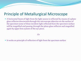
1. The document discusses metallurgical microscopes, including their principles, construction, types of objectives and eyepieces, defects in lenses, and applications in materials analysis.
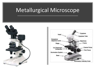
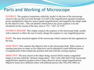
2. Key parts of microscopes are described like the eyepiece, objective, stage, illumination and various types of objectives and eyepieces.
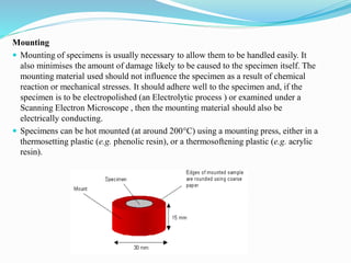
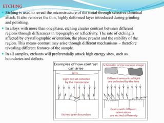
3. Sample preparation techniques for microscopy like sectioning, grinding, polishing and etching are outlined to reveal microstructural features for analysis.