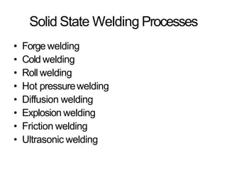
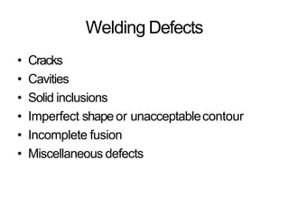
Advanced Welding Technology
By Lalit Yadav
Asst.Prof.(Mech.Engg.)
Introduction
• Welding is a process of joining two metal pieces by the
application of heat. Welding is the least expensive process and
widely used now a days in fabrication. Welding joints different
metals with the help of a number of processes in which heat is
supplied either electrically or by mean of a gas torch. Different
welding processes are used in the manufacturing of Auto
mobiles bodies, structural work, tanks, and general machine
repair work. In the industries , welding is used in refineries and
pipe line fabrication. It may be called a secondary
manufacturing process.
Modern welding technology started just before the end of 19th
century with the development of methods for generating high
temperature in localized zones to melt the material.
•
WELDINGPROCESSES
1. Arc Welding
2. Resistance Welding
3. Oxyfuel GasWelding
4. Other Fusion Welding Processes
5. Solid State Welding
6. Weld Quality
7. Weldability
8. Design Considerations in Welding
TwoCategoriesof Welding Processes
• Fusion welding - coalescence is accomplished
by melting the two parts to be joined, in some
casesadding filler metal to thejoint
– Examples: arc welding, resistance spot welding,
oxyfuel gaswelding.
• Solidstate welding- heat and/or pressureare
used to achieve coalescence, but no melting
of basemetals occurs and no filler metal is
added
– Examples: forge welding, diffusion welding,
friction welding.
ArcWelding (AW)
Afusion welding process in which coalescence
of the metals is achieved by the heat from an
electric arc between an electrode and the
work
• Electric energy from the arc produces
temperatures ~10,000 F(5500 C),hot enough
to melt anymetal
• Most AWprocessesadd filler metal to
increase volume and strength of weldjoint.
What is an Electric Arc?
An electric arc is adischarge of electriccurrent
acrossagapin acircuit
• It is sustained by an ionized column ofgas
(plasma) through which the currentflows
• Toinitiate the arc in AW,electrode isbrought
into contact with work and then quickly
separated from it by ashortdistance
Arc Welding
• Apool of molten metal is formed near
electrode tip, and aselectrode is moved
along joint, molten weld poolsolidifies in
its wake
Manual ArcWelding andArc Time
• Problems with manualwelding:
– Weld joint quality
– Productivity
• Arc Time =(time arc is on) dividedby
(hours worked)
– Also called “arc-on time”
– Manual welding arc time =20%
– Machine welding arc time ~50%
Two BasicTypesof AWElectrodes
• Consumable– consumed during welding
process
– Sourceof filler metal inarc welding
• Nonconsumable– not consumedduring
welding process
– Filler metal must be added separately if itis
added
ConsumableElectrodes
• Formsof consumableelectrodes
– Welding rods are 9 to 18 inches and 3/8 inch orlessin
diameter and must be changedfrequently
– Weld wire can be continuously fed from spools with long
lengths of wire, avoiding frequentinterruptions
In both rod and wire forms, electrode is consumed by the arc
and added to weld joint asfillermetal
•
NonconsumableElectrodes
•
•
Made of tungsten which resistsmelting
Gradually depleted during welding (vaporizationis
principal mechanism)
Any filler metal must be supplied by aseparate wirefed
into weldpool
•
ArcShielding
• At high temperatures in AW,metals arechemically
reactive to oxygen, nitrogen, and hydrogen inair
– Mechanical properties of joint can be degraded bythese
reactions
– Toprotect operation, arc must be shieldedfrom
surrounding air in AWprocesses
Arc shielding is accomplishedby:
–Shielding gases,e.g., argon, helium, CO2
– Flux
(In high-temperature metal joining processes (welding,
brazing and soldering), the primary purpose of fluxis to
prevent oxidation of the baseand filler materials. Tin-lead
solder (e.g.) attaches very well to copper, but poorly to the
various oxides of copper, which form quickly at soldering
temperatures.)
•
Power Sourcein ArcWelding
• Direct current (DC)vs.Alternating current (AC)
– ACmachines lessexpensive to purchase and
operate, but generally restricted toferrous metals
– DCequipment can be used on all metals and is
generally noted for better arccontrol
Consumable Electrode
AWProcesses
• Shielded Metal Arc Welding(SMAW)
• GasMetal Arc Welding(GMAW)
• Flux-CoredArc Welding (FCAW)
• Electrogas Welding (EGW)
• SubmergedArc Welding (SAW)
Shielded Metal Arc Welding (SMAW)
Welding Stick in SMAW
• Composition of fillermetal ( aluminum ,tin
or lead)usually close to basemetal
• Coating: powdered cellulose mixed with
oxides and carbonates, and held togetherby
asilicate binder
• Welding stick is clamped in electrodeholder
connected to powersource
• Disadvantages of stickwelding:
– Sticksmust be periodically changed
– High current levels may melt coatingprematurely
SMAWApplications
• Usedfor steels, stainless steels,cast
irons, and certain nonferrousalloys
• Not used or rarely used for
aluminum and its alloys,copper
alloys, and titanium
GasMetal ArcWelding(GMAW)
Usesaconsumable bare metal wire aselectrode
with shielding by flooding arc withagas
• Wire is fed continuously andautomatically
from aspool through the weldinggun
• Shielding gasesinclude argon and helium for
aluminum welding, and CO2
for steelwelding
• Bare electrode wire plus shieldinggases
eliminate slagon weld bead
– No need for manual grinding and cleaning ofslag
Gas Metal Arc Welding
GMAWAdvantages over SMAW
• Better arc time becauseof continuouswire
electrode
– Sticksmust be periodically changed in SMAW
• Better useof electrode filler metalthan
SMAW
– Endof stick cannot be usedinSMAW
• Higher deposition rates
• Eliminates problem of slagremoval
• Canbe readily automated
Flux-CoredArcWelding (FCAW)
Adaptation of shielded metal arc welding, to
overcome limitations of stick electrodes -two
versions
– Self-shielded FCAW- core includes compounds that
produce shielding gases
– Gas-shielded FCAW- usesexternally applied shielding
gases
• Electrode is a continuous consumable tubing (in
coils) containing flux and other ingredients (e.g.,
alloying elements) in itscore
Flux-Cored Arc Welding
Presenceor absenceof externally supplied shielding gas
distinguishes: (1) self-shielded - core provides ingredientsfor
shielding, (2) gas-shielded - usesexternal shieldinggases
ElectrogasWelding (EGW)
Usesacontinuous consumable electrode,
flux-cored wire or bare wire with externally
supplied shielding gases,and molding shoesto
contain molten metal.
• When flux-cored electrode wire is used and no
external gasesare supplied, then special caseof
self-shielded FCAW
• When a bare electrode wire used with shielding
gases from external source, then special caseof
GMAW
• Electrogas welding using flux-cored electrode wire: (a) front view
with molding shoe removed for clarity, and (b) side view showing
molding shoeson both sides
Electrogas Welding
SubmergedArcWelding (SAW)
Uses a continuous, consumable bare wire
electrode, with arc shielding by a cover of
granular flux
• Electrode wire is fed automatically froma
coil
• Flux introduced into joint slightlyahead
of arc by gravity from ahopper
– Completely submerges operation, preventing
sparks, spatter, andradiation
Submerged Arc Welding
SAWApplications andProducts
• Steel fabrication of structural shapes(e.g.,
I-beams)
• Seamsfor large diameter pipes, tanks,and
pressure vessels
• Welded components for heavymachinery
• Most steels (except hi Csteel)
• Not good for nonferrousmetals
NonconsumableElectrode
Processes
• GasTungstenArc Welding
• PlasmaArc Welding
• CarbonArc Welding
• Stud Welding
GasTungsten Arc Welding (GTAW)
Usesanon-consumable tungsten electrode
and an inert gasfor arcshielding
• Melting point of tungsten =3410C(6170F)
• A.k.a.Tungsten Inert Gas(TIG)welding
– In Europe, called "WIGwelding"
• Usedwith or without afillermetal
– When filler metal used, it is added to weld pool from
separate rod or wire
• Applications: aluminum and stainlesssteel
mostly
Gas Tungsten Arc Welding
AdvantagesandDisadvantagesof
GTAW
Advantages:
•
•
•
High quality welds for suitable applications
No spatter becauseno filler metal througharc
Little or no post-weld cleaning because noflux
Disadvantages:
• Generally slower and more costly thanconsumable
electrode AWprocesses
PlasmaArcWelding (PAW)
Specialform of GTAWin which aconstricted
plasma arc is directed at weldarea
• Tungsten electrode is contained in anozzle
that focuses ahigh velocity stream of inert gas
(argon) into arc region toform ahigh velocity,
intensely hot plasma arcstream
• Temperatures in PAWreach 28,000C
(50,000F), due to constriction of arc,
producing aplasma jet of small diameterand
very high energydensity
Plasma Arc Welding
AdvantagesandDisadvantagesof
PAW
Advantages:
• Good arc stability and excellent weldquality
• Better penetration control than otherAW
processes
• High travel speeds
•Canbe used to weld almost anymetals
Disadvantages:
• High equipment cost
• Larger torch sizethan other AWprocesses
– Tendsto restrict accessin somejoints
ResistanceWelding (RW)
Agroup of fusion welding processesthat usea
combination of heat and pressure to
accomplish coalescence
• Heat generated by electrical resistanceto
current flow at junction to be welded
• Principal RWprocess is resistance spot
welding (RSW)
Resistance Welding
• Resistance welding,
showing
components in spot
welding, the main
process in the RW
group
Componentsin ResistanceSpot
Welding
• Parts to be welded (usually sheetmetal)
• Two opposing electrodes
• Means of applying pressure tosqueezeparts
between electrodes
• Power supply from which acontrolledcurrent
canbe applied for aspecified time duration
AdvantagesandDrawbacksof
ResistanceWelding
Advantages:
• No filler metalrequired
• High production rates possible
• Lendsitself to mechanization andautomation
• Lower operator skill level than forarc welding
•Goodrepeatability andreliability
Disadvantages:
• High initial equipment cost
• Limited to lap joints formost RWprocesses
ResistanceSpotWelding (RSW)
Resistance welding process in which fusionof
faying surfaces of alap joint is achieved at
one location by opposingelectrodes
• Usedto join sheet metalparts
• Widely used in massproduction of
automobiles, metal furniture, appliances,and
other sheet metalproducts
– Typical car body has~10,000 spot welds
– Annual production of automobiles in the world is
measured in tens of millions of units
(a) Spot welding cycle
(b)Plot of forceand
current
Cycle:
(1)parts inserted
between electrodes,
(2) electrodes close,
(3) current on,
(4) current off,
(5)electrodes
opened
Spot Welding Cycle
ResistanceSeamWelding (RSEW)
Usesrotating wheel electrodes to producea
series of overlapping spot welds along lap
joint
• Canproduce air-tight joints
• Applications:
– Gasoline tanks
– Automobile mufflers
– Various sheet metal containers
Resistance Seam Welding
ResistanceProjectionWelding (RPW)
Aresistance welding process in which coalescence occurs at one
or more small contact points on the parts
Contact points determined by design of parts tobe joined
– May consist of projections, embossments, or localized
intersections of parts
•
(1) Start of operation, contact between parts is at projections;
(2)When current is applied, weld nuggets similar tospot
welding are formed at theprojections
Resistance Projection Welding
Other ResistanceProjection Welding Operations
(a) Welding of fastener on sheetmetal
(b) cross-wire welding
Oxy-fuel GasWelding(OFW)
Group of fusion welding operations thatburn
various fuels mixed with oxygen
• OFWemploys several types of gases,which is the
primary distinction among the members of this
group
• Oxyfuel gasis also used in flame cutting torches
tocut and separate metal plates and other parts
• Most important OFWprocess is oxyacetylene
welding
OxyacetyleneWelding (OAW)
Fusion welding performed by ahigh temperature flame from
combustion of acetylene andoxygen
Flame is directed by awelding torch
Filler metal is sometimesadded
– Composition must be similar to basemetal
– Filler rod often coated with flux to clean surfaces and
prevent oxidation
•
•
Oxyacetylene Welding
Acetylene (C2H2)
• Most popular fuel among OFWgroupbecause
it is capable of higher temperatures than any
other
– Up to 3480C(6300F)
• Two stage reaction of acetylene andoxygen:
– First stage reaction (inner cone offlame)
C2
H2
+O2 2CO+H2+heat
– Secondstage reaction (outer envelope)
2CO+H2+1.5O2 2CO2+H2
O+heat
• Maximum temperature reached at tip of inner cone, while
outer envelope spreads out and shields work surface from
atmosphere
Shown below is neutral flame of oxyacetylene torch indicating
temperatures achieved
•
Oxyacetylene Torch
Safety Issuein OAW
• Together, acetylene and oxygen arehighly
flammable
• C2
H2
is colorless and odorless
– It is therefore processed to have characteristicgarlic
odor
OAWSafety Issue
• C2
H2
is physically unstable at pressuresmuch
above 15 lb/in2 (about 1atm)
– Storage cylinders are packed with porous fillermaterial
saturated with acetone(CH3
COCH3
)
– Acetone dissolves about 25 times its ownvolume of
acetylene
• Different screw threads are standard on C2
H2
and O2cylinders and hosesto avoidaccidental
connection of wronggases
Alternative Gasesfor OFW
• Methylacetylene-Propadiene (MAPP)
• Hydrogen
• Propylene
• Propane
• Natural Gas
Other Fusion Welding Processes
FWprocessesthat cannot be classified asarc,
resistance, or oxyfuelwelding
• Useunique technologies to develop heatfor
melting
• Applications are typically unique
• Processesinclude:
– Electron beam welding
– Laserbeam welding
– Electroslag welding
– Thermit welding
Electron BeamWelding (EBW)
Fusion welding process in which heat for
welding is provided by ahighly-focused,
high-intensity stream of electronsstriking
work surface
• Electron beam gun operatesat:
– High voltage (e.g., 10 to 150 kVtypical) toaccelerate
electrons
– Beamcurrents are low (measured inmilliamps)
• Power in EBWnotexceptional.
Electron BeamWelding (EBW)
EBWVacuumChamber
• When first developed, EBWhad to becarried
out in avacuum chamber to minimize
disruption of electron beam by airmolecules
– Serious inconvenience in production
• Pumpdown time can take aslong asan hour
Three Vacuum Levelsin EBW
1. High-vacuum welding – welding in same vacuum
chamber as beam generation to produce highest
quality weld
2. Medium-vacuum welding – welding in separate
chamber but partial vacuum reducespump-down
time
3. Non-vacuum welding – welding done at or near
atmospheric pressure, with work positionedclose to
electron beam generator - requires vacuum divider
to separate work from beamgenerator
AdvantagesandDisadvantagesof EBW
Advantages:
• High-quality welds, deep and narrowprofiles
• Limited heat affected zone, lowthermal
distortion
•No flux or shielding gasesneeded
Disadvantages:
• High equipment cost
• Precisejoint preparation & alignmentrequired
• Vacuum chamber required
• Safety concern: EBWgeneratesx-rays
LaserBeamWelding (LBW)
Fusion welding process in which coalescenceis
achieved by energy of ahighly concentrated,
coherent light beam focused onjoint.
• LBWnormally performed with shieldinggases
to preventoxidation
• Filler metal not usuallyadded
• High power density in smallarea
– SoLBWoften used for small parts
Comparison: LBWvs. EBW
• No vacuum chamber required for LBW
• No x-rays emitted in LBW
• Laserbeams canbe focused and directed by
optical lensesandmirrors
• LBWnot capable of the deep welds andhigh
depth-to-width ratios ofEBW
– Maximum LBWdepth =~19 mm (3/4 in), whereas
EBWdepths =50 mm (2in)
Thermit Welding (TW)
FWprocess in which heat for coalescenceis
produced by superheated molten metal fromthe
chemical reaction of thermite
• Thermite = mixture of Al and Fe3
O4finepowders
that produce an exothermic reaction when
ignited
• Also used for incendiarybombs
• Filler metal obtained from liquidmetal
• Processused for joining, but hasmorein
common with casting thanwelding
• (1) Thermit ignited; (2) crucible tapped, superheated metalflows
into mold; (3) metal solidifies to produce weld joint
Thermit Welding
TWApplications
• Joining of railroadrails
• Repair of cracksin large steel castingsand
forgings
• Weld surface is often smooth enough thatno
finishing is required
SolidState Welding (SSW)
• Coalescenceof part surfaces is achievedby:
– Pressure alone, or
– Heat and pressure
• If both heat and pressure are used, heat is not enough
to melt worksurfaces
– For some SSWprocesses, time is also afactor
• No filler metal isadded
• EachSSWprocess hasits own way of creating
abond at the fayingsurfaces
SuccessFactorsinSSW
• Essential factors for asuccessful solid state weld are thatthe
two faying surfaces mustbe:
– Very clean
– In very close physical contact with each other to permit
atomic bonding
SSWAdvantages over FWProcesses
• If no melting, then no heat affected zone, so
metal around joint retains originalproperties
• Many SSWprocessesproduce welded joints that
bond the entire contact interface between two
parts rather than at distinct spots or seams
• SomeSSWprocessescanbe used to bond
dissimilar metals, without concerns about
relative melting points, thermal expansions,and
other problems that arise inFW
Solid State Welding Processes
• Forge welding
• Cold welding
• Roll welding
• Hot pressurewelding
• Diffusion welding
• Explosion welding
• Friction welding
• Ultrasonic welding
Forge Welding
Welding processin which components tobe joined are
heated to hot working temperature range and then
forged together by hammering or similarmeans
•
• Historic significance in development ofmanufacturing
technology
– Processdates from about 1000 B.C.,when blacksmiths learned to
weld two pieces ofmetal
Of minor commercial importance today except forits
variants
Cold Welding (CW)
SSWprocess done by applying high pressure
between clean contacting surfaces at room
temperature
• Cleaning usually done by degreasing andwire
brushing immediately beforejoining
• No heat is applied, but deformation raiseswork
temperature
• At least one of the metals, preferably both, must
be very ductile
– Soft aluminum and copper suited to CW
• Applications: making electrical connections
Roll Welding (ROW)
SSWprocess in which pressure sufficient to
causecoalescenceis applied by meansof rolls,
either with or without external heat
• Variation of either forge welding or cold
welding, depending on whether heatingof
workparts is done prior toprocess
– If no external heat, called coldroll welding
– If heat is supplied, hot rollwelding
Roll Welding
Roll Welding Applications
• Cladding stainless steel tomild or low alloy
steel for corrosionresistance
• Bimetallic strips for measuringtemperature
• "Sandwich" coins for U.Smint
Diffusion Welding(DFW)
SSWprocess usesheat and pressure, usually in acontrolled
atmosphere, with sufficient time for diffusion and
coalescence to occur
•
•
•
•
Temperatures  0.5 Tm
Plastic deformation at surfaces isminimal
Primary coalescence mechanism is solid state diffusion
Limitation: time required fordiffusion can range from
secondsto hours
DFWApplications
• Joining of high-strength and refractorymetals
in aerospaceand nuclearindustries
• Canbe used to join either similarand
dissimilar metals
– For joining dissimilar metals, afiller layer of
different metal is often sandwiched betweenbase
metals to promotediffusion
Explosion Welding (EXW)
SSWprocess in which rapid coalescence of two metallic surfacesis
caused by the energy of adetonatedexplosive
• No fillermetal used,No external heat applied,No diffusion occurs -
time is too short
• Bonding is metallurgical, combined with mechanical interlocking
that results from arippled or wavy interface between the metals
Explosive Welding
• Commonly used to bond two dissimilar metals, e.g., to clad one
metal on top ofabasemetal over large areas
(1) Setup in parallel configuration, and (2) during detonation of the
explosive charge
•
Friction Welding (FRW)
SSWprocess in which coalescenceis achieved by
frictional heat combined with pressure
• When properly carried out, no meltingoccurs at
faying surfaces
• No filler metal, flux, or shieldinggasesnormally
used
• Processyields anarrow HAZ
• Canbe used to join dissimilarmetals
• Widely used commercial process, amenableto
automation and massproduction
• (1) Rotating part, no contact; (2) parts brought into contact to
generate friction heat; (3) rotation stopped and axial pressure
applied; and (4) weldcreated
Friction Welding
Applications and Limitations of Friction
Welding
Applications:
• Shafts and tubular parts
• Industries: automotive, aircraft, farmequipment,
petroleum and naturalgas
Limitations:
• At least one of theparts must be rotational
• Flashmust usually be removed (extraoperation)
• Upsetting reduces the part lengths (whichmust
be taken into consideration in productdesign)
Friction Stir Welding(FSW)
SSWprocess in which arotating tool is fed along a
joint line between two workpieces, generating
friction heat and mechanically stirring themetal
to form the weldseam
• Distinguished from FRWbecauseheat is
generated by aseparate wear-resistant tool
rather than theparts
• Applications: butt joints inlarge aluminum parts
in aerospace, automotive, andshipbuilding
Friction StirWelding
• (1) Rotating tool just before entering work, and (2) partially
completed weld seam
Advantages and Disadvantages of
Friction Stir Welding
• Advantages
– Good mechanical properties of weldjoint
– Avoids toxic fumes, warping, and shieldingissues
– Little distortion orshrinkage
– Good weld appearance
• Disadvantages
– An exit hole is produce when tool iswithdrawn
– Heavyduty clamping of parts isrequired
Ultrasonic Welding (USW)
Two components are held together, and oscillatory
shear stresses of ultrasonic frequency are applied
to interface to causecoalescence
• Oscillatory motion breaks down any surfacefilms
to allow intimate contact and strong
metallurgical bonding betweensurfaces
• Temperatures are well belowTm
• No filler metals, fluxes, or shieldinggases
• Generally limited to lap joints on soft materials
• (a) General setup for alap joint; and(b)
close-up of weldarea
Ultrasonic Welding
USWApplications
• Wire terminations and splicing in
electrical and electronicsindustry
– Eliminates need for soldering
• Assemblyof aluminum sheetmetal
panels
• Welding of tubes tosheets in solar
panels
• Assemblyof small parts inautomotive
industry
Weld Quality
Concerned with obtaining an acceptableweld
joint that is strong and absent ofdefects
• Also concerned with the methods of
inspecting and testing the joint toassureits
quality
• Topics:
•
•
•
Residualstresses and distortion
Welding defects
Inspection and testing methods
Residual Stressesand Distortion
• Rapidheating and cooling in localizedregions
during FWresult in thermal expansion and
contraction that causeresidualstresses
• Thesestresses,in turn, causedistortion and
warpage
• Situation in welding is complicatedbecause:
– Heating is very localized
– Melting of basemetals in theseregions
– Location of heating and melting is in motion (at least in
AW)
Residual Stressesand Distortion
(a)Butt welding
two plates
(b) Shrinkage
(c)Residual
stresspatterns
(d)Likely
warping of
weldment
Techniques to MinimizeWarpage
Welding fixtures to physically restrain parts
Heat sinks to rapidly removeheat
•
•
• Tackwelding at multiple points along joint tocreate arigid
structure prior to seamwelding
Selection of welding conditions (speed, amount offiller
metal used, etc.) to reducewarpage
Preheating baseparts, Stressrelief heat treatment of
welded assembly
•
•
Welding Defects
• Cracks
• Cavities
• Solid inclusions
• Imperfect shape or unacceptablecontour
• Incomplete fusion
• Miscellaneous defects
Welding Cracks
Fracture-type interruptions either in weld orin basemetal
adjacent to weld
•
•
• Serious defect becauseit is adiscontinuity in themetal
that significantly reducesstrength
Causedby embrittlement or low ductility of weld and/or
basemetal combined with high restraint during
contraction
In general, this defect must berepaired
Cavities
Two defect types, similar todefects found in
castings:
1. Porosity - small voids in weld metal formed by gases
entrapped during solidification
– Causedby inclusion of atmospheric gases,sulfurin
weld metal, or surfacecontaminants
1. Shrinkage voids - cavities formed by shrinkageduring
solidification
Solid Inclusions
Nonmetallic material entrapped in weldmetal
•
• Most common form is slaginclusions generated duringAW
processes that useflux
– Instead of floating to top of weld pool, globules of slag
become encased during solidification
Other forms: metallic oxides that form during welding of
certain metals such asaluminum, which normally hasa
surface coating of Al2O3
Incomplete Fusion
Aweld bead in which fusion hasnot occurred
throughout entire crosssection ofjoint
• Several forms of incomplete fusionare
shown below
• (a) Desired profile for single V-groove weldjoint,
(b) undercut - portion of basemetal meltedaway,
(c)underfill - depression in weld below adjacent
basemetal surface, and (d) overlap - weld metal
spills beyond joint onto part surface but no fusion
occurs
Weld Profile in AW
Inspection and TestingMethods
• Visual inspection
• Nondestructive evaluation
• Destructive testing
Visual Inspection
•
•
Most widely used welding inspectionmethod
Human inspector visually examinesfor:
– Conformance to dimensions,wWarpage
– Cracks,cavities, incomplete fusion, and other surface
defects
Limitations:
– Only surface defects are detectable
– Welding inspector must also decide if additional testsare
warranted
•
Nondestructive Evaluation
(NDE)Tests
• Ultrasonic testing - high frequency sound waves
through specimen to detect cracks andinclusions
• Radiographic testing - x-rays or gammaradiation
provide photograph of internalflaws
• Dye-penetrant and fluorescent-penetrant tests -
to detect small cracksand cavities at partsurface
• Magnetic particle testing – iron filings sprinkled
on surface reveal subsurface defects bydistorting
magnetic field in part
Destructive Testing
Tests in which weld is destroyed eitherduring
testing or to prepare testspecimen
• Mechanical tests - purpose is similar to
conventional testing methods suchastensile
tests, shear tests, etc
• Metallurgical tests - preparation of metallurgical
specimens (e.g., photomicrographs) of weldment
to examine metallic structure, defects, extent
and condition of heat affected zone, and similar
phenomena
Mechanical Testsin Welding
• (a) Tension-shear test, (b) fillet break test, (c) tension-shearof
spot weld, and (d) peel test for spot weld
Weldability
Capacity of ametal or combination ofmetals to
be welded into asuitable structure, and for
the resulting weld joint(s) to possessthe
required metallurgical properties to perform
satisfactorily in intendedservice
• Goodweldability characterizedby:
– Easewith which welding isaccomplished
– Absenceof weld defects
– Strength, ductility, and toughness in weldedjoint
Weldability Factors – WeldingProcess
• Somemetals or metal combinations canbe
readily welded by one process but aredifficult
to weld byothers
– Example: stainless steel readily welded by most AWand
RWprocesses, but difficult to weld byOFW
Weldability Factors – BaseMetal
• Somemetals melt too easily; e.g.,aluminum
• Metals with high thermal conductivity
transfer heat away from weld, whichcauses
problems; e.g., copper
• High thermal expansion and contraction in
metal causesdistortion problems
• Dissimilar metals pose problems in welding
when their physical and/or mechanical
properties are substantiallydifferent
Other Factors Affecting Weldability
• Filler metal
– Must be compatible with basemetal(s)
– In general, elements mixed in liquid state that form
asolid solution upon solidification do not causea
problem
• Surfaceconditions
– Moisture can result in porosity in fusion zone
– Oxides and other films on metal surfacescan
prevent adequate contact andfusion
Design Considerations in Welding
• Design for welding - product should be
designed from the start asaweldedassembly
– Not asacasting or forging or other formedshape
• Minimum parts - welded assembliesshould
consist of fewest number ofparts possible
– Example: usually more cost efficient to perform simple
bending operations on a part than to weld an assembly
from flat plates andsheets
Arc Welding DesignGuidelines
• Good fit-up of parts - to maintain
dimensional control and minimize
distortion
– Machining is sometimes required to achieve
satisfactory fit-up
• Assembly must allow accessfor welding
gun to reach weldingarea
• Designof assembly should allow flat
welding to be performed asmuch as
possible, since this is the fastest andmost
convenient welding position
Arc Welding Positions
• Welding positions defined here for
groove welds: (a) flat, (b) horizontal,(c)
vertical, and (d) overhead
Design Guidelines - RSW
• Low-carbon sheet steel up to0.125 (3.2 mm) is
ideal metal for RSW
• How additional strength and stiffness can be
obtained in large flatsheet metal components
– Spot welding reinforcing parts intothem
– Forming flanges and embossments
• Spot welded assembly must provide accessfor
electrodes to reach weldingarea
• Sufficient overlap of sheet metal partsrequired
for electrode tip to make proper contact
AWTS PPT.pptx
AWTS PPT.pptx

AWTS PPT.pptx

  • 1.
    Advanced Welding Technology ByLalit Yadav Asst.Prof.(Mech.Engg.)
  • 2.
    Introduction • Welding isa process of joining two metal pieces by the application of heat. Welding is the least expensive process and widely used now a days in fabrication. Welding joints different metals with the help of a number of processes in which heat is supplied either electrically or by mean of a gas torch. Different welding processes are used in the manufacturing of Auto mobiles bodies, structural work, tanks, and general machine repair work. In the industries , welding is used in refineries and pipe line fabrication. It may be called a secondary manufacturing process. Modern welding technology started just before the end of 19th century with the development of methods for generating high temperature in localized zones to melt the material. •
  • 5.
    WELDINGPROCESSES 1. Arc Welding 2.Resistance Welding 3. Oxyfuel GasWelding 4. Other Fusion Welding Processes 5. Solid State Welding 6. Weld Quality 7. Weldability 8. Design Considerations in Welding
  • 6.
    TwoCategoriesof Welding Processes •Fusion welding - coalescence is accomplished by melting the two parts to be joined, in some casesadding filler metal to thejoint – Examples: arc welding, resistance spot welding, oxyfuel gaswelding. • Solidstate welding- heat and/or pressureare used to achieve coalescence, but no melting of basemetals occurs and no filler metal is added – Examples: forge welding, diffusion welding, friction welding.
  • 7.
    ArcWelding (AW) Afusion weldingprocess in which coalescence of the metals is achieved by the heat from an electric arc between an electrode and the work • Electric energy from the arc produces temperatures ~10,000 F(5500 C),hot enough to melt anymetal • Most AWprocessesadd filler metal to increase volume and strength of weldjoint.
  • 8.
    What is anElectric Arc? An electric arc is adischarge of electriccurrent acrossagapin acircuit • It is sustained by an ionized column ofgas (plasma) through which the currentflows • Toinitiate the arc in AW,electrode isbrought into contact with work and then quickly separated from it by ashortdistance
  • 9.
    Arc Welding • Apoolof molten metal is formed near electrode tip, and aselectrode is moved along joint, molten weld poolsolidifies in its wake
  • 10.
    Manual ArcWelding andArcTime • Problems with manualwelding: – Weld joint quality – Productivity • Arc Time =(time arc is on) dividedby (hours worked) – Also called “arc-on time” – Manual welding arc time =20% – Machine welding arc time ~50%
  • 11.
    Two BasicTypesof AWElectrodes •Consumable– consumed during welding process – Sourceof filler metal inarc welding • Nonconsumable– not consumedduring welding process – Filler metal must be added separately if itis added
  • 12.
    ConsumableElectrodes • Formsof consumableelectrodes –Welding rods are 9 to 18 inches and 3/8 inch orlessin diameter and must be changedfrequently – Weld wire can be continuously fed from spools with long lengths of wire, avoiding frequentinterruptions In both rod and wire forms, electrode is consumed by the arc and added to weld joint asfillermetal •
  • 13.
    NonconsumableElectrodes • • Made of tungstenwhich resistsmelting Gradually depleted during welding (vaporizationis principal mechanism) Any filler metal must be supplied by aseparate wirefed into weldpool •
  • 14.
    ArcShielding • At hightemperatures in AW,metals arechemically reactive to oxygen, nitrogen, and hydrogen inair – Mechanical properties of joint can be degraded bythese reactions – Toprotect operation, arc must be shieldedfrom surrounding air in AWprocesses Arc shielding is accomplishedby: –Shielding gases,e.g., argon, helium, CO2 – Flux (In high-temperature metal joining processes (welding, brazing and soldering), the primary purpose of fluxis to prevent oxidation of the baseand filler materials. Tin-lead solder (e.g.) attaches very well to copper, but poorly to the various oxides of copper, which form quickly at soldering temperatures.) •
  • 15.
    Power Sourcein ArcWelding •Direct current (DC)vs.Alternating current (AC) – ACmachines lessexpensive to purchase and operate, but generally restricted toferrous metals – DCequipment can be used on all metals and is generally noted for better arccontrol
  • 16.
    Consumable Electrode AWProcesses • ShieldedMetal Arc Welding(SMAW) • GasMetal Arc Welding(GMAW) • Flux-CoredArc Welding (FCAW) • Electrogas Welding (EGW) • SubmergedArc Welding (SAW)
  • 17.
    Shielded Metal ArcWelding (SMAW)
  • 18.
    Welding Stick inSMAW • Composition of fillermetal ( aluminum ,tin or lead)usually close to basemetal • Coating: powdered cellulose mixed with oxides and carbonates, and held togetherby asilicate binder • Welding stick is clamped in electrodeholder connected to powersource • Disadvantages of stickwelding: – Sticksmust be periodically changed – High current levels may melt coatingprematurely
  • 19.
    SMAWApplications • Usedfor steels,stainless steels,cast irons, and certain nonferrousalloys • Not used or rarely used for aluminum and its alloys,copper alloys, and titanium
  • 20.
    GasMetal ArcWelding(GMAW) Usesaconsumable baremetal wire aselectrode with shielding by flooding arc withagas • Wire is fed continuously andautomatically from aspool through the weldinggun • Shielding gasesinclude argon and helium for aluminum welding, and CO2 for steelwelding • Bare electrode wire plus shieldinggases eliminate slagon weld bead – No need for manual grinding and cleaning ofslag
  • 21.
  • 22.
    GMAWAdvantages over SMAW •Better arc time becauseof continuouswire electrode – Sticksmust be periodically changed in SMAW • Better useof electrode filler metalthan SMAW – Endof stick cannot be usedinSMAW • Higher deposition rates • Eliminates problem of slagremoval • Canbe readily automated
  • 23.
    Flux-CoredArcWelding (FCAW) Adaptation ofshielded metal arc welding, to overcome limitations of stick electrodes -two versions – Self-shielded FCAW- core includes compounds that produce shielding gases – Gas-shielded FCAW- usesexternally applied shielding gases • Electrode is a continuous consumable tubing (in coils) containing flux and other ingredients (e.g., alloying elements) in itscore
  • 24.
    Flux-Cored Arc Welding Presenceorabsenceof externally supplied shielding gas distinguishes: (1) self-shielded - core provides ingredientsfor shielding, (2) gas-shielded - usesexternal shieldinggases
  • 25.
    ElectrogasWelding (EGW) Usesacontinuous consumableelectrode, flux-cored wire or bare wire with externally supplied shielding gases,and molding shoesto contain molten metal. • When flux-cored electrode wire is used and no external gasesare supplied, then special caseof self-shielded FCAW • When a bare electrode wire used with shielding gases from external source, then special caseof GMAW
  • 26.
    • Electrogas weldingusing flux-cored electrode wire: (a) front view with molding shoe removed for clarity, and (b) side view showing molding shoeson both sides Electrogas Welding
  • 27.
    SubmergedArcWelding (SAW) Uses acontinuous, consumable bare wire electrode, with arc shielding by a cover of granular flux • Electrode wire is fed automatically froma coil • Flux introduced into joint slightlyahead of arc by gravity from ahopper – Completely submerges operation, preventing sparks, spatter, andradiation
  • 28.
  • 29.
    SAWApplications andProducts • Steelfabrication of structural shapes(e.g., I-beams) • Seamsfor large diameter pipes, tanks,and pressure vessels • Welded components for heavymachinery • Most steels (except hi Csteel) • Not good for nonferrousmetals
  • 30.
    NonconsumableElectrode Processes • GasTungstenArc Welding •PlasmaArc Welding • CarbonArc Welding • Stud Welding
  • 31.
    GasTungsten Arc Welding(GTAW) Usesanon-consumable tungsten electrode and an inert gasfor arcshielding • Melting point of tungsten =3410C(6170F) • A.k.a.Tungsten Inert Gas(TIG)welding – In Europe, called "WIGwelding" • Usedwith or without afillermetal – When filler metal used, it is added to weld pool from separate rod or wire • Applications: aluminum and stainlesssteel mostly
  • 32.
  • 33.
    AdvantagesandDisadvantagesof GTAW Advantages: • • • High quality weldsfor suitable applications No spatter becauseno filler metal througharc Little or no post-weld cleaning because noflux Disadvantages: • Generally slower and more costly thanconsumable electrode AWprocesses
  • 34.
    PlasmaArcWelding (PAW) Specialform ofGTAWin which aconstricted plasma arc is directed at weldarea • Tungsten electrode is contained in anozzle that focuses ahigh velocity stream of inert gas (argon) into arc region toform ahigh velocity, intensely hot plasma arcstream • Temperatures in PAWreach 28,000C (50,000F), due to constriction of arc, producing aplasma jet of small diameterand very high energydensity
  • 35.
  • 36.
    AdvantagesandDisadvantagesof PAW Advantages: • Good arcstability and excellent weldquality • Better penetration control than otherAW processes • High travel speeds •Canbe used to weld almost anymetals Disadvantages: • High equipment cost • Larger torch sizethan other AWprocesses – Tendsto restrict accessin somejoints
  • 37.
    ResistanceWelding (RW) Agroup offusion welding processesthat usea combination of heat and pressure to accomplish coalescence • Heat generated by electrical resistanceto current flow at junction to be welded • Principal RWprocess is resistance spot welding (RSW)
  • 38.
    Resistance Welding • Resistancewelding, showing components in spot welding, the main process in the RW group
  • 39.
    Componentsin ResistanceSpot Welding • Partsto be welded (usually sheetmetal) • Two opposing electrodes • Means of applying pressure tosqueezeparts between electrodes • Power supply from which acontrolledcurrent canbe applied for aspecified time duration
  • 40.
    AdvantagesandDrawbacksof ResistanceWelding Advantages: • No fillermetalrequired • High production rates possible • Lendsitself to mechanization andautomation • Lower operator skill level than forarc welding •Goodrepeatability andreliability Disadvantages: • High initial equipment cost • Limited to lap joints formost RWprocesses
  • 41.
    ResistanceSpotWelding (RSW) Resistance weldingprocess in which fusionof faying surfaces of alap joint is achieved at one location by opposingelectrodes • Usedto join sheet metalparts • Widely used in massproduction of automobiles, metal furniture, appliances,and other sheet metalproducts – Typical car body has~10,000 spot welds – Annual production of automobiles in the world is measured in tens of millions of units
  • 42.
    (a) Spot weldingcycle (b)Plot of forceand current Cycle: (1)parts inserted between electrodes, (2) electrodes close, (3) current on, (4) current off, (5)electrodes opened Spot Welding Cycle
  • 43.
    ResistanceSeamWelding (RSEW) Usesrotating wheelelectrodes to producea series of overlapping spot welds along lap joint • Canproduce air-tight joints • Applications: – Gasoline tanks – Automobile mufflers – Various sheet metal containers
  • 44.
  • 45.
    ResistanceProjectionWelding (RPW) Aresistance weldingprocess in which coalescence occurs at one or more small contact points on the parts Contact points determined by design of parts tobe joined – May consist of projections, embossments, or localized intersections of parts •
  • 46.
    (1) Start ofoperation, contact between parts is at projections; (2)When current is applied, weld nuggets similar tospot welding are formed at theprojections Resistance Projection Welding
  • 47.
    Other ResistanceProjection WeldingOperations (a) Welding of fastener on sheetmetal (b) cross-wire welding
  • 48.
    Oxy-fuel GasWelding(OFW) Group offusion welding operations thatburn various fuels mixed with oxygen • OFWemploys several types of gases,which is the primary distinction among the members of this group • Oxyfuel gasis also used in flame cutting torches tocut and separate metal plates and other parts • Most important OFWprocess is oxyacetylene welding
  • 49.
    OxyacetyleneWelding (OAW) Fusion weldingperformed by ahigh temperature flame from combustion of acetylene andoxygen Flame is directed by awelding torch Filler metal is sometimesadded – Composition must be similar to basemetal – Filler rod often coated with flux to clean surfaces and prevent oxidation • •
  • 50.
  • 51.
    Acetylene (C2H2) • Mostpopular fuel among OFWgroupbecause it is capable of higher temperatures than any other – Up to 3480C(6300F) • Two stage reaction of acetylene andoxygen: – First stage reaction (inner cone offlame) C2 H2 +O2 2CO+H2+heat – Secondstage reaction (outer envelope) 2CO+H2+1.5O2 2CO2+H2 O+heat
  • 52.
    • Maximum temperaturereached at tip of inner cone, while outer envelope spreads out and shields work surface from atmosphere Shown below is neutral flame of oxyacetylene torch indicating temperatures achieved • Oxyacetylene Torch
  • 53.
    Safety Issuein OAW •Together, acetylene and oxygen arehighly flammable • C2 H2 is colorless and odorless – It is therefore processed to have characteristicgarlic odor
  • 54.
    OAWSafety Issue • C2 H2 isphysically unstable at pressuresmuch above 15 lb/in2 (about 1atm) – Storage cylinders are packed with porous fillermaterial saturated with acetone(CH3 COCH3 ) – Acetone dissolves about 25 times its ownvolume of acetylene • Different screw threads are standard on C2 H2 and O2cylinders and hosesto avoidaccidental connection of wronggases
  • 55.
    Alternative Gasesfor OFW •Methylacetylene-Propadiene (MAPP) • Hydrogen • Propylene • Propane • Natural Gas
  • 56.
    Other Fusion WeldingProcesses FWprocessesthat cannot be classified asarc, resistance, or oxyfuelwelding • Useunique technologies to develop heatfor melting • Applications are typically unique • Processesinclude: – Electron beam welding – Laserbeam welding – Electroslag welding – Thermit welding
  • 57.
    Electron BeamWelding (EBW) Fusionwelding process in which heat for welding is provided by ahighly-focused, high-intensity stream of electronsstriking work surface • Electron beam gun operatesat: – High voltage (e.g., 10 to 150 kVtypical) toaccelerate electrons – Beamcurrents are low (measured inmilliamps) • Power in EBWnotexceptional.
  • 58.
  • 59.
    EBWVacuumChamber • When firstdeveloped, EBWhad to becarried out in avacuum chamber to minimize disruption of electron beam by airmolecules – Serious inconvenience in production • Pumpdown time can take aslong asan hour
  • 60.
    Three Vacuum LevelsinEBW 1. High-vacuum welding – welding in same vacuum chamber as beam generation to produce highest quality weld 2. Medium-vacuum welding – welding in separate chamber but partial vacuum reducespump-down time 3. Non-vacuum welding – welding done at or near atmospheric pressure, with work positionedclose to electron beam generator - requires vacuum divider to separate work from beamgenerator
  • 61.
    AdvantagesandDisadvantagesof EBW Advantages: • High-qualitywelds, deep and narrowprofiles • Limited heat affected zone, lowthermal distortion •No flux or shielding gasesneeded Disadvantages: • High equipment cost • Precisejoint preparation & alignmentrequired • Vacuum chamber required • Safety concern: EBWgeneratesx-rays
  • 62.
    LaserBeamWelding (LBW) Fusion weldingprocess in which coalescenceis achieved by energy of ahighly concentrated, coherent light beam focused onjoint. • LBWnormally performed with shieldinggases to preventoxidation • Filler metal not usuallyadded • High power density in smallarea – SoLBWoften used for small parts
  • 64.
    Comparison: LBWvs. EBW •No vacuum chamber required for LBW • No x-rays emitted in LBW • Laserbeams canbe focused and directed by optical lensesandmirrors • LBWnot capable of the deep welds andhigh depth-to-width ratios ofEBW – Maximum LBWdepth =~19 mm (3/4 in), whereas EBWdepths =50 mm (2in)
  • 65.
    Thermit Welding (TW) FWprocessin which heat for coalescenceis produced by superheated molten metal fromthe chemical reaction of thermite • Thermite = mixture of Al and Fe3 O4finepowders that produce an exothermic reaction when ignited • Also used for incendiarybombs • Filler metal obtained from liquidmetal • Processused for joining, but hasmorein common with casting thanwelding
  • 66.
    • (1) Thermitignited; (2) crucible tapped, superheated metalflows into mold; (3) metal solidifies to produce weld joint Thermit Welding
  • 67.
    TWApplications • Joining ofrailroadrails • Repair of cracksin large steel castingsand forgings • Weld surface is often smooth enough thatno finishing is required
  • 68.
    SolidState Welding (SSW) •Coalescenceof part surfaces is achievedby: – Pressure alone, or – Heat and pressure • If both heat and pressure are used, heat is not enough to melt worksurfaces – For some SSWprocesses, time is also afactor • No filler metal isadded • EachSSWprocess hasits own way of creating abond at the fayingsurfaces
  • 69.
    SuccessFactorsinSSW • Essential factorsfor asuccessful solid state weld are thatthe two faying surfaces mustbe: – Very clean – In very close physical contact with each other to permit atomic bonding
  • 70.
    SSWAdvantages over FWProcesses •If no melting, then no heat affected zone, so metal around joint retains originalproperties • Many SSWprocessesproduce welded joints that bond the entire contact interface between two parts rather than at distinct spots or seams • SomeSSWprocessescanbe used to bond dissimilar metals, without concerns about relative melting points, thermal expansions,and other problems that arise inFW
  • 71.
    Solid State WeldingProcesses • Forge welding • Cold welding • Roll welding • Hot pressurewelding • Diffusion welding • Explosion welding • Friction welding • Ultrasonic welding
  • 72.
    Forge Welding Welding processinwhich components tobe joined are heated to hot working temperature range and then forged together by hammering or similarmeans • • Historic significance in development ofmanufacturing technology – Processdates from about 1000 B.C.,when blacksmiths learned to weld two pieces ofmetal Of minor commercial importance today except forits variants
  • 73.
    Cold Welding (CW) SSWprocessdone by applying high pressure between clean contacting surfaces at room temperature • Cleaning usually done by degreasing andwire brushing immediately beforejoining • No heat is applied, but deformation raiseswork temperature • At least one of the metals, preferably both, must be very ductile – Soft aluminum and copper suited to CW • Applications: making electrical connections
  • 74.
    Roll Welding (ROW) SSWprocessin which pressure sufficient to causecoalescenceis applied by meansof rolls, either with or without external heat • Variation of either forge welding or cold welding, depending on whether heatingof workparts is done prior toprocess – If no external heat, called coldroll welding – If heat is supplied, hot rollwelding
  • 75.
  • 76.
    Roll Welding Applications •Cladding stainless steel tomild or low alloy steel for corrosionresistance • Bimetallic strips for measuringtemperature • "Sandwich" coins for U.Smint
  • 77.
    Diffusion Welding(DFW) SSWprocess usesheatand pressure, usually in acontrolled atmosphere, with sufficient time for diffusion and coalescence to occur • • • • Temperatures  0.5 Tm Plastic deformation at surfaces isminimal Primary coalescence mechanism is solid state diffusion Limitation: time required fordiffusion can range from secondsto hours
  • 78.
    DFWApplications • Joining ofhigh-strength and refractorymetals in aerospaceand nuclearindustries • Canbe used to join either similarand dissimilar metals – For joining dissimilar metals, afiller layer of different metal is often sandwiched betweenbase metals to promotediffusion
  • 79.
    Explosion Welding (EXW) SSWprocessin which rapid coalescence of two metallic surfacesis caused by the energy of adetonatedexplosive • No fillermetal used,No external heat applied,No diffusion occurs - time is too short • Bonding is metallurgical, combined with mechanical interlocking that results from arippled or wavy interface between the metals
  • 80.
    Explosive Welding • Commonlyused to bond two dissimilar metals, e.g., to clad one metal on top ofabasemetal over large areas (1) Setup in parallel configuration, and (2) during detonation of the explosive charge •
  • 81.
    Friction Welding (FRW) SSWprocessin which coalescenceis achieved by frictional heat combined with pressure • When properly carried out, no meltingoccurs at faying surfaces • No filler metal, flux, or shieldinggasesnormally used • Processyields anarrow HAZ • Canbe used to join dissimilarmetals • Widely used commercial process, amenableto automation and massproduction
  • 82.
    • (1) Rotatingpart, no contact; (2) parts brought into contact to generate friction heat; (3) rotation stopped and axial pressure applied; and (4) weldcreated Friction Welding
  • 83.
    Applications and Limitationsof Friction Welding Applications: • Shafts and tubular parts • Industries: automotive, aircraft, farmequipment, petroleum and naturalgas Limitations: • At least one of theparts must be rotational • Flashmust usually be removed (extraoperation) • Upsetting reduces the part lengths (whichmust be taken into consideration in productdesign)
  • 84.
    Friction Stir Welding(FSW) SSWprocessin which arotating tool is fed along a joint line between two workpieces, generating friction heat and mechanically stirring themetal to form the weldseam • Distinguished from FRWbecauseheat is generated by aseparate wear-resistant tool rather than theparts • Applications: butt joints inlarge aluminum parts in aerospace, automotive, andshipbuilding
  • 85.
    Friction StirWelding • (1)Rotating tool just before entering work, and (2) partially completed weld seam
  • 86.
    Advantages and Disadvantagesof Friction Stir Welding • Advantages – Good mechanical properties of weldjoint – Avoids toxic fumes, warping, and shieldingissues – Little distortion orshrinkage – Good weld appearance • Disadvantages – An exit hole is produce when tool iswithdrawn – Heavyduty clamping of parts isrequired
  • 87.
    Ultrasonic Welding (USW) Twocomponents are held together, and oscillatory shear stresses of ultrasonic frequency are applied to interface to causecoalescence • Oscillatory motion breaks down any surfacefilms to allow intimate contact and strong metallurgical bonding betweensurfaces • Temperatures are well belowTm • No filler metals, fluxes, or shieldinggases • Generally limited to lap joints on soft materials
  • 88.
    • (a) Generalsetup for alap joint; and(b) close-up of weldarea Ultrasonic Welding
  • 89.
    USWApplications • Wire terminationsand splicing in electrical and electronicsindustry – Eliminates need for soldering • Assemblyof aluminum sheetmetal panels • Welding of tubes tosheets in solar panels • Assemblyof small parts inautomotive industry
  • 90.
    Weld Quality Concerned withobtaining an acceptableweld joint that is strong and absent ofdefects • Also concerned with the methods of inspecting and testing the joint toassureits quality • Topics: • • • Residualstresses and distortion Welding defects Inspection and testing methods
  • 91.
    Residual Stressesand Distortion •Rapidheating and cooling in localizedregions during FWresult in thermal expansion and contraction that causeresidualstresses • Thesestresses,in turn, causedistortion and warpage • Situation in welding is complicatedbecause: – Heating is very localized – Melting of basemetals in theseregions – Location of heating and melting is in motion (at least in AW)
  • 92.
    Residual Stressesand Distortion (a)Buttwelding two plates (b) Shrinkage (c)Residual stresspatterns (d)Likely warping of weldment
  • 93.
    Techniques to MinimizeWarpage Weldingfixtures to physically restrain parts Heat sinks to rapidly removeheat • • • Tackwelding at multiple points along joint tocreate arigid structure prior to seamwelding Selection of welding conditions (speed, amount offiller metal used, etc.) to reducewarpage Preheating baseparts, Stressrelief heat treatment of welded assembly • •
  • 94.
    Welding Defects • Cracks •Cavities • Solid inclusions • Imperfect shape or unacceptablecontour • Incomplete fusion • Miscellaneous defects
  • 95.
    Welding Cracks Fracture-type interruptionseither in weld orin basemetal adjacent to weld • • • Serious defect becauseit is adiscontinuity in themetal that significantly reducesstrength Causedby embrittlement or low ductility of weld and/or basemetal combined with high restraint during contraction In general, this defect must berepaired
  • 96.
    Cavities Two defect types,similar todefects found in castings: 1. Porosity - small voids in weld metal formed by gases entrapped during solidification – Causedby inclusion of atmospheric gases,sulfurin weld metal, or surfacecontaminants 1. Shrinkage voids - cavities formed by shrinkageduring solidification
  • 97.
    Solid Inclusions Nonmetallic materialentrapped in weldmetal • • Most common form is slaginclusions generated duringAW processes that useflux – Instead of floating to top of weld pool, globules of slag become encased during solidification Other forms: metallic oxides that form during welding of certain metals such asaluminum, which normally hasa surface coating of Al2O3
  • 98.
    Incomplete Fusion Aweld beadin which fusion hasnot occurred throughout entire crosssection ofjoint • Several forms of incomplete fusionare shown below
  • 99.
    • (a) Desiredprofile for single V-groove weldjoint, (b) undercut - portion of basemetal meltedaway, (c)underfill - depression in weld below adjacent basemetal surface, and (d) overlap - weld metal spills beyond joint onto part surface but no fusion occurs Weld Profile in AW
  • 100.
    Inspection and TestingMethods •Visual inspection • Nondestructive evaluation • Destructive testing
  • 101.
    Visual Inspection • • Most widelyused welding inspectionmethod Human inspector visually examinesfor: – Conformance to dimensions,wWarpage – Cracks,cavities, incomplete fusion, and other surface defects Limitations: – Only surface defects are detectable – Welding inspector must also decide if additional testsare warranted •
  • 103.
    Nondestructive Evaluation (NDE)Tests • Ultrasonictesting - high frequency sound waves through specimen to detect cracks andinclusions • Radiographic testing - x-rays or gammaradiation provide photograph of internalflaws • Dye-penetrant and fluorescent-penetrant tests - to detect small cracksand cavities at partsurface • Magnetic particle testing – iron filings sprinkled on surface reveal subsurface defects bydistorting magnetic field in part
  • 104.
    Destructive Testing Tests inwhich weld is destroyed eitherduring testing or to prepare testspecimen • Mechanical tests - purpose is similar to conventional testing methods suchastensile tests, shear tests, etc • Metallurgical tests - preparation of metallurgical specimens (e.g., photomicrographs) of weldment to examine metallic structure, defects, extent and condition of heat affected zone, and similar phenomena
  • 105.
    Mechanical Testsin Welding •(a) Tension-shear test, (b) fillet break test, (c) tension-shearof spot weld, and (d) peel test for spot weld
  • 106.
    Weldability Capacity of ametalor combination ofmetals to be welded into asuitable structure, and for the resulting weld joint(s) to possessthe required metallurgical properties to perform satisfactorily in intendedservice • Goodweldability characterizedby: – Easewith which welding isaccomplished – Absenceof weld defects – Strength, ductility, and toughness in weldedjoint
  • 107.
    Weldability Factors –WeldingProcess • Somemetals or metal combinations canbe readily welded by one process but aredifficult to weld byothers – Example: stainless steel readily welded by most AWand RWprocesses, but difficult to weld byOFW
  • 108.
    Weldability Factors –BaseMetal • Somemetals melt too easily; e.g.,aluminum • Metals with high thermal conductivity transfer heat away from weld, whichcauses problems; e.g., copper • High thermal expansion and contraction in metal causesdistortion problems • Dissimilar metals pose problems in welding when their physical and/or mechanical properties are substantiallydifferent
  • 109.
    Other Factors AffectingWeldability • Filler metal – Must be compatible with basemetal(s) – In general, elements mixed in liquid state that form asolid solution upon solidification do not causea problem • Surfaceconditions – Moisture can result in porosity in fusion zone – Oxides and other films on metal surfacescan prevent adequate contact andfusion
  • 110.
    Design Considerations inWelding • Design for welding - product should be designed from the start asaweldedassembly – Not asacasting or forging or other formedshape • Minimum parts - welded assembliesshould consist of fewest number ofparts possible – Example: usually more cost efficient to perform simple bending operations on a part than to weld an assembly from flat plates andsheets
  • 111.
    Arc Welding DesignGuidelines •Good fit-up of parts - to maintain dimensional control and minimize distortion – Machining is sometimes required to achieve satisfactory fit-up • Assembly must allow accessfor welding gun to reach weldingarea • Designof assembly should allow flat welding to be performed asmuch as possible, since this is the fastest andmost convenient welding position
  • 112.
    Arc Welding Positions •Welding positions defined here for groove welds: (a) flat, (b) horizontal,(c) vertical, and (d) overhead
  • 113.
    Design Guidelines -RSW • Low-carbon sheet steel up to0.125 (3.2 mm) is ideal metal for RSW • How additional strength and stiffness can be obtained in large flatsheet metal components – Spot welding reinforcing parts intothem – Forming flanges and embossments • Spot welded assembly must provide accessfor electrodes to reach weldingarea • Sufficient overlap of sheet metal partsrequired for electrode tip to make proper contact