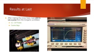
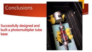
Cosmic Ray Research
BY: MATTHEW LETTERMAN
LOCK HAVEN UNIVERSITY – SENIOR TRADITIONAL PHYSICS MAJOR
ADVISOR: DR. JOHN REID
28 MARCH 2015
CPS-AAPT, MESSIAH COLLEGE
Richie LaSalle, Mackenzie Maurer, Logan Tate, Warren McDonald,
Cody Schrek, George McKinney
Outline
Introduction
Construction of a Voltage
Distribution Circuit
Conclusions
Future work
Introduction
 What are cosmic rays?
 Particles from a source outside of
earth
 Interact with the atmosphere
 Create particle showers
What can happen in showers?
(ionize, collide)
What makes it to the ground?
[muons]
Outline
Introduction
Construction of a Voltage
Distribution Circuit
Conclusions
Future work
How do we get the photomultiplier tube to see
cosmic rays?
 The photomultiplier tube (PMT) needs photons
to make an electrical signal
 Scintillators
 Two types we use – Organic (hydrocarbons) and
Inorganic (NaI)
 Scintillators work by ionization – ionize all along
path of particle
 Particle gives energy through ionization or collision
 Ionized electrons lose energy through vibrations
Photomultiplier Tubes
 How do photomultiplier tubes work?
 Use the photoelectric effect
 Electrons knocked off photocathode by
incident photon
 Electric field moves electrons
 Move from dynode to dynode
 PhotonsElectronsElectrical Signal
Photomultiplier Tube Circuits
 Each resistor will experience a
voltage difference
 Each dynode will have a different
voltage allowing for electrons to
move
1000 Volts
500 Volts400 Volts200 Volts50 Volts0 Volts
Photomultiplier Tube Base
 The base connects to the external pins
of the photomultiplier tube
 The base has a socket
 Each pin has a different electrical input
 A case is used to protect the electronics
 Different shapes and sizes
 A voltage distribution circuit – apply
different voltage to dynodes
Why build and not buy?
 Cost
 It’s not the destination, it’s
the journey!
Description Quantity Price per unit ($) Total Cost of Units ($)
Resistors 13 0.09 1.17
Capacitors 3 0.91 2.73
SHV connectors 1 15.76 15.76
Solder wick 1 3.01 3.01
BNC Connectors 2 3.15 6.30
Circuit board 1 2.49 2.49
Total Cost ($) 31.46
Where do we start?
 First looked at the photomultiplier tubes used for
Landau tests
 Used the P30CW5 built by Sens-Tech
 Looked at the specifications and narrowed down
the ones that mattered
 Photocathode spectral response, photocathode
type, photocathode active diameter, spectral
response range, output pulse, output pulse time,
and max input
 These were the guidelines to be followed for
purchasing a new photomultiplier tube
Hamamatsu
 Picked the R1924A
 Purchased two R1924A
The Base Begins
 Begin with understanding
circuit from Hamamatsu
 Figure out the values for
each resistor and capacitor
 Find all the parts needed
and make a list
1000 V
500 V
400 V200 V50 V
0 V
Design of Circuit
 Sketch: This helped to determine how
and where parts were to be soldered
 Board Assembly: This was done to see
how much space was needed for the
board
 Back Side: Made hooks for wires to be
attached
Wires Soldered to Hooks
 Wires were then soldered
to the hooks
 This made it easier to
replace or fix wires
 This was in preparation for
the wires to be soldered to
the socket
First to
Last on
Circuit
Pin # Wire #
1 1 1
2 2 2
3 14 12
4 3 3
5 13 11
6 4 4
7 12 10
8 5 5
9 11 9
10 6 6
11 10 8
12 7 7
Case Designs
 Cylindrical Design
 Box Design
 Bar Design
 Criteria:
 Light-weight
 Removable Cover
 Modifiable
 Readily Available Parts
 Time Constraints
Recycled Parts
 Used a cylindrical design that was used
with another photomultiplier tube
 Was done to save time and money (not
feasible in our time frame)
 Few Problems:
 There was nowhere to attach the board to
the rails
 The hole was too big for the socket
 Board is too big
Fixing Problems
 Advisor did work to fix the problems
 Cut a new circular plate to attach the
socket to
 Cut the board to make it small enough
to fit into the enclosure
 Drilled/Tapped holes into the rails to
attach the board
Attach wires to socket
 The socket still needed to be
wired to the circuit
 This step was tedious and fragile
 Did not want to melt the plastic of
the socket
 After the wires were attached,
some minor testing was
conducted
Initial Test
 Low voltage test
 To make sure each pin
on the socket has the
right output
Pin # Voltage
(Volts)
Dynode
Number
Voltage
(Volts)
1 19.29 K 19.29
2 13.82 1 13.82
3 10.81 2 12.28
4 8.08 3 10.81
5 5.45 4 9.42
6 2.839 5 8.08
7 0 6 6.76
8 0 7 5.45
9 0 8 4.15
10 1.447 9 2.839
11 4.15 10 1.447
12 6.76 P 0
13 9.42
14 12.28
Black Box Test
 Photomultiplier tube placed against
inorganic scintillator with optical
grease
 Used High Voltage negative power
supply
 Oscilloscope used to see output
 High voltage pushed to 1,200 volts
and no pulses were seen
Back to the drawing board
 Redesigned circuit to allow for a
high positive voltage input instead
of high negative voltage
 Two resistors and two capacitors
were added to the circuit
 One resistor and capacitor were the
same values as the rest of the circuit
 One new resistor had a large value
 One capacitor had a small value
Test 2
 Another test was done and
yet no pulses were seen
 With voltage raised up to
1,000 volts there were still
no pulses
 This made no sense and we
could not understand why
Troubleshooting
 My advisor built a
prototype circuit on a
breadboard to help find
problems
 He used the black box and
saw pulses
 I then studied this
breadboard and we
discovered wiring mistakes
in the soldered circuit
Results at Last
 After making the minor fixes, I was able to
see a pulse from the inorganic scintillator
 Cs – 137 Pulses
 Cosmic Rays
Conclusions
Successfully designed and
built a photomultiplier tube
base
Future Work
 Put circuit in a better enclosure
 Build the 2nd base for the other
photomultiplier tube
 Refining system – ringing
10 ns / div100 ms / div

Messiah Presentation

  • 1.
    Cosmic Ray Research BY:MATTHEW LETTERMAN LOCK HAVEN UNIVERSITY – SENIOR TRADITIONAL PHYSICS MAJOR ADVISOR: DR. JOHN REID 28 MARCH 2015 CPS-AAPT, MESSIAH COLLEGE
  • 2.
    Richie LaSalle, MackenzieMaurer, Logan Tate, Warren McDonald, Cody Schrek, George McKinney
  • 3.
    Outline Introduction Construction of aVoltage Distribution Circuit Conclusions Future work
  • 4.
    Introduction  What arecosmic rays?  Particles from a source outside of earth  Interact with the atmosphere  Create particle showers What can happen in showers? (ionize, collide) What makes it to the ground? [muons]
  • 5.
    Outline Introduction Construction of aVoltage Distribution Circuit Conclusions Future work
  • 6.
    How do weget the photomultiplier tube to see cosmic rays?  The photomultiplier tube (PMT) needs photons to make an electrical signal  Scintillators  Two types we use – Organic (hydrocarbons) and Inorganic (NaI)  Scintillators work by ionization – ionize all along path of particle  Particle gives energy through ionization or collision  Ionized electrons lose energy through vibrations
  • 7.
    Photomultiplier Tubes  Howdo photomultiplier tubes work?  Use the photoelectric effect  Electrons knocked off photocathode by incident photon  Electric field moves electrons  Move from dynode to dynode  PhotonsElectronsElectrical Signal
  • 8.
    Photomultiplier Tube Circuits Each resistor will experience a voltage difference  Each dynode will have a different voltage allowing for electrons to move 1000 Volts 500 Volts400 Volts200 Volts50 Volts0 Volts
  • 9.
    Photomultiplier Tube Base The base connects to the external pins of the photomultiplier tube  The base has a socket  Each pin has a different electrical input  A case is used to protect the electronics  Different shapes and sizes  A voltage distribution circuit – apply different voltage to dynodes
  • 10.
    Why build andnot buy?  Cost  It’s not the destination, it’s the journey! Description Quantity Price per unit ($) Total Cost of Units ($) Resistors 13 0.09 1.17 Capacitors 3 0.91 2.73 SHV connectors 1 15.76 15.76 Solder wick 1 3.01 3.01 BNC Connectors 2 3.15 6.30 Circuit board 1 2.49 2.49 Total Cost ($) 31.46
  • 11.
    Where do westart?  First looked at the photomultiplier tubes used for Landau tests  Used the P30CW5 built by Sens-Tech  Looked at the specifications and narrowed down the ones that mattered  Photocathode spectral response, photocathode type, photocathode active diameter, spectral response range, output pulse, output pulse time, and max input  These were the guidelines to be followed for purchasing a new photomultiplier tube
  • 12.
    Hamamatsu  Picked theR1924A  Purchased two R1924A
  • 13.
    The Base Begins Begin with understanding circuit from Hamamatsu  Figure out the values for each resistor and capacitor  Find all the parts needed and make a list 1000 V 500 V 400 V200 V50 V 0 V
  • 15.
    Design of Circuit Sketch: This helped to determine how and where parts were to be soldered  Board Assembly: This was done to see how much space was needed for the board  Back Side: Made hooks for wires to be attached
  • 16.
    Wires Soldered toHooks  Wires were then soldered to the hooks  This made it easier to replace or fix wires  This was in preparation for the wires to be soldered to the socket First to Last on Circuit Pin # Wire # 1 1 1 2 2 2 3 14 12 4 3 3 5 13 11 6 4 4 7 12 10 8 5 5 9 11 9 10 6 6 11 10 8 12 7 7
  • 17.
    Case Designs  CylindricalDesign  Box Design  Bar Design  Criteria:  Light-weight  Removable Cover  Modifiable  Readily Available Parts  Time Constraints
  • 18.
    Recycled Parts  Useda cylindrical design that was used with another photomultiplier tube  Was done to save time and money (not feasible in our time frame)  Few Problems:  There was nowhere to attach the board to the rails  The hole was too big for the socket  Board is too big
  • 19.
    Fixing Problems  Advisordid work to fix the problems  Cut a new circular plate to attach the socket to  Cut the board to make it small enough to fit into the enclosure  Drilled/Tapped holes into the rails to attach the board
  • 23.
    Attach wires tosocket  The socket still needed to be wired to the circuit  This step was tedious and fragile  Did not want to melt the plastic of the socket  After the wires were attached, some minor testing was conducted
  • 24.
    Initial Test  Lowvoltage test  To make sure each pin on the socket has the right output Pin # Voltage (Volts) Dynode Number Voltage (Volts) 1 19.29 K 19.29 2 13.82 1 13.82 3 10.81 2 12.28 4 8.08 3 10.81 5 5.45 4 9.42 6 2.839 5 8.08 7 0 6 6.76 8 0 7 5.45 9 0 8 4.15 10 1.447 9 2.839 11 4.15 10 1.447 12 6.76 P 0 13 9.42 14 12.28
  • 25.
    Black Box Test Photomultiplier tube placed against inorganic scintillator with optical grease  Used High Voltage negative power supply  Oscilloscope used to see output  High voltage pushed to 1,200 volts and no pulses were seen
  • 26.
    Back to thedrawing board  Redesigned circuit to allow for a high positive voltage input instead of high negative voltage  Two resistors and two capacitors were added to the circuit  One resistor and capacitor were the same values as the rest of the circuit  One new resistor had a large value  One capacitor had a small value
  • 27.
    Test 2  Anothertest was done and yet no pulses were seen  With voltage raised up to 1,000 volts there were still no pulses  This made no sense and we could not understand why
  • 28.
    Troubleshooting  My advisorbuilt a prototype circuit on a breadboard to help find problems  He used the black box and saw pulses  I then studied this breadboard and we discovered wiring mistakes in the soldered circuit
  • 29.
    Results at Last After making the minor fixes, I was able to see a pulse from the inorganic scintillator  Cs – 137 Pulses  Cosmic Rays
  • 30.
  • 31.
    Future Work  Putcircuit in a better enclosure  Build the 2nd base for the other photomultiplier tube  Refining system – ringing 10 ns / div100 ms / div