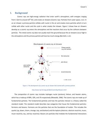
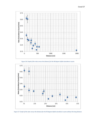
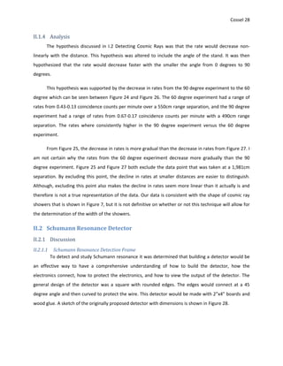
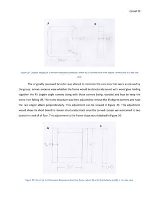
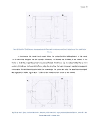
SlideShare a Scribd company logo
Cosmic Ray
Raquel Cossel
PHYS 431 Advanced Lab
Lock Haven University
Pennsylvania
Partners: Alexis Bowers, Max McIntyre, and Trevr Fernald
Advisor: Dr. John Reid
02/02/16
Cossel 1
Abstract
We studied the widths of cosmic ray showers by using scintillation counters to detect muons. We
varied the distance and angles of the detectors to study the shower profiles. We found that the shower
profile to be non-linear as expected. The shower profile decreased quicker with a smaller angle also as
expected.
We studied Schumann resonances using an inductive coil antenna that we designed and
constructed. When using our detector, we detected a signal at frequencies consistent with known
Schumann resonances.
Cossel 2
Acknowledgements
I would like to acknowledge my partners in this project, Alexis Bowers, Trevr Fernald, and Max
McIntyre, for their dedication to completing our project. My understanding of our cosmic ray research
was increased with their help. Alexis and Max’s work on the electronics, as well as, Trevr’s research for
the detectors geometry and materials was detrimental to the timely and successful completion of this
project. Our instructor, Dr. John Reid’s guidance allowed for our evolution as scientists and
understanding of research techniques. Without the support of the Lock Haven University Physics
Department, the construction of our detector would not be possible.
Cossel 3
Table of Contents
Abstract.........................................................................................................................................................1
Acknowledgements.......................................................................................................................................2
Table of Contents..........................................................................................................................................3
I. Background ...........................................................................................................................................5
I.1 Fundamental Particles ..................................................................................................................7
I.2 Detecting Cosmic Rays..................................................................................................................7
I.3 Schumann Resonance.................................................................................................................13
I.4 Lightning......................................................................................................................................16
II. Experiments ........................................................................................................................................18
II.1 Paddle Counter ...........................................................................................................................18
II.1.1 Discussion............................................................................................................................18
II.1.1.1 Assembling the Paddle Counter Stand............................................................................18
II.1.1.2 Angled Paddle Counter ...................................................................................................20
II.1.2 Procedure............................................................................................................................23
II.1.3 Data.....................................................................................................................................25
II.1.4 Analysis ...............................................................................................................................28
II.2 Schumann Resonance Detector..................................................................................................28
II.2.1 Discussion............................................................................................................................28
II.2.1.1 Schumann Resonance Detection Frame.........................................................................28
II.2.1.2 Testing for Breaks ...........................................................................................................31
II.2.1.3 Connection to Lightning..................................................................................................41
II.2.2 Procedure............................................................................................................................41
II.2.2.1 Building the Detector......................................................................................................41
II.2.2.2 Connections for the Schuman Resonance Detector.......................................................47
II.2.3 Data.....................................................................................................................................61
II.2.4 Analysis ...............................................................................................................................63
III. Summary.........................................................................................................................................64
IV. Index of Figures...............................................................................................................................65
V. Index of Tables....................................................................................................................................68
VI. Index of Equations ..........................................................................................................................68
VII. References ......................................................................................................................................68
Cossel 4
VIII. Bibliography ....................................................................................................................................69
IX. Appendix A......................................................................................................................................70
Cossel 5
I. Background
Cosmic rays are high-energy radiation that enter earth’s atmosphere, with energies ranging
from 1 GeV to around 108
TeV, and create air showers (Cosmic rays: Particles from outer space, n.d.). In
an air shower a primary particle collides with nuclei in the air and creates more particles which in turn
collide with other nuclei and this cycle is what creates the shower. Figure 1 shows how air showers
develop as a cosmic ray enters the atmosphere and the reactions that occur by the collisions between
particles. The initial cosmic ray does not usually reach the ground because the air showers occur high in
the atmosphere and the primary particle will lose too much energy (Bernlohr, n.d.).
Figure 1: The development of a cosmic-ray air shower that started with a primary particle.
http://www.mpi-hd.mpg.de/hfm/CosmicRay/Showers.html
The composition of cosmic rays includes hydrogen nuclei (protons), helium, and heavier atoms,
which has a makeup of 89%, 10%, and 1% respectively (Mewaldt, 1996). The cosmic rays are made up of
fundamental particles. The fundamental particles and how the particles interact is a theory called the
standard model. The standard model describes two categories that house the fundamental particles:
fermions and bosons. Fermions are the particles that are the foundation of matter. This includes the
quarks (up, down, charm, strange, top, and bottom) and the leptons (electron, electron neutrino, muon,
muon neutrino, tau, and tau neutrino). Bosons are particles that mediate the fundamental interactions
Cossel 6
of other particles. Bosons include gluons, photon, W±
, Z, and higgs (Elert, 1998-2015). Figure 2 is a
representation that shows the relationships between each fundamental particle. The fermions are
shown in the outer circle showing quarks (orange) and leptons (green), the bosons (blue and purple) are
the center of the circle. The higgs boson particle is separated from the other boson particles because it
is the mediator particle that gives mass to quarks, the W boson and the Z boson (Riesselmann, 2015). It
is uncertain how the higgs boson interacts with the other fundamental particles.
Figure 2: A representation of the fundamental particles and the relationships between particles.
http://www.symmetrymagazine.org/image/standard-model
Cossel 7
I.1 Fundamental Particles
Fermions are considered the “building blocks of matter” since the particles have to follow the
exclusion principle, which states that two fermions cannot be described by the same quantum number.
Therefore a cup will sit on top of a solid table instead off falling through it. The particles of the cup
cannot exist where the particles of the table exist, which is why the cup stays on top. The inability of
quarks to exist alone is why quarks are found in doublets (mesons), two bound quarks, and triplets
(baryons), three bound quarks (Elert, 1998-2015). The quarks, mesons, and baryons are also referred to
as hadrons. Hadrons encompass all combinations of quarks. Unlike quarks, leptons are able to exist on
their own. There is a subcategory of leptons called neutrinos. The neutrinos are relatively massless and
are neutral particles. The neutrino is the only particle that does not relate its mass to the Higgs-boson
particle (Neutrinos, 2015). All fermions cannot interact without the use of a mediator particle.
Bosons are the “mediator of interaction” particles. The particles are exchanged between fermions to
bind together. The gluon, photon, W+
, W-
, and Z particles are referred to as gauge bosons. The gauge
bosons are the mediators for the fundamental forces to occur (Elert, 1998-2015).
The fundamental forces of the standard model include the strong, weak, electromagnetic, and
gravitational forces. Since the gravitational force occurs on larger scale objects I will not discuss the
gravitational force. The strong force is mediated by gluons, the weak force is mediated by the W and Z
particles, and the electromagnetic force is mediated by photons.
I.2 Detecting Cosmic Rays
Cosmic rays can be detected with a cloud chamber, and other radiation detectors. Some of these
include Geiger-Mueller Counters, scintillators, and photomultiplier tubes (PMT) (Knoll, 2000). A PMT has
a photocathode that produces electrons when hit with light. The electrons emitted from the
photocathode are concentrated and directed towards the dynodes using focusing electrodes. The
dynodes multiply the electrons through the secondary-emissions phenomenon, induced discharge of
electrons caused by an initial particle colliding with a material at a sufficient energy. Each dynode is at a
higher potential then the previous dynode. A difference in potential from dynode to dynode is created
by a parallel circuit of resistors (Kleinknecht, 1998). The dynodes are arranged in multiple geometries
but each geometry’s purpose is to direct the electrons towards a dynode at a higher potential. The
electrons are then collected at the anode and converted to an electrical pulse can be viewed on an
oscilloscope (Knoll, 2000). In Figure 3 a basic geometry for the dynodes is shown in a diagram of a PMT
with the appropriate labels that show where the previously explained parts are within the tube.
Cossel 8
Figure 3: A scintillator connected to a PMT with the PMT parts labeled accordingly.
http://web.stanford.edu/group/scintillators/scintillators.html
To study cosmic ray air showers we use paddle counters (PC), also referred to as scintillation
counters, which contains a scintillator and a PMT (Isaacs, 2000). A scintillator is a material that
produced light when struck by radiation. The generated light from the scintillator passes through the
photocathode in the PMT to produce the electrons that are multiplied and shown as a pulse on the
oscilloscope. Figure 4 is a PC that we have in our lab. The scintillator is located at position a) and the
PMT is located at position b) in the picture. The scintillator is connected to the end of the PMT so that
the photocathode is aligned with it. Figure 3 above shows an illustration of how the scintillation is
utilized by the PMT to show the presence of a cosmic ray incident on the oscilloscope.
Figure 4: A paddle counter made in our lab. a) Where the scintillator is housed. b) Where the PMT is housed.
When a second PC is attached to the oscilloscope on the second channel, the pulses on the un-
triggered channel are called coincidences. These coincidences occur because the oscilloscope shows
what is occurring on the second channel when a pulse is showed on the first channel. This means that
a
b
Cossel 9
when there is a pulse on the first channel and the second channel then there is a coincidence. A
coincidence on a screen is showed on Figure 5.
Figure 5 A visual of a coincidence on an oscilloscope obtained during research.
It was hypothesized that the graph of an air shower would look like an exponential curve. There
would be a high rate of coincidences while they were close together and then the rate would decrease
the farther apart the PCs were and the drop off would not be linear. A hand drawn graph for the
hypothesized curve is shown in Figure 6.
Cossel 10
Figure 6: Hypothesized graph of the width of cosmic ray air showers.
The curve was hypothesized due to the known shape cosmic ray showers. The showers are shaped
like an elongated tear drop, as shown in Figure 7. The shower starts, begins to build, and as the cosmic
rays start to lose energy the interactions start to decrease and the shower starts to die out. It was
hypothesized that the closer the PCs are the more coincidences that will be observed, due to the shape
of the showers there would be more coincidences at the center of the air shower. It was then
hypothesized that as one counter was moved away from a stationary PC it would take longer to get a
steady amount of rates. This was determined because there are less coincidences on the outer edge of
the tear drop shape.
Cossel 11
Figure 7: Simulated cosmic ray air shower.
http://www-ekp.physik.uni-karlsruhe.de/~kandeen/images/proton_10TeV.jpg
To test the hypothesized graph from Figure 6, a stationary PC and a moveable PC were set up
attached to an oscilloscope to view the coincidences. The coincidences were then counted in a certain
amount of time. The moveable PC was then moved some distance and coincidences were counted
again. The data that was obtained is displayed in Table 1 and graphed in Figure 8. Table 1 contains the
separation of the PCs in centimeters, the amount of time that elapsed to take the measurement in
seconds, the number of coincidences that occurred within a specified time, the rate of coincidences, and
the uncertainty in the coincidences (σc) and rate of coincidences (σR).
Cossel 12
Separation
(cm)
Time
(sec)
Coincidences
(counts)
σc
(countsr^1/2)
Coincidence Rate
(counts/sec)
σR
(counts/sec)
10 60 24 4.899 0.400 0.08165
30 60 21 4.583 0.350 0.07638
50 60 14 3.742 0.233 0.06236
70 120 26 5.099 0.217 0.04249
90 120 27 5.196 0.225 0.04330
110 120 15 3.873 0.125 0.03227
130 180 19 4.359 0.106 0.02422
150 210 25 5.000 0.119 0.02381
170 240 22 4.690 0.092 0.01954
190 240 18 4.243 0.075 0.01768
210 270 26 5.099 0.096 0.01889
230 270 24 4.899 0.089 0.01814
250 270 30 5.477 0.111 0.02029
270 300 20 4.472 0.067 0.01491
290 300 22 4.690 0.073 0.01563
310 300 14 3.742 0.047 0.01247
340 360 13 3.606 0.036 0.01002
380 360 18 4.243 0.050 0.01179
Table 1: Coincidences per second obtained using Paddle Counters
Cossel 13
Figure 8: The rate of coincidences versus the distance between paddle counters.
Figure 8 is a graph of the rate of coincidences versus the distance between the paddle counters.
The error bars along the y-axis of each point show the uncertainties in the rates of coincidences. The
uncertainty of the rates includes the uncertainty in the counts. The counts were taken by hand while
watching for a coincidence to show on the oscilloscope. There is an uncertainty in each person’s ability
to track the coincidences but that is not included in the uncertainty of the rate. The trend in Figure 8 is
non-linear as was hypothesized. The data plotted in Figure 8 correlates to the hypothesized graph in
Figure 6. The counts are higher while the PCs are closer together and get closer to zero the farther apart
the PCs get. Since air showers can be around a mile wide, taking data at larger distances could produce a
curve more similar to the hypothesized curve.
I.3 Schumann Resonance
Schumann resonance is a resonance in the earth’s atmosphere that falls under the category of
extremely low frequencies (ELFs), because this resonance has its lowest Eigen-frequencies at 8, 14, 20,
26, and 32 Hz. This resonance cannot occur without an initial source of electromagnetic (EM) waves. A
good initial source of EM waves is lightening, either cloud-to-ground or cloud-to-cloud. The amplitude of
the Schumann resonance is a fraction of mV/m and it is within a 1Hz bandwidth (Simoes, et al., 2008).
Schumann resonance is being monitored by Massachusetts Institute of Technology (MIT) in
Rhode Island. MIT has two magnetic coils perpendicular to each other buried in trenches. The coils are
0.000
0.050
0.100
0.150
0.200
0.250
0.300
0.350
0.400
0.450
0.500
0 50 100 150 200 250 300 350 400
RateCoincidencecounts/sec)
Paddle Counter Separation (cm)
Cosmic Ray Coincidence Rate
Cossel 14
aligned with the geographic north-south and east-west axes. The coils are each 7 feet long, 3 inches in
diameter and permalloy cores with 30,000 turns of wire. Each coil is then encased in a PVC pipe with a 6
inch diameter that is also wound with 210 turns of wire. The 210 turns of wire is referred to as the
calibration coil and extends beyond the inner coils. The coils are used in conjunction with Polk’s original
antenna that is 10 meters high and has a spherical electrode with a radius of 15 inches (Huang, et al.,
1999).
The antenna to measure Schumann resonance has to be 10 meters high because the
resonance’s Eigen-frequencies are ELFs. The small frequencies require a larger antenna because the
small frequencies will not produce as prominent of an electrical pulse, since it will not disrupt the flux in
the smaller antenna as much. Figure 9 is a visual comparison between a high frequency (red) and a small
frequency (blue).
Figure 9: Visual comparison of high and low frequency sine waves.
https://mynameismjp.wordpress.com/2012/10/15/signal-processing-primer/
The core of the magnetic antenna needs to be isolated from the coil to avoid eddy currents from
occurring in the magnetically permeable core. Eddy currents occur on the surface of a magnetically
permeable material. The currents are induced by a change in magnetic flux and create a magnetic field
in the opposite direction of the original change in flux (Serway & Jewwtt Jr., 2004). Since the induced
currents produce a magnetic flux that opposed the original change in flux the current in the coil is
lessened and the output is smaller. Figure 10 is an illustration of eddy currents (B) that have been
induced in a magnetically permeable material (C) moving under a magnet (A). The magnetically
permeable material is moving in the direction of the purple arrows, an increase in magnetic flux is
shown by the black downward arrows, the blue circular arrows represents the induced eddy currents,
and the upward blue arrows are the induced magnetic flux to oppose the initial change in flux.
Cossel 15
Figure 10: Illustration of (A) a magnet inducing (B) eddy currents in (C) a permeable magnetic material.
To avoid the eddy currents from having a profound effect on the current in the coil and allow for
the magnetically permeability of the core to increase the antennas ability to detect the magnetic field, it
would not be ideal to use a single solid core. By using smaller insulated pieces of magnetically
permeable material, the eddy currents are decreased and unable to produce an equally large magnetic
field to oppose the original change in magnetic flux. An illustration of the difference in induced eddy
currents in a solid core versus an insulated core, as shown in Figure 11.
Figure 11: Induced eddy currents in (A) a solid core and (B) in an insulated core.
Cossel 16
I.4 Lightning
Lightning occurs because of charge separation in a cloud. Precipitation forms in clouds with ice
crystals accumulated at the top of the cloud, ice crystals and hail in the middle region of the cloud, and
the lower regions are hail and water droplets. Collisions between the precipitations result in the
precipitations becoming charged. The positively charged precipitation travels to the top of the cloud
with upward drafts and the negatively charged precipitations accumulate at the bottom of the clouds.
As the clouds charges separate the ground becomes charged as well (Understanding Lightning Science,
n.d.). Lighting does not travel directly to ground. The charge travels in steps, called stepped leaders, to
find the quickest way to the ground. When the stepped leaders are within striking distance, a distance
where the lighting is able to connect and discharge, the ground discharges a leader upwards towards the
downward lightning strike. The upwards leaders occur during the attachment process. The process of
lightning formation is illustrated in Figure 12 below.
Figure 12: The process of lightning formation with the A) stepped leader, B) striking distance,
C) connecting leaders, and D) the attachment process.
Cossel 17
Once the stepped leaders attach to the leader the charge in the cloud is able to discharge. The
negative charges travel to the ground and the return stroke, which is when light travels through the
connected path from the ground to the cloud. In Figure 13A, the direction that the negative charge
travels during discharge is shown by the arrows traveling towards the ground, and in Figure 13B the
arrows are the direction that light travels during the return stroke. The flashes that are seen during and
after the initial lightning strike, or the lingering light after the strike, is caused by dart leaders. The dart
leaders are the cloud discharging the negative charge that is left after the initial lighting strike. This
negative charge and the return strokes only travel the main path of the connected lightning path. Figure
14A shows the direction of the discharge in the dart leader and Figure 14B shows the path that light
travels in the following return stroke. As you can see in Figure 14, the branches from the initial lighting
strike from Figure 13 are no longer used when the dart leader and the following return stroke occur.
Once the cloud has discharged and the dart leader can no longer travel the current path from the
connected lightning, the process starts over with the separation of charges (Uman, 1987).
Figure 13: The direction of A) negative charge discharge in the initial lightning strike
and B) light travel in the return stroke.
Cossel 18
Figure 14: The direction of A) negative charge discharge and B) light travel in dart leaders.
II. Experiments
II.1 Paddle Counter
II.1.1 Discussion
II.1.1.1 Assembling the Paddle Counter Stand
The stand for the paddle counter was constructed using already preassembled structures that a
previous research group built. The stand consists of a wooden base and wooden frame used to hold the
paddle counters in parallel at a fixed distance. The base requires the braces to be screwed together
where the A and B markers align on each side. The frame is then attached to the stand with long bolts.
The stand is wider than the frame. To fill the space between the frame and the stand and to keep the
frame centered, wooden blocks with holes in the center are placed between the frame and stand. The
PCs are then screwed onto the frame. There are eye hooks to attach rope to that will hold the frame at
the desired angles. Figure 15 is a picture of the stand, frame, and PCs assembled.
Cossel 19
Figure 15: Paddle Counter stand with paddle counters and connections securely attached.
The power cord and BNC cable for the attached paddle counters were secured to the frame and
stand, using zip ties, so that when the PC’s angle was changed the cords did not get caught on the stand.
To determine if the cords would get caught on the stand, the PCs were rotated 90 degrees up and down
and then the cables were attached. Figure 16 and Figure 17 are images of the cables attached to the
frame and the stand with zip ties.
Figure 16: Paddle counter attached to the frame with the connections secured to the frame with zip ties.
Cossel 20
Figure 17: The secured paddle counter connections attached to the stand with zip ties.
II.1.1.2 Angled Paddle Counter
To determine the angle of air showers, an experiment was proposed to measure coincidences
between three PCs. To do this two PCs were attached to the stand that was assembled and a third PC
was placed on a moveable table. By changing the angle of the stand and adjusting the movable table
away from the stand the occurrence of coincidences should decrease the farther away. The stands angle
is then adjusted and the table is moved again. Diagrams of the experiment setup are shown in Figure 18,
Figure 19, and Figure 20.
Cossel 21
Figure 18: Paddle counter setup perpendicular to the ground where A) is a frontal view and B) is a side view.
Figure 19: Paddle counter setup at 45 degree angle from the floor, where A) is the frontal view and B) is a side view.
Figure 20: Paddle counter stand setup with the paddle counter on the moveable table.
Cossel 22
To keep track of the triple coincidences a DAQ board was required since the oscilloscopes only
have two signal inputs. The DAQ board has four inputs so it can detect four-fold coincidences. The user
should know how to program the board using hex. To enable the proper inputs when detecting
coincidences, the computer software has to be programmed accordingly. The number of coincidences
and the enabled channels are programmed using different code. Table 2 is a table that shows all the
codes possible for this DAQ board and our use. The 0’s in the table represent the disabled inputs and the
1’s are the enabled inputs. The code for programming the type of coincidence to be taken is shown in
Table 3.
Hex
Code
Inputs
0 1 2 3
0 0 0 0 0
1 0 0 0 1
2 0 0 1 0
3 0 0 1 1
4 0 1 0 0
5 0 1 0 1
6 0 1 1 0
7 0 1 1 1
8 1 0 0 0
9 1 0 0 1
A 1 0 1 0
B 1 0 1 1
C 1 1 0 0
D 1 1 0 1
E 1 1 1 0
F 1 1 1 1
Table 2: Hex code for enabled and disabled inputs.
Coincidence
Hex
Code
Single-Fold 0
Double-Fold 1
Triple-Fold 2
Quadruple-
Fold
3
Table 3: The type of coincidence and its corresponding Hex code.
Cossel 23
II.1.2 Procedure
The set up described above was assembled using the stand, a moveable table, and the three
PCs. Using masking tape we measured the distance on the floor and marked each meter as shown in
Figure 21. Then we used tape to mark the table top and the PC so that it could be realigned each time
shown in Figure 22, and then taped the bottom on the table so that it could be aligned with the floor
each time it was moved as shown in Figure 23. The DAQ board was set to allow three-fold coincidence
counts. The PC was moved to different distances and coincidence counts were taken. The code used to
take three-fold coincidence counts for this experiment is WC 00 23. This code means that three-fold
coincidence counts are taken of the enabled input 0, 1, and 2.
Figure 21: The paddle counter on the moveable table aligned with the tape on the floor.
Figure 22: The paddle counter aligned with the tape on the table top.
Cossel 24
Figure 23: The tape on the bottom of the table aligned with the tape on the floor.
Since the collection of trifold coincidence counts takes a substantial amount of time, 60 degrees
and 90 degrees have been successfully completed. The data is located in the following section. Table 4 is
the data obtained from the 60 degree trifold coincidence count which includes time, distance between
the PCs, the number of coincidence counts and its uncertainty, and the rate of coincidence counts and
its uncertainty. Figure 24 is the graph of the 60 degree experiment rates versus distance with the rates
uncertainty as positive and negative error bars. Figure 25 is the graph of the 60 degree experiment rates
versus distance without the data point that was taken at a large distance between the stand and the
moveable table. Table 5 is the data obtained from the 90 degree experiment which includes the time,
distance of the stand and moveable PC, the count of the coincidences and its uncertainty, and the rate
of the coincidence count and its uncertainty. The data from Table 5 is graphed in Figure 26, which is the
rate of the coincidences graphed against the distance with positive and negative error bars from the
rates uncertainty. Figure 27 is the rate of the 90 degree experiment versus the distance without the
large distance data point.
Cossel 25
II.1.3 Data
Time (min) Distance (cm)
Coincidences
(counts)
σCoincidences
(counts^1/2)
Rate
(Counts/min)
σRate
(Count/min)
1441.02 462 255 15.969 0.18 0.0111
1348.2 320 268 16.371 0.20 0.0121
312 120 112 10.583 0.36 0.0339
1008 380 205 14.318 0.20 0.0142
4317 317 859 29.309 0.20 0.0068
1560 220 347 18.628 0.22 0.0119
1506 70 643 25.357 0.43 0.0168
1279.8 150 406 20.149 0.32 0.0157
325.8 258 107 10.344 0.33 0.0317
1050 620 140 11.832 0.13 0.0113
3127.8 500 440 20.976 0.14 0.0067
3750 1981 204 14.283 0.05 0.0038
Table 4: Data obtained from the 60 Degree trifold coincidence counts.
Figure 24: Graph of the rates versus the distance for the 60 degree trifold coincidence counts.
0.04
0.09
0.14
0.19
0.24
0.29
0.34
0.39
0.44
0 200 400 600 800 1000 1200 1400 1600 1800 2000
Rate(CoincidenceCounts/min)
Distance (cm)
Cossel 26
Figure 25: Graph of the rates versus the distance for the 60 degree trifold coincidence counts without the long distance.
Time (min) Distance (cm)
Coincidence
(counts)
σCoincidence
(counts^1/2)
Rate
(counts/min)
σRate
(Counts/min)
1009 78 677 26.0192237 0.67096135 0.02578714
187 122 123 11.0905365 0.65775401 0.05930768
1404 560 313 17.691806 0.22293447 0.012601
1013 480 228 15.0996689 0.22507404 0.01490589
373 410 101 10.0498756 0.27077748 0.02694337
1414 302 279 16.7032931 0.19731259 0.0118128
280 250 80 8.94427191 0.28571429 0.03194383
882 78 357 18.8944436 0.4047619 0.02142227
306 122 104 10.198039 0.33986928 0.03332692
1287 165 420 20.4939015 0.32634033 0.01592378
343 260 112 10.5830052 0.32653061 0.03085424
935 339 228 15.0996689 0.24385027 0.01614938
4515 460 796 28.213472 0.17630122 0.00624883
4073 1981 689 26.2488095 0.16916278 0.00644459
Table 5: Data obtained from the 90 degree trifold coincidence counts.
0.10
0.15
0.20
0.25
0.30
0.35
0.40
0.45
50 150 250 350 450 550 650
Rates(CoincidenceCounts/min)
Distance (cm)
Cossel 27
Figure 26: Graph of the rates versus the distance for the 90 degree trifold coincidence counts.
Figure 27: Graph of the rates versus the distance for the 90 degree trifold coincidence counts without the long distance.
0.15
0.25
0.35
0.45
0.55
0.65
0.75
0 500 1000 1500 2000
Rate(CoincidenceCounts/min)
Distance (cm)
0.15
0.25
0.35
0.45
0.55
0.65
0.75
75 175 275 375 475 575
Rates(CoincidenceCounts/min)
Distance (cm)
Cossel 28
II.1.4 Analysis
The hypothesis discussed in I.2 Detecting Cosmic Rays was that the rate would decrease non-
linearly with the distance. This hypothesis was altered to include the angle of the stand. It was then
hypothesized that the rate would decrease faster with the smaller the angle from 0 degrees to 90
degrees.
This hypothesis was supported by the decrease in rates from the 90 degree experiment to the 60
degree which can be seen between Figure 24 and Figure 26. The 60 degree experiment had a range of
rates from 0.43-0.13 coincidence counts per minute over a 550cm range separation, and the 90 degree
experiment had a range of rates from 0.67-0.17 coincidence counts per minute with a 490cm range
separation. The rates where consistently higher in the 90 degree experiment versus the 60 degree
experiment.
From Figure 25, the decrease in rates is more gradual than the decrease in rates from Figure 27. I
am not certain why the rates from the 60 degree experiment decrease more gradually than the 90
degree experiment. Figure 25 and Figure 27 both exclude the data point that was taken at a 1,981cm
separation. By excluding this point, the decline in rates at smaller distances are easier to distinguish.
Although, excluding this point also makes the decline in rates seem more linear than it actually is and
therefore is not a true representation of the data. Our data is consistent with the shape of cosmic ray
showers that is shown in Figure 7, but it is not definitive on whether or not this technique will allow for
the determination of the width of the showers.
II.2 Schumann Resonance Detector
II.2.1 Discussion
II.2.1.1 Schumann Resonance Detection Frame
To detect and study Schumann resonance it was determined that building a detector would be
an effective way to have a comprehensive understanding of how to build the detector, how the
electronics connect, how to protect the electronics, and how to view the output of the detector. The
general design of the detector was a square with rounded edges. The edges would connect at a 45
degree angle and then curved to protect the wire. This detector would be made with 2”x4” boards and
wood glue. A sketch of the originally proposed detector with dimensions is shown in Figure 28.
Cossel 29
Figure 28: Original design for Schumann resonance detector, where A) is a frontal view with angled corners and B) is the side
view.
The originally proposed detector was altered to minimize the concerns that were expressed by
the group. A few concerns were whether the frame would be structurally sound with wood glue holding
together the 45 degree angle corners along with those corners being rounded and how to keep the
wires from falling off. The frame structure was then adjusted to remove the 45 degree corners and have
the two edged attach perpendicularly. This adjustment can be viewed in Figure 29. This adjustment
would allow the short board to remain structurally intact since the curved corners was contained to two
boards instead of all four. This adjustment to the frame shape was sketched in Figure 30.
Figure 29: Sketch of the Schumann Resonance detection frame, where A) is the frontal view and B) is the side view.
Cossel 30
Figure 30: Sketch of the Schumann Resonance detection frame with curved corners, where A) is the frontal view and B) is the
side view.
To ensure that the frame is structurally sound the group discussed adding braces to the frame.
The braces were designed for two separate functions. The braces are attached at the corners of the
frame so that the perpendicular corners are reinforced. The braces are also attached to that a small
portion of the brace sits beyond the frame edge. By attaching the brace this way it also becomes a guide
for the wire that will be wrapped around the outer edge. The guides will keep the wire from slipping off
the edges of the frame. Figure 31 is a sketch of the frame with the braces at the corners.
Figure 31: Sketch of the Schumann Resonance detection frame with curved edges and triangular corner braces, where A) is the
frontal view and B) is the side view.
Cossel 31
II.2.1.2 Testing for Breaks
A concern when wrapping the wire around the frame is the uncertainty of whether the wire has
broken during the process. By finding a solution to determine if the wire had broken and at what
distance it broke, there is a chance that the wire could be fixed before the detector is completed. A
proposed method to test for a break in the wire is to send a pulse down the wire, determining how long
the pulse’s reflection took to return, and then determining the distance travelled by the reflection. If
the distance travelled is less than the amount of wire that is on the detector, then the wire is broken
and the distance that was calculated is where the break in the wire is. By using the speed of light and a
wire with a known length, it is possible to determine the amount of time it would take the reflection to
return. To get a reflection the pulse would have to be sent down a wire where the one end is
unattached. The reflection would hit a fixed end and return inverted, since the unattached end would
act as a node for the pulse. In the wire the pulse is an electromagnetic wave
The pulse was expected to return inverted based off of the concept of a pulse traveling down a
string to a fixed end. In a string when a pulse travels down to a fixed end, it returns inverted. When the
pulse reaches the end of the string, it creates an upward force on the boundary. Since the boundary is
stationary before the pulse acts on it, the boundary would supply a reaction force thus creating a
downward force on the string. By creating this downward force the pulse’s reflection would then return
inverted. An illustration of a pulse travelling down a string that has a fixed end is shown in Figure 32,
where a pulse is travelling towards the fixed end and then travelling away from the fixed end inverted. If
the pulse returns non-inverted then the end is considered a free end.
Figure 32: A pulse travelling down a string, where A) the pulse is travelling towards another medium and B) the inverted pulse
travelling away from the other medium.
Cossel 32
The pulse does not invert with a free end because there is not a reaction force. The pulse
therefore does not create a force that would cause an inverted pulse. Figure 33 is an illustration of a
pulse travelling down a string with a free end, where the string is travelling towards the free end and
then away from the free end non-inverted. (Serway & Jewwtt Jr., 2004).
Figure 33: A pulse travelling down a string with a free end, where A) is the pulse traveling to right and B) the pulse is travelling to
the left.
Before testing this method, we did a calculation to determine how long the reflection would
take to return by using a known length of wire. The known length of wire was 9m. The calculation
determined the reflection would return in 30ns. To be able to see the pulse and reflection, a pulse with
a width on the nanoscale was required. The only way to get a pulse on the nanoscale in our lab would be
to use a paddle counter (PC) and cosmic rays. The cosmic ray signal is enlarged by the photomultiplier
tube (PMT) and can be seen on the oscilloscope with a scale of at least 10ns. With the reflections
determined to take 30ns to return, the pulse would need to be viewed on the nanoscale as well. To test
this process, it was determined that it would be best to connect a PC to an oscilloscope and a wire with
an unattached end with a t-connector so the pulse and its reflection could be seen on the same
oscilloscope channel. Figure 34 is a depiction of the proposed set up.
Figure 34: Proposed set up to determine pulse reflections, where A) is the paddle counter, B) is the oscilloscope, and C) is the
wire with an unattached end
Cossel 33
Pulses were visible when the PC was connected to the oscilloscope and the settings were
adjusted on the oscilloscope accordingly. Then the wire was attached to the oscilloscope and the other
end was unattached. A pulse and its reflection were then visible on the oscilloscope channel. There were
two obvious differences in the reflection than was expected. The differences in the reflection is that it
was not inverted and that the reflection took longer to return than was expected. From this, I concluded
that these wire’s unattached ends acted as a loose end instead of a fixed end. I do not have an
explanation for why the wire is behaving as a loose end. The reflection of the pulse was not inverted and
the reflection was at twice the distance that was calculated. The reflection returning in twice the
amount of time than what was expected was due to there being a difference between the cable length
and the distance the pulse had to travel to be seen on the oscilloscope a second time. The distance the
pulse travelled was twice the wire length because the pulse had to travel to the end of the wire and
then be reflected back to the oscilloscope make the total distance twice the cable length. Taking this
into account the known length was then 18m making the calculated time for the reflection to appear to
be 60ns. Even after adjusting the cable length we realized the pulse’s reflection did not return after
60ns. The reflection’s return to the oscilloscope took longer than 60ns, which meant that the pulse was
not travelling at the speed of light. To determine the speed that the pulse and its reflection are
travelling, multiple wire lengths were used and the amount of time the reflection took to appear was
studied.
To measure the time between the pulse and its reflection, the run/stop mode on the
oscilloscope was used to capture and image of the pulse and reflection and then the vertical bar mode
was used to measure the time. The vertical bar mode was also used to determine the uncertainty in
where the pulse started. This procedure was used to collect data with multiple wire lengths. Figure 35 is
a pulse and its reflection on the oscilloscope. The reflection is not inverted and is wider than the pulse,
which is due to dispersion while the pulse and the reflection travel through the wire
Cossel 34
Figure 35: A cosmic ray pulse and the reflected pulse after travelling the distance of the distance to the end of the wire and back
to the oscilloscope.
While experimenting with the wire lengths, it became clear that the unattached wire had to be
long enough so that a pulse and its reflection could be viewed as two separate and measurable pulses,
as seen in Figure 36. If the unattached wire was too short, the pulse from the PC was visible but the
reflection travelled down the wire and back so quickly that it was undistinguishable from the pulse and
the multiple reflections after it. Figure 36 shows the clearly distinguishable original pulse but after that it
just looks like noise. To find the minimum length of wire need to see a pulse and distinguishable
reflection, multiple wires were connected until a reflection was viewed. Figure 37 is a pulse and
reflection using the shortest length of wire that reflected a measureable pulse and reflection. This
reflection occurred with a wire that had a length of 3.35m. The reflection in Figure 37 shows that its
width is larger than the pulse due to dispersion and the reflection is more than 20ns after the pulse,
which correlates with travelled distance greater than 6m.
Figure 36: A cosmic ray pulse followed by the noise caused by the reflected pulse from a short cable.
Cossel 35
Figure 37: A cosmic ray pulse and the reflected pulse with the shortest length cable without noise.
Since all of the wires of varying length, used to take data, were all BNC cables a linear trend in
the data was hypothesized. This was hypothesized because regardless of the size of the pulse, the pulse
and the reflection would be travelling down the same type of wire each time. This meant the speed the
pulse and the reflection travelled did not depend on the length of the wire in any way. Although, the
speed that the pulse and reflection travel could change depending on the type of wire being used.
The data that was obtained by using multiple length wires was recorded in Table 6. The table
includes the distance travelled by the pulse and reflection, the amount of time that passed between the
original pulse and the reflections return, the least count of the oscilloscope for the settings that were
used for each data point, the uncertainty in what was considered the beginning of each pulse and the
total uncertainty in the reflections return time. Table 7 is the data used to plot a weighted fit for the
data in Table 6. From the weighted fit it was determined that the slope, m, of the fit was 5.05E-09 s/m
and the y-intercept, b, is 2.80E-10 s. The speed of the reflection’s travelled distance, the total distance of
the unattached wire, is one over the slope. The speed was calculated to be 1.98E+08 m/s with an
uncertainty of +/- 0.0342E+08 m/s, which is slower than the speed of light. The speed was calculated
using Equation A1 and the uncertainty was calculated using Equation A2, which are listed in Appendix A.
With this uncertainty, the speed of the pulse and reflection is between 1.95E+08 m/s and 2.01E+08m/s.
A speed slower than the speed of light is an adequate speed since there are imperfections in the
material which would cause the pulse and reflection to travel slower.
Cossel 36
The data from Table 6 and Table 7 are graphed in Figure 38. The graph contains the amount of
time the reflection took to return plotted against the total distance the reflection had to travel. The
individual data points, blue, are listed in Table 6 and the error bars are the +/- of the total uncertainty in
the reflection. The solid green line is the weighted fit that was calculated using the data from Table 6
and is shown in Table 7. There is a clear linear trend in the data that corresponds to our hypothesis.
Distance Travelled
(m)
Reflection
(s)
Least Count
(s)
Uncertainty in
Pulse (s)
Uncertainty in
Reflection (s)
18.29 9.28E-08 4.00E-09 6.00E-10 4.04E-09
36.58 1.87E-07 4.00E-09 4.00E-10 4.02E-09
30.78 1.54E-07 4.00E-09 5.00E-10 4.03E-09
67.36 3.42E-07 8.00E-09 8.00E-10 8.04E-09
49.07 2.48E-07 8.00E-09 8.00E-10 8.04E-09
61.57 3.10E-07 8.00E-09 5.00E-10 8.02E-09
79.86 4.03E-07 8.00E-09 9.00E-10 8.05E-09
98.14 4.96E-07 8.00E-09 7.00E-10 8.03E-09
Table 6: Cosmic ray pulse and reflected pulse data obtained through experimentation.
Cossel 37
m (s/m) x (m) y (s)
5.05E-09 15.00 7.61E-08
Δm (s/m) 20.00 1.01E-07
8.72E-11 25.00 1.27E-07
b (s) 35.00 1.77E-07
2.80E-10 40.00 2.02E-07
Δb (s) 45.00 2.28E-07
4.09E-09 50.00 2.53E-07
v (m/s) 55.00 2.78E-07
1.98E+08 60.00 3.03E-07
σv (m/s) 65.00 3.29E-07
0.0342E+08 70.00 3.54E-07
75.00 3.79E-07
80.00 4.04E-07
85.00 4.30E-07
90.00 4.55E-07
95.00 4.80E-07
100.00 5.06E-07
Table 7: Values obtained from a weighted fit for cosmic ray pulses and reflected pulses.
Cossel 38
Figure 38: A graph of the time for the reflection to return versus the total distance travelled by the pulse and a weighted fit of
the data.
To further understand if using pulses to test for breaks is a possible technique, a solid copper
core wire cut to a length of 9.144 meters was studied. To eliminate the noise caused by the cut wire
acting like an antenna, the coil was wrapped in aluminum foil with the two ends sticking out from the
foil as to not ground the wire. The coil was then attached at one end to the oscilloscope and PC and the
other end was left free. The same set up was used as was shown in Figure 34 with the addition of
aluminum foil encasing the wire. Figure 39 shows the set up with the PC, oscilloscope, and aluminum foil
encased coil of wire. Before wrapping the coil with aluminum is was not possible to see a reflected pulse
because the noise was stronger than the pulse that was being viewed. With the coil in aluminum foil a
pulse and reflection were visible.
y = 5.05E-09 x + 2.80E-10
Cossel 39
Figure 39: The set up for testing a known length of solid copper core wire, where A) is the paddle counter, B) is the oscilloscope,
and C) is the wire wrapped in aluminum with the unattached end sticking out from the aluminum.
At first the unattached end of the wire was also enclosed in the aluminum foil and a reflection
was not visible on the oscilloscope. With the unattached end in the aluminum foil it was not possible to
tell if the wire was being unintentionally grounded. To remedy this, both ends of the wire were not
enclosed in the aluminum foil. Once the unattached end of the wire was removed from the aluminum
foil a reflection was then visible. Figure 40 is a pulse with a reflection at 108ns. The reflection travels
even slower in this wire than the original experiment. Using the speed of 2E+08 m/s that was obtained
from Figure 41, the reflection should appear around 90ns. To determine if the pulse was traveling
slower than the experimental speed, we attached the free end of the coil to channel 2 on the
oscilloscope. By attaching the free end, we will see a delayed pulse instead of a reflection of the pulse.
Figure 40: A pulse and reflection obtained by using a solid copper core bell wire.
By attaching the originally unattached end, the pulse and the delayed pulse can be seen side by
side on the oscilloscope. The set up described for the delayed pulse is depicted in Figure 41. The paddle
counter is attached to the oscilloscope and wire and shown as channel 1, which is yellow and the other
Cossel 40
end of the coil is attached to the oscilloscope and is shown as channel 2, which is blue. To determine
where the delayed pulse will appear requires an alteration to the calculations. The distance the pulse
travels is now half of what the reflection travelled, since the pulse travels through the wire and then
directly to the oscilloscope. The delayed pulse was expected to appear at 45ns. The delayed pulse was
actually viewed at 54ns. Seeing the delayed pulse at 54ns shows that the pulse is in fact moving slower
than the experimental speed of 2E+08m/s and that the reflection at 108ns is a true reflection. The
delayed pulse is the channel in blue, shown in Figure 42, and the yellow is the original pulse. The ability
to see the reflection in the solid copper core wire was a promising step towards determine if there are
breaks in the wire while the detection coil is being wound.
Figure 41: The delayed pulse set up, where A) is the paddle counter, B) is the oscilloscope, and C) is the aluminum foil encased
coil connected to the oscilloscope by what was the unattached end.
Figure 42: A pulse in yellow and the delayed pulse in blue obtained by using a solid copper core bell wire.
Cossel 41
To further determine if this process would work on the thin wire that is to be used to make the
coil on the detector, a smaller diameter wire than the solid copper core wire was used. Unfortunately,
even enclosing the coil in aluminum foil did not help in eliminating enough noise to look for a reflection
from the pulse. Even using the delayed pulse method to study the wire was not very informative. The
wire produced a similar delayed pulse each time a pulse was detected but there was no way to
determine the delayed pulse actually started. From these poor result with a wire more similar in size to
the desired coil wire, it was determined that this overall method for determining if the wire has broken
while the coil is being wrapped around the frame is not plausible. The pulse reflection is most likely too
dispersed to be viewed on the oscilloscope.
II.2.1.3 Connection to Lightning.
Lightning return strokes caught my attention because of the returns strokes similarity to my
experiment with BNC cables to test for breaks in our Schumann resonance detector. The variation in the
electric field graphs looked extremely similar to the pictures of the oscilloscope that I viewed when
looking for pulse reflections. The electric field graphs show a large spike on the electric field when the
return stroke occurs and then smaller changes in the electric field for each dart leader return stroke that
occurred after the initial return stroke. The way charges travel when lightning strikes the ground
resembled how charges travel in wires. By using an oscilloscope, a PC, t-connectors, and multiple BNC
cables of varying length, I will send pulses down the wires and try to predict where the reflections will
return to the oscilloscope. My goal is to see if I can draw a conclusion on whether or not the paths
created during a lightning strike act like wires.
II.2.2 Procedure
II.2.2.1 Building the Detector
To build the Schumann resonance detection frame the first step was to cut the two 2”x4”
boards into two 34” boards and two 41” boards. To cut the appropriate length boards, the tools that
were used included a saw, a square, and a tape measurer. Figure 43 is a picture of the board being cut
with a saw after being measured and marked. This was done to obtain four boards.
Cossel 42
Figure 43: Cutting the boards for the frame using a saw.
The two 41” boards are to have two corners rounded. To achieve the rounded corners, a
compass was used to draw the guides for the curve. A straight edge was used to draw two lines tangent
to the curve so a rough cut could be made. Figure 44 is a picture of the frame edge after the rough cuts
were made. A saw was also used to make the rough cuts. A sander was then used to remove the excess
wood from the board and to smooth out the final curve of the wood. Figure 45 is a picture of the
smooth curve. This process was repeated for three additional curved corners.
Figure 44: The curved edge after rough cuts were made.
Cossel 43
Figure 45: The curved edge after the rough cut was smoothed out.
After the corners were smoothed, the next step was to remove the rounded edges that ran the
entire length of the boards. These edges needed to be removed to the wire would lay flat and parallel
along the entire width of the board. The curved edges were removed using a table saw. Figure 46 shows
the board positioned against the saw. This shows that a small amount of the wood was removed. Figure
47 is a comparison of one board before it was cut and one board after having been cut. In Figure 47 the
curved edges are clearly removed from the top of the board and that the edges are sharp edges. The
boards were then clamped together and an electric sander was used to smooth out the cuts so one
board does not end up shorter than the others. The boards being clamped together is shown in Figure
48 at two different angles.
Figure 46: The board positioned against the table saw.
Cossel 44
Figure 47: A comparison of the two boards, where (A) a board has had the rounded edges and
(B) a board before the rounded edges were removed.
Figure 48: The perimeter boards clamped together before being sanded from (A) angle one and (B) angle two.
To make sure the frame is structurally sound triangle braces were cut with a hand saw. Figure 49
is the braces for one side of the frame. Only one side of braces could be attached at a time because the
wood glue needs at least 24 hours to set. The other side was cut and glued at a later time. The frame
was then laid out on the table, the edges were aligned and squared, and the braces were held on with
clamps after that corner was adjusted. Figure 50 shows the braces and frame being held in place. The
braces were traced onto the frame so that after glue was applied the braces could be realigned more
easily. After the brace was glued and aligned the braces were clamped in place and then temporarily
screwed to the frame. Figure 50 shows the frame aligned and clamped before being attached and Figure
A B
Cossel 45
51 is after all elements were attached. In Figure 52 you can see the corner brace after it was glued to the
frame and the temporary screws were placed. The second set of braces were attached a few days later
with the same process of clamping the braces in place, traced, glued and then temporary screws placed.
Figure 53 shows the side of a corner of the frame with both braces in place.
Figure 49: Triangle braces for one side of the frame.
Figure 50: Schumann resonance detection frame before each element was attached.
Cossel 46
Figure 51: Schumann resonance detection frame after all elements have been attached.
Figure 52: A corner brace of the Schumann resonance detection frame with the temporary screws.
Cossel 47
Figure 53: A corner of the Schumann resonance detection frame after the second set of braces were attached to the frame.
II.2.2.2 Connections for the Schuman Resonance Detector
To be able to view the resonances that are to be detected, the detector needs to be able to
connect to the oscilloscope. To connect to the oscilloscope the wire that is to make the coil has to be
connected to a BNC cable in some way. The proposed way to connect the wire to the BNC cable is
through a connector that has a pin to solder a wire to and a female BNC connection on the other end, as
shown in Figure 54. From Figure 54 the wire was soldered to the gold pin on the left of the nut and the
male BNC connector were attached to the female BNC connector on the right of the nut.
Figure 54: BNC female connection to a wire connector.
http://www.showmecables.com/product/BNC-Female-Chassis-Mount-Connector.aspx
Cossel 48
To attach this connector to the frame, a hole was cut into one of the braces and the solder pin
and ground was inside the two braces and the female BNC was on the outside of the brace. This idea is
shown in Figure 55 shows the connection between the two corner braces, A, the connection on the
outside of the corner board, B, and the side view of the connection, C. In Figure 55, there is also a
thicker wire connected to the connector and then connected to the wire used for the coil. This thicker
wire is meant to remove strain off of the coil wire and the goal is to avoid a break in the wire causing a
faulty connection.
Figure 55: Female BNC connector connected to the wood corner brace, where A) is the connection between the two corner
braces, B) is the connection on the outside of the corner brace, and C) is the side view of the connection.
A concern with the connection being attached directly to the corner brace was that the pin
would be in the way when wrapping the coil. To remedy this, the connector was attached to a piece of
hard plastic and then connected to the wood corner brace. The hole in the corner brace was larger than
the connector so that the nut that attached the connector to the plastic could be accessed if the
connector needed to be removed at some later time. Figure 56 is a depiction of the connector being
attached to the corner brace after being attached to a piece of hard plastic and shows the connection
inside the two corner braces, the connection of the connector and plastic to the outside of the corner
brace, the side view of the connection, and an enlarged side view of the plastic/connector being
attached to the wood corner brace.
Cossel 49
Figure 56: BNC to wire connector connected to plastic and attached to the wood corner brace, where A) is the connection
between two corner braces, B) is the connector and plastic attached to the outside of the corner brace, C) is a side view of the
connector attached to the corner brace and D) is an enlarged view of the connector being attached to the corner brace.
A prototype of the sketched connection in Figure 56 was made with a piece of wood the
thickness of a corner brace with a predrilled hole, plastic with a predrilled hole, a female BNC connector
similar to Figure 54, and tape. A predrilled hole was enlarged to fit the BNC connector. The female BNC
connector was on one side and the ground and nut on the side of the pin as shown in Figure 57. The
plastic was then attached to the wood with the pin and ground sitting inside of the hole in the wood as
shown in Figure 58. Figure 59 shows the female BNC connector attached to the plastic which is attached
to the wood on the outside of the corner brace. The side view of the prototype, Figure 60, shows that
the pin sits within the hole that is in the wood, and did not interfere with wrapping the wire around the
frame. The ground, however, sticks out of the hole in the wood but the ground can we shortened to fit
within the hole. A hole was easily widened in the plastic to make it large enough to fit the connector. It
has not been determined how to cut the plastic down to a reasonable size to attach to the outside of the
corner brace on the frame. Over all the prototype was successful. Figure 61 is the plastic for the BNC
connector glued to the wooden frame from two angles and Figure 62 is the soldered BNC connector that
is going to be used to on the detector.
Cossel 50
Figure 57: Female BNC to wire connector attached to a piece of hard plastic.
Figure 58: Inside view of the BNC to wire connection prototype, which shows the pin and ground inside the hole in the wood.
Cossel 51
Figure 59: Outside view of the BNC to wire connector attached to the connection prototype, where the female BNC connection is
attached to the plastic on the outside of the hole in the wood.
Figure 60: Side view of the BNC to wire connector that is attached to the prototype connection, where the pin and ground are on
the left of the wood and the female BNC connector is on the right of the wood and plastic.
Cossel 52
Figure 61: Glued plastic connector for the BNC connection showing A) the front of the connection and B) the side of the
connection.
Figure 62: Soldered BNC connector for the detector.
A B
Cossel 53
To connect the coil on the detector to the BNC female connector, it was determined that it
would be better to connect the coil to a panel and then use a thicker wire to connect the panel to the
BNC connector. Several prototypes were made to determine the best way to attach the coil wire and
thick wire to the panel. Figure 63 is a prototype that has the wires stick through the panel and soldered
on the underside. This prototype was dismissed because the solder was too large and would cause a
problem when gluing the panel to the wooden detection frame. Figure 64 is a prototype where the wire
were wrapped through the panel and then twisted around itself and soldered on the underside. This was
also dismissed because it would not connect easily to the wooden detection frame. Figure 65 is a
prototype that was chosen to be used on our detector. The wires are placed into the holes on the panel
and then soldered. The back of the panel is flat and was then glued to a piece of wood.
Figure 63: Panel connection prototype where the wires are through the panel and then soldered.
Cossel 54
Figure 64: A prototype connection where the wire are A) soldered after being B) pulled through the panel and wrapped aroung
itself.
Figure 65: Panel connection prototype where the wires are soldered while sitting in the panel and then glued to a board.
A B
Cossel 55
After deciding on a panel and soldering technique, the next step was how to keep the coil under
tension if the soldered connection at the panel were to break. The proposed solution was a post
constructed by a bolt that had plastic washers and were held on by a nut. The prototype is shown in
Figure 66, with a thin wire used to mimic the wire that is to be used to wrap the coil. Figure 67 is a
prototype of the connection of the wire from the post to the connection panel.
Figure 66: Prototype post that will hold the tension of the coil.
Figure 67: Prototype panel connection to a post.
Cossel 56
The desired prototypes were then implemented on our detector frame. Figure 68 shows the bolt
that was used as the post after being placed onto the frame. The bolt is covered with heat shrink to
protect the thin wire from the treads on the bolt. Figure 68 shows three different angles of the post in
the frame. Figure 69 shows the post in the frame with the heat shrink, the two plastic washers, and the
nut. The washers are used to protect the wire from being damaged by the wooden frame and the nut
when it is tightened. Figure 69 shows the post with the washers and nut loose on the post as well as
tightened on the bolt. The bolt was also shortened and filed to be flush with the nut when it is fully
tightened.
A B
C
Cossel 57
Figure 68: The post in the detector with heat shrink to protect the wire with images showing A) the post on the outside of the
detector, B) the post inside the detector, and C) the post from the side.
Figure 69: The posts on the detector with two plastic washers and a nut where A) the nut hasn't been tightened and B) the nut
having been tightened.
The coil was wrapped onto the wooden frame that was painted white and taped to help protect
the wire from the imperfections of the wooden frame. Figure 70 shows the beginning of the first layer
being wrapped and the first layer being completely wrapped. The wire was wrapped to limit the amount
of crossover of the wires so that each wire would lay flat against the frame. After wrapping the first
layer, we taped the wire layer to protect it and to ensure that the wires didn’t move as we continued to
wrap the layers on top of it. White paper was used on the rounded edges so that there was a
background to work on since the second layer of wire was not visible with just tape between them.
Figure 71 is the taped first layer on the flat edges of the frame and the paper covered first layer of the
rounded edges of the detector.
Cossel 58
Figure 70: The first layer of wire wrapped on the detector showing A) a quarter of the layer and then B) the whole first layer
completed.
Figure 71: The first layer of wire was covered with A) tape in the flat edges and B) paper on the curved edges.
A B
A B
Cossel 59
After the final layer was wrapped and taped, we did not add a third layer of white paper, the
connections were soldered together on a board. The board was cut with a hacksaw so it would fit in the
space left on the corner brace. Figure 72 is the soldered connection where the black wire is the ground
and the red wire is the output wire. These connections connect the coil to the BNC female connection.
Figure 73 is a picture of all of the connections on the detector. A stand was built to hold the detector off
the ground when it is being used outdoors.
Figure 72: The soldered connection between the coil and BNC connection where the black wire is the ground and the red wire is
the output wire.
Figure 73: The connections of the coil and the BNC connector.
Cossel 60
Figure 74: The stand used to hold the detector showing A) the base piece that held the detector, B) the cross base piece of wood,
C) a side view of the stand, and D) a side view of the stand with the cutout for the detector.
Figure 75: The detector in the stand to ensure it would be sufficient for field testing.
Cossel 61
Figure 76: The detector in the stand with a BNC cable connected when it was taken into the field.
II.2.3 Data
The data obtained from testing the coil in the field at Cherry Springs State Park is shown in the
figures below. Figure 77 is an image of the Fourier transform of the signal obtained from the detection
coil attached directly to the oscilloscope. Figure 78 is the Fourier Transform signal of the low pass filter
connected directly to the oscilloscope. Figure 79 is the Fourier Transform of the BNC cables connected
to only the oscilloscope. Table 8 contained impedance and resistance values pertaining to the detection
coil that were obtained using a multimeter before field testing.
Figure 77: Fourier transform of the detector signal.
Cossel 62
Figure 78: Fourier transform of the low pass filter only.
Figure 79: Fourier transform of the BNC cables only.
Cossel 63
Figure 80: Fourier transform of the detector attached to the band pass filter.
Coil Impedance (H) 1.042
Coil Resistance (kΩ) 2.769
Wire Resistance(Ω/m) 1.05
Wire & BNC Impedance (H) 1.069
Wire & BNC Resistance (kΩ) 2.768
Table 8: Impedance and resistive values related to the detection coil.
II.2.4 Analysis
Figure 77 is the Fourier Transform of the raw signal from the detector to the oscilloscope.
Multiple peaks can be seen in this signal. The largest peak is around 15Hz. This corresponds with the
14Hz frequency that is associated with the Schumann Resonance. Figure 78 and Figure 79 do not show
peaks in them that would cause false peaks in the combined signal of the detector.
In Figure 80 there is a peak in the Fourier Transform around 14Hz. This peak corresponds with the
common Schuman Resonance frequency and corresponds with the large peak in Figure 77. Viewing the
peak around 14Hz is a promising result. Since data was only collected one time, we cannot conclude
definitively that the peak in the figures is the Schumann Resonance. Based on the known values for the
Schumann Resonance and the parameters of our circuit, multiple peaks were expected. To have only
seen one peak at 14Hz could still be a Schumann Resonance peak, but more data collection would need
to be done to clarify the current results.
Cossel 64
III. Summary
We studied cosmic ray shower width. We used three scintillation counters; two that were attached
to a stand which allowed for the angle to be adjusted and the third on a moveable table. We
hypothesized that the shower width would decrease non-linearly and that the shower width would
decrease quicker with smaller angles. Our data showed that it was non-linear and decreased quicker
with a smaller angle.
We studied Schumann Resonances. We built a detector with a wooden frame that was wrapped
with three layers of copper coil and the electronics to filter the signal. We saw results that are consistent
with the Schumann Resonances, but more data needs to be collected.
Cossel 65
IV. Index of Figures
Figure 1: The development of a cosmic-ray air shower that started with a primary particle......................5
Figure 2: A representation of the fundamental particles and the relationships between particles. ...........6
Figure 3: A scintillator connected to a PMT with the PMT parts labeled accordingly.
http://web.stanford.edu/group/scintillators/scintillators.html...................................................................8
Figure 4: A paddle counter made in our lab. a) Where the scintillator is housed. b) Where the PMT is
housed...........................................................................................................................................................8
Figure 5 A visual of a coincidence on an oscilloscope obtained during research.........................................9
Figure 6: Hypothesized graph of the width of cosmic ray air showers.......................................................10
Figure 7: Simulated cosmic ray air shower. ................................................................................................11
Figure 8: The rate of coincidences versus the distance between paddle counters....................................13
Figure 9: Visual comparison of high and low frequency sine waves. .........................................................14
Figure 10: Illustration of (A) a magnet inducing (B) eddy currents in (C) a permeable magnetic material.
....................................................................................................................................................................15
Figure 11: Induced eddy currents in (A) a solid core and (B) in an insulated core.....................................15
Figure 12: The process of lightning formation with the A) stepped leader, B) striking distance, ..............16
Figure 13: The direction of A) negative charge discharge in the initial lightning strike .............................17
Figure 14: The direction of A) negative charge discharge and B) light travel in dart leaders. ...................18
Figure 15: Paddle Counter stand with paddle counters and connections securely attached. ...................19
Figure 16: Paddle counter attached to the frame with the connections secured to the frame with zip ties.
....................................................................................................................................................................19
Figure 17: The secured paddle counter connections attached to the stand with zip ties..........................20
Figure 18: Paddle counter setup perpendicular to the ground where A) is a frontal view and B) is a side
view.............................................................................................................................................................21
Figure 19: Paddle counter setup at 45 degree angle from the floor, where A) is the frontal view and B) is
a side view...................................................................................................................................................21
Figure 20: Paddle counter stand setup with the paddle counter on the moveable table..........................21
Figure 21: The paddle counter on the moveable table aligned with the tape on the floor.......................23
Figure 22: The paddle counter aligned with the tape on the table top......................................................23
Figure 23: The tape on the bottom of the table aligned with the tape on the floor..................................24
Figure 24: Graph of the rates versus the distance for the 60 degree trifold coincidence counts..............25
Figure 25: Graph of the rates versus the distance for the 60 degree trifold coincidence counts without
the long distance.........................................................................................................................................26
Figure 26: Graph of the rates versus the distance for the 90 degree trifold coincidence counts..............27
Figure 27: Graph of the rates versus the distance for the 90 degree trifold coincidence counts without
the long distance.........................................................................................................................................27
Figure 28: Original design for Schumann resonance detector, where A) is a frontal view with angled
corners and B) is the side view. ..................................................................................................................29
Figure 29: Sketch of the Schumann Resonance detection frame, where A) is the frontal view and B) is the
side view. ....................................................................................................................................................29
Cossel 66
Figure 30: Sketch of the Schumann Resonance detection frame with curved corners, where A) is the
frontal view and B) is the side view. ...........................................................................................................30
Figure 31: Sketch of the Schumann Resonance detection frame with curved edges and triangular corner
braces, where A) is the frontal view and B) is the side view. .....................................................................30
Figure 32: A pulse travelling down a string, where A) the pulse is travelling towards another medium and
B) the inverted pulse travelling away from the other medium..................................................................31
Figure 33: A pulse travelling down a string with a free end, where A) is the pulse traveling to right and B)
the pulse is travelling to the left.................................................................................................................32
Figure 34: Proposed set up to determine pulse reflections, where A) is the paddle counter, B) is the
oscilloscope, and C) is the wire with an unattached end ...........................................................................32
Figure 35: A cosmic ray pulse and the reflected pulse after travelling the distance of the distance to the
end of the wire and back to the oscilloscope.............................................................................................34
Figure 36: A cosmic ray pulse followed by the noise caused by the reflected pulse from a short cable...34
Figure 37: A cosmic ray pulse and the reflected pulse with the shortest length cable without noise.......35
Figure 38: A graph of the time for the reflection to return versus the total distance travelled by the pulse
and a weighted fit of the data. ...................................................................................................................38
Figure 39: The set up for testing a known length of solid copper core wire, where A) is the paddle
counter, B) is the oscilloscope, and C) is the wire wrapped in aluminum with the unattached end sticking
out from the aluminum...............................................................................................................................39
Figure 40: A pulse and reflection obtained by using a solid copper core bell wire....................................39
Figure 41: The delayed pulse set up, where A) is the paddle counter, B) is the oscilloscope, and C) is the
aluminum foil encased coil connected to the oscilloscope by what was the unattached end. .................40
Figure 42: A pulse in yellow and the delayed pulse in blue obtained by using a solid copper core bell
wire. ............................................................................................................................................................40
Figure 43: Cutting the boards for the frame using a saw. ..........................................................................42
Figure 44: The curved edge after rough cuts were made...........................................................................42
Figure 45: The curved edge after the rough cut was smoothed out. .........................................................43
Figure 46: The board positioned against the table saw..............................................................................43
Figure 47: A comparison of the two boards, where (A) a board has had the rounded edges and ............44
Figure 48: The perimeter boards clamped together before being sanded from (A) angle one and (B) angle
two..............................................................................................................................................................44
Figure 49: Triangle braces for one side of the frame..................................................................................45
Figure 50: Schumann resonance detection frame before each element was attached.............................45
Figure 51: Schumann resonance detection frame after all elements have been attached. ......................46
Figure 52: A corner brace of the Schumann resonance detection frame with the temporary screws. .....46
Figure 53: A corner of the Schumann resonance detection frame after the second set of braces were
attached to the frame.................................................................................................................................47
Figure 54: BNC female connection to a wire connector.............................................................................47
Figure 55: Female BNC connector connected to the wood corner brace, where A) is the connection
between the two corner braces, B) is the connection on the outside of the corner brace, and C) is the
side view of the connection........................................................................................................................48
Cossel 67
Figure 56: BNC to wire connector connected to plastic and attached to the wood corner brace, where A)
is the connection between two corner braces, B) is the connector and plastic attached to the outside of
the corner brace, C) is a side view of the connector attached to the corner brace and D) is an enlarged
view of the connector being attached to the corner brace........................................................................49
Figure 57: Female BNC to wire connector attached to a piece of hard plastic. .........................................50
Figure 58: Inside view of the BNC to wire connection prototype, which shows the pin and ground inside
the hole in the wood...................................................................................................................................50
Figure 59: Outside view of the BNC to wire connector attached to the connection prototype, where the
female BNC connection is attached to the plastic on the outside of the hole in the wood.......................51
Figure 60: Side view of the BNC to wire connector that is attached to the prototype connection, where
the pin and ground are on the left of the wood and the female BNC connector is on the right of the
wood and plastic.........................................................................................................................................51
Figure 61: Glued plastic connector for the BNC connection showing A) the front of the connection and B)
the side of the connection..........................................................................................................................52
Figure 62: Soldered BNC connector for the detector. ................................................................................52
Figure 63: Panel connection prototype where the wires are through the panel and then soldered.........53
Figure 64: A prototype connection where the wire are A) soldered after being B) pulled through the
panel and wrapped aroung itself................................................................................................................54
Figure 65: Panel connection prototype where the wires are soldered while sitting in the panel and then
glued to a board..........................................................................................................................................54
Figure 66: Prototype post that will hold the tension of the coil.................................................................55
Figure 67: Prototype panel connection to a post. ......................................................................................55
Figure 68: The post in the detector with heat shrink to protect the wire with images showing A) the post
on the outside of the detector, B) the post inside the detector, and C) the post from the side. ..............57
Figure 69: The posts on the detector with two plastic washers and a nut where A) the nut hasn't been
tightened and B) the nut having been tightened. ......................................................................................57
Figure 70: The first layer of wire wrapped on the detector showing A) a quarter of the layer and then B)
the whole first layer completed..................................................................................................................58
Figure 71: The first layer of wire was covered with A) tape in the flat edges and B) paper on the curved
edges...........................................................................................................................................................58
Figure 72: The soldered connection between the coil and BNC connection where the black wire is the
ground and the red wire is the output wire. ..............................................................................................59
Figure 73: The connections of the coil and the BNC connector. ................................................................59
Figure 74: The stand used to hold the detector showing A) the base piece that held the detector, B) the
cross base piece of wood, C) a side view of the stand, and D) a side view of the stand with the cutout for
the detector. ...............................................................................................................................................60
Figure 75: The detector in the stand to ensure it would be sufficient for field testing..............................60
Figure 76: The detector in the stand with a BNC cable connected when it was taken into the field. .......61
Figure 77: Fourier transform of the detector signal...................................................................................61
Figure 78: Fourier transform of the low pass filter only.............................................................................62
Figure 79: Fourier transform of the BNC cables only. ................................................................................62
Figure 80: Fourier transform of the detector attached to the band pass filter..........................................63
Cossel 68
V. Index of Tables
Table 1: Coincidences per second obtained using Paddle Counters ..........................................................12
Table 2: Hex code for enabled and disabled inputs....................................................................................22
Table 3: The type of coincidence and its corresponding Hex code. ...........................................................22
Table 4: Data obtained from the 60 Degree trifold coincidence counts. ...................................................25
Table 5: Data obtained from the 90 degree trifold coincidence counts.....................................................26
Table 6: Cosmic ray pulse and reflected pulse data obtained through experimentation. .........................36
Table 7: Values obtained from a weighted fit for cosmic ray pulses and reflected pulses. .......................37
Table 8: Impedance and resistive values related to the detection coil......................................................63
VI. Index of Equations
Equation A 1: The units of the slope (m) in Figure 8 is seconds per meter. These units are the inverse of
the units for speed. To find the speed (v) the inverse of the slope must be taken. This speed then shows
how quickly the pulses are travelling through the wire. ............................................................................70
Equation A 2: The uncertainty of the speed (σv) is determined by taking the partial derivative of
Equation A 1, multiplied by the uncertainty in m (σm), squared, then square rooted. The uncertainty is
also graphed in Figure 8 as the positive and negative error bars...............................................................71
VII. References
Bernlohr, K. (n.d.). Cosmic-ray air showers. Retrieved 2015, from http://www.mpi-
hd.mpg.de/hfm/CosmicRay/Showers.html
Committee of Nuclear Science. (1962). Nuclear Instruments and Their Uses (Vol. 1). (A. H. Snell, Ed.) New
York: John Wiley & Sons, Inc.
Cosmic rays: Particles from outer space. (n.d.). Retrieved 2015, from CERN:
http://home.web.cern.ch/about/physics/cosmic-rays-particles-outer-space
Elert, G. (1998-2015). The Physics Hypertextbook. Retrieved from http://physics.info
Huang, E., Williams, E., Boldi, R., Heckman, S., Lyons, W., Taylor, M., . . . Wong, C. (1999, July 27). Criteria
for sprites and elves based on Schumann resonance observations. Geophysical Research, 104,
16,943-16,964. Retrieved 2015
Isaacs, A. (Ed.). (2000). Oxford Dictionary of Physics. Oxford University Press.
Kleinknecht, K. (1998). Detectors for Particle Radiation. Cambridge: Cambride University Press.
Knoll, G. F. (2000). Radiation Detection and Measurement. John Wiley & Sons, Inc.
Cossel 69
Mewaldt, R. A. (1996). Cosmic Rays. Macmillan Encyclopedia of Physics. Retrieved 2015, from
http://www.srl.caltech.edu/personnel/dick/cos_encyc.html
Neutrinos. (2015, July 15). Retrieved September 2015, from Fermilab:
http://www.fnal.gov/pub/science/particle-physics/experiments/neutrinos.html
Price, W. J. (1964). Nuclear Radiation Detection. McGraw-Hill Book Company.
Riesselmann, K. (2015, July 21). The Standard Model of particle physics. Retrieved September 2015, from
Symmetry: dimensions of particle physics: http://www.symmetrymagazine.org/article/july-
2015/standard-model
Serway, R. A., & Jewwtt Jr., J. W. (2004). Physics for Scientists and Engineers (Vol. 6). Belmont, CA:
Brooks/Cole-Thomson Learning.
Simoes, F., Rycroft, M., Renno, N., Yair, Y., Aplin, K. L., & Takahashi, Y. (2008). Schumann Resonances as
a Means of Investigating the Electromagnetic Environment in the Solar System. Space Science
Reviews.
Uman, M. A. (1987). The Lightning Discharge. Orlando, Florida, United States: Academic Press. Retrieved
2015
Understanding Lightning Science. (n.d.). Retrieved 2015, from National Weather Service:
http://www.lightningsafety.noaa.gov/science/science-overview.shtml
Williams, E. R., & Satori, G. (2007). Solar radiation-induced changes in ionospheric height and the
Schumann resonance waveguide on different timescales. Radio Science.
VIII. Bibliography
Bernlohr, K. (n.d.). Cosmic-ray air showers. Retrieved 2015, from http://www.mpi-
hd.mpg.de/hfm/CosmicRay/Showers.html
Committee of Nuclear Science. (1962). Nuclear Instruments and Their Uses (Vol. 1). (A. H. Snell, Ed.) New
York: John Wiley & Sons, Inc.
Cosmic rays: Particles from outer space. (n.d.). Retrieved 2015, from CERN:
http://home.web.cern.ch/about/physics/cosmic-rays-particles-outer-space
Elert, G. (1998-2015). The Physics Hypertextbook. Retrieved from http://physics.info
Huang, E., Williams, E., Boldi, R., Heckman, S., Lyons, W., Taylor, M., . . . Wong, C. (1999, July 27). Criteria
for sprites and elves based on Schumann resonance observations. Geophysical Research, 104,
16,943-16,964. Retrieved 2015
Cossel 70
Isaacs, A. (Ed.). (2000). Oxford Dictionary of Physics. Oxford University Press.
Kleinknecht, K. (1998). Detectors for Particle Radiation. Cambridge: Cambride University Press.
Knoll, G. F. (2000). Radiation Detection and Measurement. John Wiley & Sons, Inc.
Mewaldt, R. A. (1996). Cosmic Rays. Macmillan Encyclopedia of Physics. Retrieved 2015, from
http://www.srl.caltech.edu/personnel/dick/cos_encyc.html
Neutrinos. (2015, July 15). Retrieved September 2015, from Fermilab:
http://www.fnal.gov/pub/science/particle-physics/experiments/neutrinos.html
Price, W. J. (1964). Nuclear Radiation Detection. McGraw-Hill Book Company.
Riesselmann, K. (2015, July 21). The Standard Model of particle physics. Retrieved September 2015, from
Symmetry: dimensions of particle physics: http://www.symmetrymagazine.org/article/july-
2015/standard-model
Serway, R. A., & Jewwtt Jr., J. W. (2004). Physics for Scientists and Engineers (Vol. 6). Belmont, CA:
Brooks/Cole-Thomson Learning.
Simoes, F., Rycroft, M., Renno, N., Yair, Y., Aplin, K. L., & Takahashi, Y. (2008). Schumann Resonances as
a Means of Investigating the Electromagnetic Environment in the Solar System. Space Science
Reviews.
Uman, M. A. (1987). The Lightning Discharge. Orlando, Florida, United States: Academic Press. Retrieved
2015
Understanding Lightning Science. (n.d.). Retrieved 2015, from National Weather Service:
http://www.lightningsafety.noaa.gov/science/science-overview.shtml
Williams, E. R., & Satori, G. (2007). Solar radiation-induced changes in ionospheric height and the
Schumann resonance waveguide on different timescales. Radio Science.
IX. Appendix A
𝑣 =
1
𝑚
Equation A 1: The units of the slope (m) in Figure 8 is seconds per meter. These units are the inverse of
the units for speed. To find the speed (v) the inverse of the slope must be taken. This speed then shows
how quickly the pulses are travelling through the wire.
Cossel 71
𝜎𝑣 = √(
𝜕𝑣
𝑑𝑚
𝜎𝑚)2 = √(−
1
𝑚2
𝜎𝑚)2
Equation A 2: The uncertainty of the speed (σv) is determined by taking the partial derivative of
Equation A 1, multiplied by the uncertainty in m (σm), squared, then square rooted. The uncertainty is
also graphed in Figure 8 as the positive and negative error bars.

More Related Content

What's hot

What are cosmic rays and where do they comes from
What are cosmic rays and where do they comes fromWhat are cosmic rays and where do they comes from
What are cosmic rays and where do they comes from
Matloob Bukhari
 
Wave Properties of Particles
Wave Properties of ParticlesWave Properties of Particles
Wave Properties of Particles
Meenakshisundaram N
 
Wave particle duality
Wave particle dualityWave particle duality
Wave particle dualityckjchee
 
The wave-particle duality and the double slit experiment
The wave-particle duality and the double slit experimentThe wave-particle duality and the double slit experiment
The wave-particle duality and the double slit experiment
Satyavan65
 
Fy12 astronomy
Fy12 astronomyFy12 astronomy
Fy12 astronomybionioncle
 
23 3 Quantum Mechanics
23 3 Quantum Mechanics23 3 Quantum Mechanics
23 3 Quantum Mechanics
fysteach
 
Quantum Physics ,Hertz and Planck ppt
Quantum Physics ,Hertz and Planck pptQuantum Physics ,Hertz and Planck ppt
Quantum Physics ,Hertz and Planck ppt
craigfitz1
 
Wave particle duality
Wave particle dualityWave particle duality
Neutrino
NeutrinoNeutrino
Quantum Theory
Quantum TheoryQuantum Theory
Quantum Theory
lallen
 
Faster-than-light Spaceships
Faster-than-light SpaceshipsFaster-than-light Spaceships
Faster-than-light Spaceships
Vapula
 
3 light history
3 light history3 light history
3 light history
cpphysicsdc
 
Planck's Quantum Theory and Discovery of X-rays
Planck's Quantum Theory and  Discovery of X-raysPlanck's Quantum Theory and  Discovery of X-rays
Planck's Quantum Theory and Discovery of X-rays
Sidra Javed
 
CERN - Large Hadron Collider
CERN - Large Hadron ColliderCERN - Large Hadron Collider
CERN - Large Hadron Collidernrpelipigdmail
 
PHOTON THEORY OF LIGHT
PHOTON THEORY OF LIGHTPHOTON THEORY OF LIGHT
PHOTON THEORY OF LIGHT
Hanna Elise
 
Ion-acoustic rogue waves in multi-ion plasmas
Ion-acoustic rogue waves in multi-ion plasmasIon-acoustic rogue waves in multi-ion plasmas
Ion-acoustic rogue waves in multi-ion plasmas
Mehedi Hassan
 

What's hot (20)

What are cosmic rays and where do they comes from
What are cosmic rays and where do they comes fromWhat are cosmic rays and where do they comes from
What are cosmic rays and where do they comes from
 
Wave Properties of Particles
Wave Properties of ParticlesWave Properties of Particles
Wave Properties of Particles
 
Bright quasar 3c273
Bright quasar 3c273Bright quasar 3c273
Bright quasar 3c273
 
Wave particle duality
Wave particle dualityWave particle duality
Wave particle duality
 
The wave-particle duality and the double slit experiment
The wave-particle duality and the double slit experimentThe wave-particle duality and the double slit experiment
The wave-particle duality and the double slit experiment
 
Fy12 astronomy
Fy12 astronomyFy12 astronomy
Fy12 astronomy
 
23 3 Quantum Mechanics
23 3 Quantum Mechanics23 3 Quantum Mechanics
23 3 Quantum Mechanics
 
Quantum Physics ,Hertz and Planck ppt
Quantum Physics ,Hertz and Planck pptQuantum Physics ,Hertz and Planck ppt
Quantum Physics ,Hertz and Planck ppt
 
Nature of light
Nature of lightNature of light
Nature of light
 
Wave particle duality
Wave particle dualityWave particle duality
Wave particle duality
 
Neutrino
NeutrinoNeutrino
Neutrino
 
Quantum Theory
Quantum TheoryQuantum Theory
Quantum Theory
 
Faster-than-light Spaceships
Faster-than-light SpaceshipsFaster-than-light Spaceships
Faster-than-light Spaceships
 
3 light history
3 light history3 light history
3 light history
 
Planck's Quantum Theory and Discovery of X-rays
Planck's Quantum Theory and  Discovery of X-raysPlanck's Quantum Theory and  Discovery of X-rays
Planck's Quantum Theory and Discovery of X-rays
 
The nature of light
The nature of lightThe nature of light
The nature of light
 
CERN - Large Hadron Collider
CERN - Large Hadron ColliderCERN - Large Hadron Collider
CERN - Large Hadron Collider
 
PHOTON THEORY OF LIGHT
PHOTON THEORY OF LIGHTPHOTON THEORY OF LIGHT
PHOTON THEORY OF LIGHT
 
Quantum theory
Quantum theoryQuantum theory
Quantum theory
 
Ion-acoustic rogue waves in multi-ion plasmas
Ion-acoustic rogue waves in multi-ion plasmasIon-acoustic rogue waves in multi-ion plasmas
Ion-acoustic rogue waves in multi-ion plasmas
 

Viewers also liked

Cosmic Ray Presentation
Cosmic Ray PresentationCosmic Ray Presentation
Cosmic Ray Presentationguest3aa2df
 
Cosmic ray
Cosmic rayCosmic ray
Cosmic ray
Franky Ye
 
Jj Taboada C Rays Climate
Jj Taboada C Rays ClimateJj Taboada C Rays Climate
Jj Taboada C Rays ClimateMiguel Morales
 
Persentation on magnetometer
Persentation on magnetometerPersentation on magnetometer
Persentation on magnetometer
Engr. Ijaz Ul Haq
 
Jesus at the Temple Criticizes Some and Praises Another
Jesus at the Temple Criticizes Some and Praises AnotherJesus at the Temple Criticizes Some and Praises Another
Jesus at the Temple Criticizes Some and Praises Another
Rick Bruderick
 
Cosmic and Solar Influences on Climate
Cosmic  and Solar Influences on ClimateCosmic  and Solar Influences on Climate
Cosmic and Solar Influences on Climate
Francis MASSEN
 
10558689 problemas-resueltos-genetica-de-poblaciones
10558689 problemas-resueltos-genetica-de-poblaciones10558689 problemas-resueltos-genetica-de-poblaciones
10558689 problemas-resueltos-genetica-de-poblaciones
Carlos Lopez
 
solar system
solar systemsolar system
solar systemuas
 
Cosmic ray 2
Cosmic ray 2Cosmic ray 2
Cosmic ray 2
Franky Ye
 
Cosmic ray
Cosmic rayCosmic ray
Cosmic ray
Franky Ye
 
U08 External Dynamics
U08 External DynamicsU08 External Dynamics
U08 External DynamicsAlkor
 
Touring our solar system (astronomy)
Touring  our solar system (astronomy)Touring  our solar system (astronomy)
Touring our solar system (astronomy)
Manuel S. Enverga University Foundation
 
APPLICATION OF LINEAR ALGEBRA IN ECONOMICS
APPLICATION OF LINEAR ALGEBRA IN ECONOMICSAPPLICATION OF LINEAR ALGEBRA IN ECONOMICS
APPLICATION OF LINEAR ALGEBRA IN ECONOMICSAmit Garg
 
U09 Internal Dynamics
U09 Internal DynamicsU09 Internal Dynamics
U09 Internal DynamicsAlkor
 
Electrical circuits in concept of linear algebra
Electrical circuits in concept of linear algebraElectrical circuits in concept of linear algebra
Electrical circuits in concept of linear algebraRajesh Kumar
 
The Biological Effects of Radiation to Humans on a Manned Mission to Mars
The Biological Effects of Radiation to Humans on a Manned Mission to MarsThe Biological Effects of Radiation to Humans on a Manned Mission to Mars
The Biological Effects of Radiation to Humans on a Manned Mission to Mars
Daniel Maierhafer
 
vibration magnetometer class12 by pankaj
vibration magnetometer class12 by pankajvibration magnetometer class12 by pankaj
vibration magnetometer class12 by pankaj
sreepankaj
 
04 lecture outline
04 lecture outline04 lecture outline
04 lecture outline
Asma Said,PhD
 

Viewers also liked (20)

Cosmic Ray Presentation
Cosmic Ray PresentationCosmic Ray Presentation
Cosmic Ray Presentation
 
Cosmic ray
Cosmic rayCosmic ray
Cosmic ray
 
Jj Taboada C Rays Climate
Jj Taboada C Rays ClimateJj Taboada C Rays Climate
Jj Taboada C Rays Climate
 
Persentation on magnetometer
Persentation on magnetometerPersentation on magnetometer
Persentation on magnetometer
 
Jesus at the Temple Criticizes Some and Praises Another
Jesus at the Temple Criticizes Some and Praises AnotherJesus at the Temple Criticizes Some and Praises Another
Jesus at the Temple Criticizes Some and Praises Another
 
Cosmic and Solar Influences on Climate
Cosmic  and Solar Influences on ClimateCosmic  and Solar Influences on Climate
Cosmic and Solar Influences on Climate
 
Messiah Presentation
Messiah PresentationMessiah Presentation
Messiah Presentation
 
10558689 problemas-resueltos-genetica-de-poblaciones
10558689 problemas-resueltos-genetica-de-poblaciones10558689 problemas-resueltos-genetica-de-poblaciones
10558689 problemas-resueltos-genetica-de-poblaciones
 
Tides
TidesTides
Tides
 
solar system
solar systemsolar system
solar system
 
Cosmic ray 2
Cosmic ray 2Cosmic ray 2
Cosmic ray 2
 
Cosmic ray
Cosmic rayCosmic ray
Cosmic ray
 
U08 External Dynamics
U08 External DynamicsU08 External Dynamics
U08 External Dynamics
 
Touring our solar system (astronomy)
Touring  our solar system (astronomy)Touring  our solar system (astronomy)
Touring our solar system (astronomy)
 
APPLICATION OF LINEAR ALGEBRA IN ECONOMICS
APPLICATION OF LINEAR ALGEBRA IN ECONOMICSAPPLICATION OF LINEAR ALGEBRA IN ECONOMICS
APPLICATION OF LINEAR ALGEBRA IN ECONOMICS
 
U09 Internal Dynamics
U09 Internal DynamicsU09 Internal Dynamics
U09 Internal Dynamics
 
Electrical circuits in concept of linear algebra
Electrical circuits in concept of linear algebraElectrical circuits in concept of linear algebra
Electrical circuits in concept of linear algebra
 
The Biological Effects of Radiation to Humans on a Manned Mission to Mars
The Biological Effects of Radiation to Humans on a Manned Mission to MarsThe Biological Effects of Radiation to Humans on a Manned Mission to Mars
The Biological Effects of Radiation to Humans on a Manned Mission to Mars
 
vibration magnetometer class12 by pankaj
vibration magnetometer class12 by pankajvibration magnetometer class12 by pankaj
vibration magnetometer class12 by pankaj
 
04 lecture outline
04 lecture outline04 lecture outline
04 lecture outline
 

Similar to Cosmic Ray

Quantum Theory And Reality
Quantum  Theory And  RealityQuantum  Theory And  Reality
Quantum Theory And Realityzakir2012
 
Wave particle duality
Wave particle dualityWave particle duality
Wave particle duality
Damien Poh
 
Wave particle duality
Wave particle dualityWave particle duality
Wave particle dualityDamien Poh
 
Relativity and Quantum Mechanics Are Not "Incompatible"
Relativity and Quantum Mechanics Are Not "Incompatible"Relativity and Quantum Mechanics Are Not "Incompatible"
Relativity and Quantum Mechanics Are Not "Incompatible"
John47Wind
 
Origin of Quantum Mechanics: Scratching the back of quantum world
Origin of Quantum Mechanics: Scratching the back of quantum worldOrigin of Quantum Mechanics: Scratching the back of quantum world
Origin of Quantum Mechanics: Scratching the back of quantum world
Dr. UJWALKUMAR TRIVEDI, Ph. D., FICS
 
EPR paradox
EPR paradoxEPR paradox
EPR paradox
surat murthy
 
WAVE-VISUALIZATION
WAVE-VISUALIZATIONWAVE-VISUALIZATION
ParticlePhysicsFOR_TEACHERS (1).ppt
ParticlePhysicsFOR_TEACHERS (1).pptParticlePhysicsFOR_TEACHERS (1).ppt
ParticlePhysicsFOR_TEACHERS (1).ppt
MarkAntonny
 
Chemistry
ChemistryChemistry
Chemistryjclyder
 
Nuclear Physics I intro.pptx
Nuclear Physics I intro.pptxNuclear Physics I intro.pptx
Nuclear Physics I intro.pptx
RainesiusDohling
 
ATOMS
ATOMSATOMS
CHAPTER 5 Wave Properties of Matter and Quantum Mechanics I
CHAPTER 5 Wave Properties of Matter and Quantum Mechanics ICHAPTER 5 Wave Properties of Matter and Quantum Mechanics I
CHAPTER 5 Wave Properties of Matter and Quantum Mechanics I
Thepsatri Rajabhat University
 
PCCC21 筑波大学計算科学研究センター 「学際計算科学による最新の研究成果」
PCCC21 筑波大学計算科学研究センター 「学際計算科学による最新の研究成果」PCCC21 筑波大学計算科学研究センター 「学際計算科学による最新の研究成果」
PCCC21 筑波大学計算科学研究センター 「学際計算科学による最新の研究成果」
PC Cluster Consortium
 
Quantum Entanglement Project
Quantum Entanglement ProjectQuantum Entanglement Project
Quantum Entanglement ProjectMark Falcone
 
Velocity Of Sound
Velocity Of SoundVelocity Of Sound
Velocity Of Sound
Natasha Barnett
 
Most Recently Updated Particle and a Wave in Quantum Theory for the NYT
Most Recently Updated Particle and a Wave in Quantum Theory for the NYTMost Recently Updated Particle and a Wave in Quantum Theory for the NYT
Most Recently Updated Particle and a Wave in Quantum Theory for the NYT
API MATH
 
An article written by Prashant Pokhrel.pdf
An article written by Prashant Pokhrel.pdfAn article written by Prashant Pokhrel.pdf
An article written by Prashant Pokhrel.pdf
Prashant Pokhrel
 
Matter antimatter - an accentuation-attrition model
Matter antimatter - an accentuation-attrition modelMatter antimatter - an accentuation-attrition model
Matter antimatter - an accentuation-attrition model
Alexander Decker
 

Similar to Cosmic Ray (20)

Quantum Theory And Reality
Quantum  Theory And  RealityQuantum  Theory And  Reality
Quantum Theory And Reality
 
thesis_v07
thesis_v07thesis_v07
thesis_v07
 
Wave particle duality
Wave particle dualityWave particle duality
Wave particle duality
 
Wave particle duality
Wave particle dualityWave particle duality
Wave particle duality
 
Relativity and Quantum Mechanics Are Not "Incompatible"
Relativity and Quantum Mechanics Are Not "Incompatible"Relativity and Quantum Mechanics Are Not "Incompatible"
Relativity and Quantum Mechanics Are Not "Incompatible"
 
Origin of Quantum Mechanics: Scratching the back of quantum world
Origin of Quantum Mechanics: Scratching the back of quantum worldOrigin of Quantum Mechanics: Scratching the back of quantum world
Origin of Quantum Mechanics: Scratching the back of quantum world
 
EPR paradox
EPR paradoxEPR paradox
EPR paradox
 
WAVE-VISUALIZATION
WAVE-VISUALIZATIONWAVE-VISUALIZATION
WAVE-VISUALIZATION
 
ParticlePhysicsFOR_TEACHERS (1).ppt
ParticlePhysicsFOR_TEACHERS (1).pptParticlePhysicsFOR_TEACHERS (1).ppt
ParticlePhysicsFOR_TEACHERS (1).ppt
 
Chemistry
ChemistryChemistry
Chemistry
 
Nuclear Physics I intro.pptx
Nuclear Physics I intro.pptxNuclear Physics I intro.pptx
Nuclear Physics I intro.pptx
 
ATOMS
ATOMSATOMS
ATOMS
 
BASICS OF COSMOLOGY
BASICS OF COSMOLOGYBASICS OF COSMOLOGY
BASICS OF COSMOLOGY
 
CHAPTER 5 Wave Properties of Matter and Quantum Mechanics I
CHAPTER 5 Wave Properties of Matter and Quantum Mechanics ICHAPTER 5 Wave Properties of Matter and Quantum Mechanics I
CHAPTER 5 Wave Properties of Matter and Quantum Mechanics I
 
PCCC21 筑波大学計算科学研究センター 「学際計算科学による最新の研究成果」
PCCC21 筑波大学計算科学研究センター 「学際計算科学による最新の研究成果」PCCC21 筑波大学計算科学研究センター 「学際計算科学による最新の研究成果」
PCCC21 筑波大学計算科学研究センター 「学際計算科学による最新の研究成果」
 
Quantum Entanglement Project
Quantum Entanglement ProjectQuantum Entanglement Project
Quantum Entanglement Project
 
Velocity Of Sound
Velocity Of SoundVelocity Of Sound
Velocity Of Sound
 
Most Recently Updated Particle and a Wave in Quantum Theory for the NYT
Most Recently Updated Particle and a Wave in Quantum Theory for the NYTMost Recently Updated Particle and a Wave in Quantum Theory for the NYT
Most Recently Updated Particle and a Wave in Quantum Theory for the NYT
 
An article written by Prashant Pokhrel.pdf
An article written by Prashant Pokhrel.pdfAn article written by Prashant Pokhrel.pdf
An article written by Prashant Pokhrel.pdf
 
Matter antimatter - an accentuation-attrition model
Matter antimatter - an accentuation-attrition modelMatter antimatter - an accentuation-attrition model
Matter antimatter - an accentuation-attrition model
 

Cosmic Ray

  • 1. Cosmic Ray Raquel Cossel PHYS 431 Advanced Lab Lock Haven University Pennsylvania Partners: Alexis Bowers, Max McIntyre, and Trevr Fernald Advisor: Dr. John Reid 02/02/16
  • 2. Cossel 1 Abstract We studied the widths of cosmic ray showers by using scintillation counters to detect muons. We varied the distance and angles of the detectors to study the shower profiles. We found that the shower profile to be non-linear as expected. The shower profile decreased quicker with a smaller angle also as expected. We studied Schumann resonances using an inductive coil antenna that we designed and constructed. When using our detector, we detected a signal at frequencies consistent with known Schumann resonances.
  • 3. Cossel 2 Acknowledgements I would like to acknowledge my partners in this project, Alexis Bowers, Trevr Fernald, and Max McIntyre, for their dedication to completing our project. My understanding of our cosmic ray research was increased with their help. Alexis and Max’s work on the electronics, as well as, Trevr’s research for the detectors geometry and materials was detrimental to the timely and successful completion of this project. Our instructor, Dr. John Reid’s guidance allowed for our evolution as scientists and understanding of research techniques. Without the support of the Lock Haven University Physics Department, the construction of our detector would not be possible.
  • 4. Cossel 3 Table of Contents Abstract.........................................................................................................................................................1 Acknowledgements.......................................................................................................................................2 Table of Contents..........................................................................................................................................3 I. Background ...........................................................................................................................................5 I.1 Fundamental Particles ..................................................................................................................7 I.2 Detecting Cosmic Rays..................................................................................................................7 I.3 Schumann Resonance.................................................................................................................13 I.4 Lightning......................................................................................................................................16 II. Experiments ........................................................................................................................................18 II.1 Paddle Counter ...........................................................................................................................18 II.1.1 Discussion............................................................................................................................18 II.1.1.1 Assembling the Paddle Counter Stand............................................................................18 II.1.1.2 Angled Paddle Counter ...................................................................................................20 II.1.2 Procedure............................................................................................................................23 II.1.3 Data.....................................................................................................................................25 II.1.4 Analysis ...............................................................................................................................28 II.2 Schumann Resonance Detector..................................................................................................28 II.2.1 Discussion............................................................................................................................28 II.2.1.1 Schumann Resonance Detection Frame.........................................................................28 II.2.1.2 Testing for Breaks ...........................................................................................................31 II.2.1.3 Connection to Lightning..................................................................................................41 II.2.2 Procedure............................................................................................................................41 II.2.2.1 Building the Detector......................................................................................................41 II.2.2.2 Connections for the Schuman Resonance Detector.......................................................47 II.2.3 Data.....................................................................................................................................61 II.2.4 Analysis ...............................................................................................................................63 III. Summary.........................................................................................................................................64 IV. Index of Figures...............................................................................................................................65 V. Index of Tables....................................................................................................................................68 VI. Index of Equations ..........................................................................................................................68 VII. References ......................................................................................................................................68
  • 5. Cossel 4 VIII. Bibliography ....................................................................................................................................69 IX. Appendix A......................................................................................................................................70
  • 6. Cossel 5 I. Background Cosmic rays are high-energy radiation that enter earth’s atmosphere, with energies ranging from 1 GeV to around 108 TeV, and create air showers (Cosmic rays: Particles from outer space, n.d.). In an air shower a primary particle collides with nuclei in the air and creates more particles which in turn collide with other nuclei and this cycle is what creates the shower. Figure 1 shows how air showers develop as a cosmic ray enters the atmosphere and the reactions that occur by the collisions between particles. The initial cosmic ray does not usually reach the ground because the air showers occur high in the atmosphere and the primary particle will lose too much energy (Bernlohr, n.d.). Figure 1: The development of a cosmic-ray air shower that started with a primary particle. http://www.mpi-hd.mpg.de/hfm/CosmicRay/Showers.html The composition of cosmic rays includes hydrogen nuclei (protons), helium, and heavier atoms, which has a makeup of 89%, 10%, and 1% respectively (Mewaldt, 1996). The cosmic rays are made up of fundamental particles. The fundamental particles and how the particles interact is a theory called the standard model. The standard model describes two categories that house the fundamental particles: fermions and bosons. Fermions are the particles that are the foundation of matter. This includes the quarks (up, down, charm, strange, top, and bottom) and the leptons (electron, electron neutrino, muon, muon neutrino, tau, and tau neutrino). Bosons are particles that mediate the fundamental interactions
  • 7. Cossel 6 of other particles. Bosons include gluons, photon, W± , Z, and higgs (Elert, 1998-2015). Figure 2 is a representation that shows the relationships between each fundamental particle. The fermions are shown in the outer circle showing quarks (orange) and leptons (green), the bosons (blue and purple) are the center of the circle. The higgs boson particle is separated from the other boson particles because it is the mediator particle that gives mass to quarks, the W boson and the Z boson (Riesselmann, 2015). It is uncertain how the higgs boson interacts with the other fundamental particles. Figure 2: A representation of the fundamental particles and the relationships between particles. http://www.symmetrymagazine.org/image/standard-model
  • 8. Cossel 7 I.1 Fundamental Particles Fermions are considered the “building blocks of matter” since the particles have to follow the exclusion principle, which states that two fermions cannot be described by the same quantum number. Therefore a cup will sit on top of a solid table instead off falling through it. The particles of the cup cannot exist where the particles of the table exist, which is why the cup stays on top. The inability of quarks to exist alone is why quarks are found in doublets (mesons), two bound quarks, and triplets (baryons), three bound quarks (Elert, 1998-2015). The quarks, mesons, and baryons are also referred to as hadrons. Hadrons encompass all combinations of quarks. Unlike quarks, leptons are able to exist on their own. There is a subcategory of leptons called neutrinos. The neutrinos are relatively massless and are neutral particles. The neutrino is the only particle that does not relate its mass to the Higgs-boson particle (Neutrinos, 2015). All fermions cannot interact without the use of a mediator particle. Bosons are the “mediator of interaction” particles. The particles are exchanged between fermions to bind together. The gluon, photon, W+ , W- , and Z particles are referred to as gauge bosons. The gauge bosons are the mediators for the fundamental forces to occur (Elert, 1998-2015). The fundamental forces of the standard model include the strong, weak, electromagnetic, and gravitational forces. Since the gravitational force occurs on larger scale objects I will not discuss the gravitational force. The strong force is mediated by gluons, the weak force is mediated by the W and Z particles, and the electromagnetic force is mediated by photons. I.2 Detecting Cosmic Rays Cosmic rays can be detected with a cloud chamber, and other radiation detectors. Some of these include Geiger-Mueller Counters, scintillators, and photomultiplier tubes (PMT) (Knoll, 2000). A PMT has a photocathode that produces electrons when hit with light. The electrons emitted from the photocathode are concentrated and directed towards the dynodes using focusing electrodes. The dynodes multiply the electrons through the secondary-emissions phenomenon, induced discharge of electrons caused by an initial particle colliding with a material at a sufficient energy. Each dynode is at a higher potential then the previous dynode. A difference in potential from dynode to dynode is created by a parallel circuit of resistors (Kleinknecht, 1998). The dynodes are arranged in multiple geometries but each geometry’s purpose is to direct the electrons towards a dynode at a higher potential. The electrons are then collected at the anode and converted to an electrical pulse can be viewed on an oscilloscope (Knoll, 2000). In Figure 3 a basic geometry for the dynodes is shown in a diagram of a PMT with the appropriate labels that show where the previously explained parts are within the tube.
  • 9. Cossel 8 Figure 3: A scintillator connected to a PMT with the PMT parts labeled accordingly. http://web.stanford.edu/group/scintillators/scintillators.html To study cosmic ray air showers we use paddle counters (PC), also referred to as scintillation counters, which contains a scintillator and a PMT (Isaacs, 2000). A scintillator is a material that produced light when struck by radiation. The generated light from the scintillator passes through the photocathode in the PMT to produce the electrons that are multiplied and shown as a pulse on the oscilloscope. Figure 4 is a PC that we have in our lab. The scintillator is located at position a) and the PMT is located at position b) in the picture. The scintillator is connected to the end of the PMT so that the photocathode is aligned with it. Figure 3 above shows an illustration of how the scintillation is utilized by the PMT to show the presence of a cosmic ray incident on the oscilloscope. Figure 4: A paddle counter made in our lab. a) Where the scintillator is housed. b) Where the PMT is housed. When a second PC is attached to the oscilloscope on the second channel, the pulses on the un- triggered channel are called coincidences. These coincidences occur because the oscilloscope shows what is occurring on the second channel when a pulse is showed on the first channel. This means that a b
  • 10. Cossel 9 when there is a pulse on the first channel and the second channel then there is a coincidence. A coincidence on a screen is showed on Figure 5. Figure 5 A visual of a coincidence on an oscilloscope obtained during research. It was hypothesized that the graph of an air shower would look like an exponential curve. There would be a high rate of coincidences while they were close together and then the rate would decrease the farther apart the PCs were and the drop off would not be linear. A hand drawn graph for the hypothesized curve is shown in Figure 6.
  • 11. Cossel 10 Figure 6: Hypothesized graph of the width of cosmic ray air showers. The curve was hypothesized due to the known shape cosmic ray showers. The showers are shaped like an elongated tear drop, as shown in Figure 7. The shower starts, begins to build, and as the cosmic rays start to lose energy the interactions start to decrease and the shower starts to die out. It was hypothesized that the closer the PCs are the more coincidences that will be observed, due to the shape of the showers there would be more coincidences at the center of the air shower. It was then hypothesized that as one counter was moved away from a stationary PC it would take longer to get a steady amount of rates. This was determined because there are less coincidences on the outer edge of the tear drop shape.
  • 12. Cossel 11 Figure 7: Simulated cosmic ray air shower. http://www-ekp.physik.uni-karlsruhe.de/~kandeen/images/proton_10TeV.jpg To test the hypothesized graph from Figure 6, a stationary PC and a moveable PC were set up attached to an oscilloscope to view the coincidences. The coincidences were then counted in a certain amount of time. The moveable PC was then moved some distance and coincidences were counted again. The data that was obtained is displayed in Table 1 and graphed in Figure 8. Table 1 contains the separation of the PCs in centimeters, the amount of time that elapsed to take the measurement in seconds, the number of coincidences that occurred within a specified time, the rate of coincidences, and the uncertainty in the coincidences (σc) and rate of coincidences (σR).
  • 13. Cossel 12 Separation (cm) Time (sec) Coincidences (counts) σc (countsr^1/2) Coincidence Rate (counts/sec) σR (counts/sec) 10 60 24 4.899 0.400 0.08165 30 60 21 4.583 0.350 0.07638 50 60 14 3.742 0.233 0.06236 70 120 26 5.099 0.217 0.04249 90 120 27 5.196 0.225 0.04330 110 120 15 3.873 0.125 0.03227 130 180 19 4.359 0.106 0.02422 150 210 25 5.000 0.119 0.02381 170 240 22 4.690 0.092 0.01954 190 240 18 4.243 0.075 0.01768 210 270 26 5.099 0.096 0.01889 230 270 24 4.899 0.089 0.01814 250 270 30 5.477 0.111 0.02029 270 300 20 4.472 0.067 0.01491 290 300 22 4.690 0.073 0.01563 310 300 14 3.742 0.047 0.01247 340 360 13 3.606 0.036 0.01002 380 360 18 4.243 0.050 0.01179 Table 1: Coincidences per second obtained using Paddle Counters
  • 14. Cossel 13 Figure 8: The rate of coincidences versus the distance between paddle counters. Figure 8 is a graph of the rate of coincidences versus the distance between the paddle counters. The error bars along the y-axis of each point show the uncertainties in the rates of coincidences. The uncertainty of the rates includes the uncertainty in the counts. The counts were taken by hand while watching for a coincidence to show on the oscilloscope. There is an uncertainty in each person’s ability to track the coincidences but that is not included in the uncertainty of the rate. The trend in Figure 8 is non-linear as was hypothesized. The data plotted in Figure 8 correlates to the hypothesized graph in Figure 6. The counts are higher while the PCs are closer together and get closer to zero the farther apart the PCs get. Since air showers can be around a mile wide, taking data at larger distances could produce a curve more similar to the hypothesized curve. I.3 Schumann Resonance Schumann resonance is a resonance in the earth’s atmosphere that falls under the category of extremely low frequencies (ELFs), because this resonance has its lowest Eigen-frequencies at 8, 14, 20, 26, and 32 Hz. This resonance cannot occur without an initial source of electromagnetic (EM) waves. A good initial source of EM waves is lightening, either cloud-to-ground or cloud-to-cloud. The amplitude of the Schumann resonance is a fraction of mV/m and it is within a 1Hz bandwidth (Simoes, et al., 2008). Schumann resonance is being monitored by Massachusetts Institute of Technology (MIT) in Rhode Island. MIT has two magnetic coils perpendicular to each other buried in trenches. The coils are 0.000 0.050 0.100 0.150 0.200 0.250 0.300 0.350 0.400 0.450 0.500 0 50 100 150 200 250 300 350 400 RateCoincidencecounts/sec) Paddle Counter Separation (cm) Cosmic Ray Coincidence Rate
  • 15. Cossel 14 aligned with the geographic north-south and east-west axes. The coils are each 7 feet long, 3 inches in diameter and permalloy cores with 30,000 turns of wire. Each coil is then encased in a PVC pipe with a 6 inch diameter that is also wound with 210 turns of wire. The 210 turns of wire is referred to as the calibration coil and extends beyond the inner coils. The coils are used in conjunction with Polk’s original antenna that is 10 meters high and has a spherical electrode with a radius of 15 inches (Huang, et al., 1999). The antenna to measure Schumann resonance has to be 10 meters high because the resonance’s Eigen-frequencies are ELFs. The small frequencies require a larger antenna because the small frequencies will not produce as prominent of an electrical pulse, since it will not disrupt the flux in the smaller antenna as much. Figure 9 is a visual comparison between a high frequency (red) and a small frequency (blue). Figure 9: Visual comparison of high and low frequency sine waves. https://mynameismjp.wordpress.com/2012/10/15/signal-processing-primer/ The core of the magnetic antenna needs to be isolated from the coil to avoid eddy currents from occurring in the magnetically permeable core. Eddy currents occur on the surface of a magnetically permeable material. The currents are induced by a change in magnetic flux and create a magnetic field in the opposite direction of the original change in flux (Serway & Jewwtt Jr., 2004). Since the induced currents produce a magnetic flux that opposed the original change in flux the current in the coil is lessened and the output is smaller. Figure 10 is an illustration of eddy currents (B) that have been induced in a magnetically permeable material (C) moving under a magnet (A). The magnetically permeable material is moving in the direction of the purple arrows, an increase in magnetic flux is shown by the black downward arrows, the blue circular arrows represents the induced eddy currents, and the upward blue arrows are the induced magnetic flux to oppose the initial change in flux.
  • 16. Cossel 15 Figure 10: Illustration of (A) a magnet inducing (B) eddy currents in (C) a permeable magnetic material. To avoid the eddy currents from having a profound effect on the current in the coil and allow for the magnetically permeability of the core to increase the antennas ability to detect the magnetic field, it would not be ideal to use a single solid core. By using smaller insulated pieces of magnetically permeable material, the eddy currents are decreased and unable to produce an equally large magnetic field to oppose the original change in magnetic flux. An illustration of the difference in induced eddy currents in a solid core versus an insulated core, as shown in Figure 11. Figure 11: Induced eddy currents in (A) a solid core and (B) in an insulated core.
  • 17. Cossel 16 I.4 Lightning Lightning occurs because of charge separation in a cloud. Precipitation forms in clouds with ice crystals accumulated at the top of the cloud, ice crystals and hail in the middle region of the cloud, and the lower regions are hail and water droplets. Collisions between the precipitations result in the precipitations becoming charged. The positively charged precipitation travels to the top of the cloud with upward drafts and the negatively charged precipitations accumulate at the bottom of the clouds. As the clouds charges separate the ground becomes charged as well (Understanding Lightning Science, n.d.). Lighting does not travel directly to ground. The charge travels in steps, called stepped leaders, to find the quickest way to the ground. When the stepped leaders are within striking distance, a distance where the lighting is able to connect and discharge, the ground discharges a leader upwards towards the downward lightning strike. The upwards leaders occur during the attachment process. The process of lightning formation is illustrated in Figure 12 below. Figure 12: The process of lightning formation with the A) stepped leader, B) striking distance, C) connecting leaders, and D) the attachment process.
  • 18. Cossel 17 Once the stepped leaders attach to the leader the charge in the cloud is able to discharge. The negative charges travel to the ground and the return stroke, which is when light travels through the connected path from the ground to the cloud. In Figure 13A, the direction that the negative charge travels during discharge is shown by the arrows traveling towards the ground, and in Figure 13B the arrows are the direction that light travels during the return stroke. The flashes that are seen during and after the initial lightning strike, or the lingering light after the strike, is caused by dart leaders. The dart leaders are the cloud discharging the negative charge that is left after the initial lighting strike. This negative charge and the return strokes only travel the main path of the connected lightning path. Figure 14A shows the direction of the discharge in the dart leader and Figure 14B shows the path that light travels in the following return stroke. As you can see in Figure 14, the branches from the initial lighting strike from Figure 13 are no longer used when the dart leader and the following return stroke occur. Once the cloud has discharged and the dart leader can no longer travel the current path from the connected lightning, the process starts over with the separation of charges (Uman, 1987). Figure 13: The direction of A) negative charge discharge in the initial lightning strike and B) light travel in the return stroke.
  • 19. Cossel 18 Figure 14: The direction of A) negative charge discharge and B) light travel in dart leaders. II. Experiments II.1 Paddle Counter II.1.1 Discussion II.1.1.1 Assembling the Paddle Counter Stand The stand for the paddle counter was constructed using already preassembled structures that a previous research group built. The stand consists of a wooden base and wooden frame used to hold the paddle counters in parallel at a fixed distance. The base requires the braces to be screwed together where the A and B markers align on each side. The frame is then attached to the stand with long bolts. The stand is wider than the frame. To fill the space between the frame and the stand and to keep the frame centered, wooden blocks with holes in the center are placed between the frame and stand. The PCs are then screwed onto the frame. There are eye hooks to attach rope to that will hold the frame at the desired angles. Figure 15 is a picture of the stand, frame, and PCs assembled.
  • 20. Cossel 19 Figure 15: Paddle Counter stand with paddle counters and connections securely attached. The power cord and BNC cable for the attached paddle counters were secured to the frame and stand, using zip ties, so that when the PC’s angle was changed the cords did not get caught on the stand. To determine if the cords would get caught on the stand, the PCs were rotated 90 degrees up and down and then the cables were attached. Figure 16 and Figure 17 are images of the cables attached to the frame and the stand with zip ties. Figure 16: Paddle counter attached to the frame with the connections secured to the frame with zip ties.
  • 21. Cossel 20 Figure 17: The secured paddle counter connections attached to the stand with zip ties. II.1.1.2 Angled Paddle Counter To determine the angle of air showers, an experiment was proposed to measure coincidences between three PCs. To do this two PCs were attached to the stand that was assembled and a third PC was placed on a moveable table. By changing the angle of the stand and adjusting the movable table away from the stand the occurrence of coincidences should decrease the farther away. The stands angle is then adjusted and the table is moved again. Diagrams of the experiment setup are shown in Figure 18, Figure 19, and Figure 20.
  • 22. Cossel 21 Figure 18: Paddle counter setup perpendicular to the ground where A) is a frontal view and B) is a side view. Figure 19: Paddle counter setup at 45 degree angle from the floor, where A) is the frontal view and B) is a side view. Figure 20: Paddle counter stand setup with the paddle counter on the moveable table.
  • 23. Cossel 22 To keep track of the triple coincidences a DAQ board was required since the oscilloscopes only have two signal inputs. The DAQ board has four inputs so it can detect four-fold coincidences. The user should know how to program the board using hex. To enable the proper inputs when detecting coincidences, the computer software has to be programmed accordingly. The number of coincidences and the enabled channels are programmed using different code. Table 2 is a table that shows all the codes possible for this DAQ board and our use. The 0’s in the table represent the disabled inputs and the 1’s are the enabled inputs. The code for programming the type of coincidence to be taken is shown in Table 3. Hex Code Inputs 0 1 2 3 0 0 0 0 0 1 0 0 0 1 2 0 0 1 0 3 0 0 1 1 4 0 1 0 0 5 0 1 0 1 6 0 1 1 0 7 0 1 1 1 8 1 0 0 0 9 1 0 0 1 A 1 0 1 0 B 1 0 1 1 C 1 1 0 0 D 1 1 0 1 E 1 1 1 0 F 1 1 1 1 Table 2: Hex code for enabled and disabled inputs. Coincidence Hex Code Single-Fold 0 Double-Fold 1 Triple-Fold 2 Quadruple- Fold 3 Table 3: The type of coincidence and its corresponding Hex code.
  • 24. Cossel 23 II.1.2 Procedure The set up described above was assembled using the stand, a moveable table, and the three PCs. Using masking tape we measured the distance on the floor and marked each meter as shown in Figure 21. Then we used tape to mark the table top and the PC so that it could be realigned each time shown in Figure 22, and then taped the bottom on the table so that it could be aligned with the floor each time it was moved as shown in Figure 23. The DAQ board was set to allow three-fold coincidence counts. The PC was moved to different distances and coincidence counts were taken. The code used to take three-fold coincidence counts for this experiment is WC 00 23. This code means that three-fold coincidence counts are taken of the enabled input 0, 1, and 2. Figure 21: The paddle counter on the moveable table aligned with the tape on the floor. Figure 22: The paddle counter aligned with the tape on the table top.
  • 25. Cossel 24 Figure 23: The tape on the bottom of the table aligned with the tape on the floor. Since the collection of trifold coincidence counts takes a substantial amount of time, 60 degrees and 90 degrees have been successfully completed. The data is located in the following section. Table 4 is the data obtained from the 60 degree trifold coincidence count which includes time, distance between the PCs, the number of coincidence counts and its uncertainty, and the rate of coincidence counts and its uncertainty. Figure 24 is the graph of the 60 degree experiment rates versus distance with the rates uncertainty as positive and negative error bars. Figure 25 is the graph of the 60 degree experiment rates versus distance without the data point that was taken at a large distance between the stand and the moveable table. Table 5 is the data obtained from the 90 degree experiment which includes the time, distance of the stand and moveable PC, the count of the coincidences and its uncertainty, and the rate of the coincidence count and its uncertainty. The data from Table 5 is graphed in Figure 26, which is the rate of the coincidences graphed against the distance with positive and negative error bars from the rates uncertainty. Figure 27 is the rate of the 90 degree experiment versus the distance without the large distance data point.
  • 26. Cossel 25 II.1.3 Data Time (min) Distance (cm) Coincidences (counts) σCoincidences (counts^1/2) Rate (Counts/min) σRate (Count/min) 1441.02 462 255 15.969 0.18 0.0111 1348.2 320 268 16.371 0.20 0.0121 312 120 112 10.583 0.36 0.0339 1008 380 205 14.318 0.20 0.0142 4317 317 859 29.309 0.20 0.0068 1560 220 347 18.628 0.22 0.0119 1506 70 643 25.357 0.43 0.0168 1279.8 150 406 20.149 0.32 0.0157 325.8 258 107 10.344 0.33 0.0317 1050 620 140 11.832 0.13 0.0113 3127.8 500 440 20.976 0.14 0.0067 3750 1981 204 14.283 0.05 0.0038 Table 4: Data obtained from the 60 Degree trifold coincidence counts. Figure 24: Graph of the rates versus the distance for the 60 degree trifold coincidence counts. 0.04 0.09 0.14 0.19 0.24 0.29 0.34 0.39 0.44 0 200 400 600 800 1000 1200 1400 1600 1800 2000 Rate(CoincidenceCounts/min) Distance (cm)
  • 27. Cossel 26 Figure 25: Graph of the rates versus the distance for the 60 degree trifold coincidence counts without the long distance. Time (min) Distance (cm) Coincidence (counts) σCoincidence (counts^1/2) Rate (counts/min) σRate (Counts/min) 1009 78 677 26.0192237 0.67096135 0.02578714 187 122 123 11.0905365 0.65775401 0.05930768 1404 560 313 17.691806 0.22293447 0.012601 1013 480 228 15.0996689 0.22507404 0.01490589 373 410 101 10.0498756 0.27077748 0.02694337 1414 302 279 16.7032931 0.19731259 0.0118128 280 250 80 8.94427191 0.28571429 0.03194383 882 78 357 18.8944436 0.4047619 0.02142227 306 122 104 10.198039 0.33986928 0.03332692 1287 165 420 20.4939015 0.32634033 0.01592378 343 260 112 10.5830052 0.32653061 0.03085424 935 339 228 15.0996689 0.24385027 0.01614938 4515 460 796 28.213472 0.17630122 0.00624883 4073 1981 689 26.2488095 0.16916278 0.00644459 Table 5: Data obtained from the 90 degree trifold coincidence counts. 0.10 0.15 0.20 0.25 0.30 0.35 0.40 0.45 50 150 250 350 450 550 650 Rates(CoincidenceCounts/min) Distance (cm)
  • 28. Cossel 27 Figure 26: Graph of the rates versus the distance for the 90 degree trifold coincidence counts. Figure 27: Graph of the rates versus the distance for the 90 degree trifold coincidence counts without the long distance. 0.15 0.25 0.35 0.45 0.55 0.65 0.75 0 500 1000 1500 2000 Rate(CoincidenceCounts/min) Distance (cm) 0.15 0.25 0.35 0.45 0.55 0.65 0.75 75 175 275 375 475 575 Rates(CoincidenceCounts/min) Distance (cm)
  • 29. Cossel 28 II.1.4 Analysis The hypothesis discussed in I.2 Detecting Cosmic Rays was that the rate would decrease non- linearly with the distance. This hypothesis was altered to include the angle of the stand. It was then hypothesized that the rate would decrease faster with the smaller the angle from 0 degrees to 90 degrees. This hypothesis was supported by the decrease in rates from the 90 degree experiment to the 60 degree which can be seen between Figure 24 and Figure 26. The 60 degree experiment had a range of rates from 0.43-0.13 coincidence counts per minute over a 550cm range separation, and the 90 degree experiment had a range of rates from 0.67-0.17 coincidence counts per minute with a 490cm range separation. The rates where consistently higher in the 90 degree experiment versus the 60 degree experiment. From Figure 25, the decrease in rates is more gradual than the decrease in rates from Figure 27. I am not certain why the rates from the 60 degree experiment decrease more gradually than the 90 degree experiment. Figure 25 and Figure 27 both exclude the data point that was taken at a 1,981cm separation. By excluding this point, the decline in rates at smaller distances are easier to distinguish. Although, excluding this point also makes the decline in rates seem more linear than it actually is and therefore is not a true representation of the data. Our data is consistent with the shape of cosmic ray showers that is shown in Figure 7, but it is not definitive on whether or not this technique will allow for the determination of the width of the showers. II.2 Schumann Resonance Detector II.2.1 Discussion II.2.1.1 Schumann Resonance Detection Frame To detect and study Schumann resonance it was determined that building a detector would be an effective way to have a comprehensive understanding of how to build the detector, how the electronics connect, how to protect the electronics, and how to view the output of the detector. The general design of the detector was a square with rounded edges. The edges would connect at a 45 degree angle and then curved to protect the wire. This detector would be made with 2”x4” boards and wood glue. A sketch of the originally proposed detector with dimensions is shown in Figure 28.
  • 30. Cossel 29 Figure 28: Original design for Schumann resonance detector, where A) is a frontal view with angled corners and B) is the side view. The originally proposed detector was altered to minimize the concerns that were expressed by the group. A few concerns were whether the frame would be structurally sound with wood glue holding together the 45 degree angle corners along with those corners being rounded and how to keep the wires from falling off. The frame structure was then adjusted to remove the 45 degree corners and have the two edged attach perpendicularly. This adjustment can be viewed in Figure 29. This adjustment would allow the short board to remain structurally intact since the curved corners was contained to two boards instead of all four. This adjustment to the frame shape was sketched in Figure 30. Figure 29: Sketch of the Schumann Resonance detection frame, where A) is the frontal view and B) is the side view.
  • 31. Cossel 30 Figure 30: Sketch of the Schumann Resonance detection frame with curved corners, where A) is the frontal view and B) is the side view. To ensure that the frame is structurally sound the group discussed adding braces to the frame. The braces were designed for two separate functions. The braces are attached at the corners of the frame so that the perpendicular corners are reinforced. The braces are also attached to that a small portion of the brace sits beyond the frame edge. By attaching the brace this way it also becomes a guide for the wire that will be wrapped around the outer edge. The guides will keep the wire from slipping off the edges of the frame. Figure 31 is a sketch of the frame with the braces at the corners. Figure 31: Sketch of the Schumann Resonance detection frame with curved edges and triangular corner braces, where A) is the frontal view and B) is the side view.
  • 32. Cossel 31 II.2.1.2 Testing for Breaks A concern when wrapping the wire around the frame is the uncertainty of whether the wire has broken during the process. By finding a solution to determine if the wire had broken and at what distance it broke, there is a chance that the wire could be fixed before the detector is completed. A proposed method to test for a break in the wire is to send a pulse down the wire, determining how long the pulse’s reflection took to return, and then determining the distance travelled by the reflection. If the distance travelled is less than the amount of wire that is on the detector, then the wire is broken and the distance that was calculated is where the break in the wire is. By using the speed of light and a wire with a known length, it is possible to determine the amount of time it would take the reflection to return. To get a reflection the pulse would have to be sent down a wire where the one end is unattached. The reflection would hit a fixed end and return inverted, since the unattached end would act as a node for the pulse. In the wire the pulse is an electromagnetic wave The pulse was expected to return inverted based off of the concept of a pulse traveling down a string to a fixed end. In a string when a pulse travels down to a fixed end, it returns inverted. When the pulse reaches the end of the string, it creates an upward force on the boundary. Since the boundary is stationary before the pulse acts on it, the boundary would supply a reaction force thus creating a downward force on the string. By creating this downward force the pulse’s reflection would then return inverted. An illustration of a pulse travelling down a string that has a fixed end is shown in Figure 32, where a pulse is travelling towards the fixed end and then travelling away from the fixed end inverted. If the pulse returns non-inverted then the end is considered a free end. Figure 32: A pulse travelling down a string, where A) the pulse is travelling towards another medium and B) the inverted pulse travelling away from the other medium.
  • 33. Cossel 32 The pulse does not invert with a free end because there is not a reaction force. The pulse therefore does not create a force that would cause an inverted pulse. Figure 33 is an illustration of a pulse travelling down a string with a free end, where the string is travelling towards the free end and then away from the free end non-inverted. (Serway & Jewwtt Jr., 2004). Figure 33: A pulse travelling down a string with a free end, where A) is the pulse traveling to right and B) the pulse is travelling to the left. Before testing this method, we did a calculation to determine how long the reflection would take to return by using a known length of wire. The known length of wire was 9m. The calculation determined the reflection would return in 30ns. To be able to see the pulse and reflection, a pulse with a width on the nanoscale was required. The only way to get a pulse on the nanoscale in our lab would be to use a paddle counter (PC) and cosmic rays. The cosmic ray signal is enlarged by the photomultiplier tube (PMT) and can be seen on the oscilloscope with a scale of at least 10ns. With the reflections determined to take 30ns to return, the pulse would need to be viewed on the nanoscale as well. To test this process, it was determined that it would be best to connect a PC to an oscilloscope and a wire with an unattached end with a t-connector so the pulse and its reflection could be seen on the same oscilloscope channel. Figure 34 is a depiction of the proposed set up. Figure 34: Proposed set up to determine pulse reflections, where A) is the paddle counter, B) is the oscilloscope, and C) is the wire with an unattached end
  • 34. Cossel 33 Pulses were visible when the PC was connected to the oscilloscope and the settings were adjusted on the oscilloscope accordingly. Then the wire was attached to the oscilloscope and the other end was unattached. A pulse and its reflection were then visible on the oscilloscope channel. There were two obvious differences in the reflection than was expected. The differences in the reflection is that it was not inverted and that the reflection took longer to return than was expected. From this, I concluded that these wire’s unattached ends acted as a loose end instead of a fixed end. I do not have an explanation for why the wire is behaving as a loose end. The reflection of the pulse was not inverted and the reflection was at twice the distance that was calculated. The reflection returning in twice the amount of time than what was expected was due to there being a difference between the cable length and the distance the pulse had to travel to be seen on the oscilloscope a second time. The distance the pulse travelled was twice the wire length because the pulse had to travel to the end of the wire and then be reflected back to the oscilloscope make the total distance twice the cable length. Taking this into account the known length was then 18m making the calculated time for the reflection to appear to be 60ns. Even after adjusting the cable length we realized the pulse’s reflection did not return after 60ns. The reflection’s return to the oscilloscope took longer than 60ns, which meant that the pulse was not travelling at the speed of light. To determine the speed that the pulse and its reflection are travelling, multiple wire lengths were used and the amount of time the reflection took to appear was studied. To measure the time between the pulse and its reflection, the run/stop mode on the oscilloscope was used to capture and image of the pulse and reflection and then the vertical bar mode was used to measure the time. The vertical bar mode was also used to determine the uncertainty in where the pulse started. This procedure was used to collect data with multiple wire lengths. Figure 35 is a pulse and its reflection on the oscilloscope. The reflection is not inverted and is wider than the pulse, which is due to dispersion while the pulse and the reflection travel through the wire
  • 35. Cossel 34 Figure 35: A cosmic ray pulse and the reflected pulse after travelling the distance of the distance to the end of the wire and back to the oscilloscope. While experimenting with the wire lengths, it became clear that the unattached wire had to be long enough so that a pulse and its reflection could be viewed as two separate and measurable pulses, as seen in Figure 36. If the unattached wire was too short, the pulse from the PC was visible but the reflection travelled down the wire and back so quickly that it was undistinguishable from the pulse and the multiple reflections after it. Figure 36 shows the clearly distinguishable original pulse but after that it just looks like noise. To find the minimum length of wire need to see a pulse and distinguishable reflection, multiple wires were connected until a reflection was viewed. Figure 37 is a pulse and reflection using the shortest length of wire that reflected a measureable pulse and reflection. This reflection occurred with a wire that had a length of 3.35m. The reflection in Figure 37 shows that its width is larger than the pulse due to dispersion and the reflection is more than 20ns after the pulse, which correlates with travelled distance greater than 6m. Figure 36: A cosmic ray pulse followed by the noise caused by the reflected pulse from a short cable.
  • 36. Cossel 35 Figure 37: A cosmic ray pulse and the reflected pulse with the shortest length cable without noise. Since all of the wires of varying length, used to take data, were all BNC cables a linear trend in the data was hypothesized. This was hypothesized because regardless of the size of the pulse, the pulse and the reflection would be travelling down the same type of wire each time. This meant the speed the pulse and the reflection travelled did not depend on the length of the wire in any way. Although, the speed that the pulse and reflection travel could change depending on the type of wire being used. The data that was obtained by using multiple length wires was recorded in Table 6. The table includes the distance travelled by the pulse and reflection, the amount of time that passed between the original pulse and the reflections return, the least count of the oscilloscope for the settings that were used for each data point, the uncertainty in what was considered the beginning of each pulse and the total uncertainty in the reflections return time. Table 7 is the data used to plot a weighted fit for the data in Table 6. From the weighted fit it was determined that the slope, m, of the fit was 5.05E-09 s/m and the y-intercept, b, is 2.80E-10 s. The speed of the reflection’s travelled distance, the total distance of the unattached wire, is one over the slope. The speed was calculated to be 1.98E+08 m/s with an uncertainty of +/- 0.0342E+08 m/s, which is slower than the speed of light. The speed was calculated using Equation A1 and the uncertainty was calculated using Equation A2, which are listed in Appendix A. With this uncertainty, the speed of the pulse and reflection is between 1.95E+08 m/s and 2.01E+08m/s. A speed slower than the speed of light is an adequate speed since there are imperfections in the material which would cause the pulse and reflection to travel slower.
  • 37. Cossel 36 The data from Table 6 and Table 7 are graphed in Figure 38. The graph contains the amount of time the reflection took to return plotted against the total distance the reflection had to travel. The individual data points, blue, are listed in Table 6 and the error bars are the +/- of the total uncertainty in the reflection. The solid green line is the weighted fit that was calculated using the data from Table 6 and is shown in Table 7. There is a clear linear trend in the data that corresponds to our hypothesis. Distance Travelled (m) Reflection (s) Least Count (s) Uncertainty in Pulse (s) Uncertainty in Reflection (s) 18.29 9.28E-08 4.00E-09 6.00E-10 4.04E-09 36.58 1.87E-07 4.00E-09 4.00E-10 4.02E-09 30.78 1.54E-07 4.00E-09 5.00E-10 4.03E-09 67.36 3.42E-07 8.00E-09 8.00E-10 8.04E-09 49.07 2.48E-07 8.00E-09 8.00E-10 8.04E-09 61.57 3.10E-07 8.00E-09 5.00E-10 8.02E-09 79.86 4.03E-07 8.00E-09 9.00E-10 8.05E-09 98.14 4.96E-07 8.00E-09 7.00E-10 8.03E-09 Table 6: Cosmic ray pulse and reflected pulse data obtained through experimentation.
  • 38. Cossel 37 m (s/m) x (m) y (s) 5.05E-09 15.00 7.61E-08 Δm (s/m) 20.00 1.01E-07 8.72E-11 25.00 1.27E-07 b (s) 35.00 1.77E-07 2.80E-10 40.00 2.02E-07 Δb (s) 45.00 2.28E-07 4.09E-09 50.00 2.53E-07 v (m/s) 55.00 2.78E-07 1.98E+08 60.00 3.03E-07 σv (m/s) 65.00 3.29E-07 0.0342E+08 70.00 3.54E-07 75.00 3.79E-07 80.00 4.04E-07 85.00 4.30E-07 90.00 4.55E-07 95.00 4.80E-07 100.00 5.06E-07 Table 7: Values obtained from a weighted fit for cosmic ray pulses and reflected pulses.
  • 39. Cossel 38 Figure 38: A graph of the time for the reflection to return versus the total distance travelled by the pulse and a weighted fit of the data. To further understand if using pulses to test for breaks is a possible technique, a solid copper core wire cut to a length of 9.144 meters was studied. To eliminate the noise caused by the cut wire acting like an antenna, the coil was wrapped in aluminum foil with the two ends sticking out from the foil as to not ground the wire. The coil was then attached at one end to the oscilloscope and PC and the other end was left free. The same set up was used as was shown in Figure 34 with the addition of aluminum foil encasing the wire. Figure 39 shows the set up with the PC, oscilloscope, and aluminum foil encased coil of wire. Before wrapping the coil with aluminum is was not possible to see a reflected pulse because the noise was stronger than the pulse that was being viewed. With the coil in aluminum foil a pulse and reflection were visible. y = 5.05E-09 x + 2.80E-10
  • 40. Cossel 39 Figure 39: The set up for testing a known length of solid copper core wire, where A) is the paddle counter, B) is the oscilloscope, and C) is the wire wrapped in aluminum with the unattached end sticking out from the aluminum. At first the unattached end of the wire was also enclosed in the aluminum foil and a reflection was not visible on the oscilloscope. With the unattached end in the aluminum foil it was not possible to tell if the wire was being unintentionally grounded. To remedy this, both ends of the wire were not enclosed in the aluminum foil. Once the unattached end of the wire was removed from the aluminum foil a reflection was then visible. Figure 40 is a pulse with a reflection at 108ns. The reflection travels even slower in this wire than the original experiment. Using the speed of 2E+08 m/s that was obtained from Figure 41, the reflection should appear around 90ns. To determine if the pulse was traveling slower than the experimental speed, we attached the free end of the coil to channel 2 on the oscilloscope. By attaching the free end, we will see a delayed pulse instead of a reflection of the pulse. Figure 40: A pulse and reflection obtained by using a solid copper core bell wire. By attaching the originally unattached end, the pulse and the delayed pulse can be seen side by side on the oscilloscope. The set up described for the delayed pulse is depicted in Figure 41. The paddle counter is attached to the oscilloscope and wire and shown as channel 1, which is yellow and the other
  • 41. Cossel 40 end of the coil is attached to the oscilloscope and is shown as channel 2, which is blue. To determine where the delayed pulse will appear requires an alteration to the calculations. The distance the pulse travels is now half of what the reflection travelled, since the pulse travels through the wire and then directly to the oscilloscope. The delayed pulse was expected to appear at 45ns. The delayed pulse was actually viewed at 54ns. Seeing the delayed pulse at 54ns shows that the pulse is in fact moving slower than the experimental speed of 2E+08m/s and that the reflection at 108ns is a true reflection. The delayed pulse is the channel in blue, shown in Figure 42, and the yellow is the original pulse. The ability to see the reflection in the solid copper core wire was a promising step towards determine if there are breaks in the wire while the detection coil is being wound. Figure 41: The delayed pulse set up, where A) is the paddle counter, B) is the oscilloscope, and C) is the aluminum foil encased coil connected to the oscilloscope by what was the unattached end. Figure 42: A pulse in yellow and the delayed pulse in blue obtained by using a solid copper core bell wire.
  • 42. Cossel 41 To further determine if this process would work on the thin wire that is to be used to make the coil on the detector, a smaller diameter wire than the solid copper core wire was used. Unfortunately, even enclosing the coil in aluminum foil did not help in eliminating enough noise to look for a reflection from the pulse. Even using the delayed pulse method to study the wire was not very informative. The wire produced a similar delayed pulse each time a pulse was detected but there was no way to determine the delayed pulse actually started. From these poor result with a wire more similar in size to the desired coil wire, it was determined that this overall method for determining if the wire has broken while the coil is being wrapped around the frame is not plausible. The pulse reflection is most likely too dispersed to be viewed on the oscilloscope. II.2.1.3 Connection to Lightning. Lightning return strokes caught my attention because of the returns strokes similarity to my experiment with BNC cables to test for breaks in our Schumann resonance detector. The variation in the electric field graphs looked extremely similar to the pictures of the oscilloscope that I viewed when looking for pulse reflections. The electric field graphs show a large spike on the electric field when the return stroke occurs and then smaller changes in the electric field for each dart leader return stroke that occurred after the initial return stroke. The way charges travel when lightning strikes the ground resembled how charges travel in wires. By using an oscilloscope, a PC, t-connectors, and multiple BNC cables of varying length, I will send pulses down the wires and try to predict where the reflections will return to the oscilloscope. My goal is to see if I can draw a conclusion on whether or not the paths created during a lightning strike act like wires. II.2.2 Procedure II.2.2.1 Building the Detector To build the Schumann resonance detection frame the first step was to cut the two 2”x4” boards into two 34” boards and two 41” boards. To cut the appropriate length boards, the tools that were used included a saw, a square, and a tape measurer. Figure 43 is a picture of the board being cut with a saw after being measured and marked. This was done to obtain four boards.
  • 43. Cossel 42 Figure 43: Cutting the boards for the frame using a saw. The two 41” boards are to have two corners rounded. To achieve the rounded corners, a compass was used to draw the guides for the curve. A straight edge was used to draw two lines tangent to the curve so a rough cut could be made. Figure 44 is a picture of the frame edge after the rough cuts were made. A saw was also used to make the rough cuts. A sander was then used to remove the excess wood from the board and to smooth out the final curve of the wood. Figure 45 is a picture of the smooth curve. This process was repeated for three additional curved corners. Figure 44: The curved edge after rough cuts were made.
  • 44. Cossel 43 Figure 45: The curved edge after the rough cut was smoothed out. After the corners were smoothed, the next step was to remove the rounded edges that ran the entire length of the boards. These edges needed to be removed to the wire would lay flat and parallel along the entire width of the board. The curved edges were removed using a table saw. Figure 46 shows the board positioned against the saw. This shows that a small amount of the wood was removed. Figure 47 is a comparison of one board before it was cut and one board after having been cut. In Figure 47 the curved edges are clearly removed from the top of the board and that the edges are sharp edges. The boards were then clamped together and an electric sander was used to smooth out the cuts so one board does not end up shorter than the others. The boards being clamped together is shown in Figure 48 at two different angles. Figure 46: The board positioned against the table saw.
  • 45. Cossel 44 Figure 47: A comparison of the two boards, where (A) a board has had the rounded edges and (B) a board before the rounded edges were removed. Figure 48: The perimeter boards clamped together before being sanded from (A) angle one and (B) angle two. To make sure the frame is structurally sound triangle braces were cut with a hand saw. Figure 49 is the braces for one side of the frame. Only one side of braces could be attached at a time because the wood glue needs at least 24 hours to set. The other side was cut and glued at a later time. The frame was then laid out on the table, the edges were aligned and squared, and the braces were held on with clamps after that corner was adjusted. Figure 50 shows the braces and frame being held in place. The braces were traced onto the frame so that after glue was applied the braces could be realigned more easily. After the brace was glued and aligned the braces were clamped in place and then temporarily screwed to the frame. Figure 50 shows the frame aligned and clamped before being attached and Figure A B
  • 46. Cossel 45 51 is after all elements were attached. In Figure 52 you can see the corner brace after it was glued to the frame and the temporary screws were placed. The second set of braces were attached a few days later with the same process of clamping the braces in place, traced, glued and then temporary screws placed. Figure 53 shows the side of a corner of the frame with both braces in place. Figure 49: Triangle braces for one side of the frame. Figure 50: Schumann resonance detection frame before each element was attached.
  • 47. Cossel 46 Figure 51: Schumann resonance detection frame after all elements have been attached. Figure 52: A corner brace of the Schumann resonance detection frame with the temporary screws.
  • 48. Cossel 47 Figure 53: A corner of the Schumann resonance detection frame after the second set of braces were attached to the frame. II.2.2.2 Connections for the Schuman Resonance Detector To be able to view the resonances that are to be detected, the detector needs to be able to connect to the oscilloscope. To connect to the oscilloscope the wire that is to make the coil has to be connected to a BNC cable in some way. The proposed way to connect the wire to the BNC cable is through a connector that has a pin to solder a wire to and a female BNC connection on the other end, as shown in Figure 54. From Figure 54 the wire was soldered to the gold pin on the left of the nut and the male BNC connector were attached to the female BNC connector on the right of the nut. Figure 54: BNC female connection to a wire connector. http://www.showmecables.com/product/BNC-Female-Chassis-Mount-Connector.aspx
  • 49. Cossel 48 To attach this connector to the frame, a hole was cut into one of the braces and the solder pin and ground was inside the two braces and the female BNC was on the outside of the brace. This idea is shown in Figure 55 shows the connection between the two corner braces, A, the connection on the outside of the corner board, B, and the side view of the connection, C. In Figure 55, there is also a thicker wire connected to the connector and then connected to the wire used for the coil. This thicker wire is meant to remove strain off of the coil wire and the goal is to avoid a break in the wire causing a faulty connection. Figure 55: Female BNC connector connected to the wood corner brace, where A) is the connection between the two corner braces, B) is the connection on the outside of the corner brace, and C) is the side view of the connection. A concern with the connection being attached directly to the corner brace was that the pin would be in the way when wrapping the coil. To remedy this, the connector was attached to a piece of hard plastic and then connected to the wood corner brace. The hole in the corner brace was larger than the connector so that the nut that attached the connector to the plastic could be accessed if the connector needed to be removed at some later time. Figure 56 is a depiction of the connector being attached to the corner brace after being attached to a piece of hard plastic and shows the connection inside the two corner braces, the connection of the connector and plastic to the outside of the corner brace, the side view of the connection, and an enlarged side view of the plastic/connector being attached to the wood corner brace.
  • 50. Cossel 49 Figure 56: BNC to wire connector connected to plastic and attached to the wood corner brace, where A) is the connection between two corner braces, B) is the connector and plastic attached to the outside of the corner brace, C) is a side view of the connector attached to the corner brace and D) is an enlarged view of the connector being attached to the corner brace. A prototype of the sketched connection in Figure 56 was made with a piece of wood the thickness of a corner brace with a predrilled hole, plastic with a predrilled hole, a female BNC connector similar to Figure 54, and tape. A predrilled hole was enlarged to fit the BNC connector. The female BNC connector was on one side and the ground and nut on the side of the pin as shown in Figure 57. The plastic was then attached to the wood with the pin and ground sitting inside of the hole in the wood as shown in Figure 58. Figure 59 shows the female BNC connector attached to the plastic which is attached to the wood on the outside of the corner brace. The side view of the prototype, Figure 60, shows that the pin sits within the hole that is in the wood, and did not interfere with wrapping the wire around the frame. The ground, however, sticks out of the hole in the wood but the ground can we shortened to fit within the hole. A hole was easily widened in the plastic to make it large enough to fit the connector. It has not been determined how to cut the plastic down to a reasonable size to attach to the outside of the corner brace on the frame. Over all the prototype was successful. Figure 61 is the plastic for the BNC connector glued to the wooden frame from two angles and Figure 62 is the soldered BNC connector that is going to be used to on the detector.
  • 51. Cossel 50 Figure 57: Female BNC to wire connector attached to a piece of hard plastic. Figure 58: Inside view of the BNC to wire connection prototype, which shows the pin and ground inside the hole in the wood.
  • 52. Cossel 51 Figure 59: Outside view of the BNC to wire connector attached to the connection prototype, where the female BNC connection is attached to the plastic on the outside of the hole in the wood. Figure 60: Side view of the BNC to wire connector that is attached to the prototype connection, where the pin and ground are on the left of the wood and the female BNC connector is on the right of the wood and plastic.
  • 53. Cossel 52 Figure 61: Glued plastic connector for the BNC connection showing A) the front of the connection and B) the side of the connection. Figure 62: Soldered BNC connector for the detector. A B
  • 54. Cossel 53 To connect the coil on the detector to the BNC female connector, it was determined that it would be better to connect the coil to a panel and then use a thicker wire to connect the panel to the BNC connector. Several prototypes were made to determine the best way to attach the coil wire and thick wire to the panel. Figure 63 is a prototype that has the wires stick through the panel and soldered on the underside. This prototype was dismissed because the solder was too large and would cause a problem when gluing the panel to the wooden detection frame. Figure 64 is a prototype where the wire were wrapped through the panel and then twisted around itself and soldered on the underside. This was also dismissed because it would not connect easily to the wooden detection frame. Figure 65 is a prototype that was chosen to be used on our detector. The wires are placed into the holes on the panel and then soldered. The back of the panel is flat and was then glued to a piece of wood. Figure 63: Panel connection prototype where the wires are through the panel and then soldered.
  • 55. Cossel 54 Figure 64: A prototype connection where the wire are A) soldered after being B) pulled through the panel and wrapped aroung itself. Figure 65: Panel connection prototype where the wires are soldered while sitting in the panel and then glued to a board. A B
  • 56. Cossel 55 After deciding on a panel and soldering technique, the next step was how to keep the coil under tension if the soldered connection at the panel were to break. The proposed solution was a post constructed by a bolt that had plastic washers and were held on by a nut. The prototype is shown in Figure 66, with a thin wire used to mimic the wire that is to be used to wrap the coil. Figure 67 is a prototype of the connection of the wire from the post to the connection panel. Figure 66: Prototype post that will hold the tension of the coil. Figure 67: Prototype panel connection to a post.
  • 57. Cossel 56 The desired prototypes were then implemented on our detector frame. Figure 68 shows the bolt that was used as the post after being placed onto the frame. The bolt is covered with heat shrink to protect the thin wire from the treads on the bolt. Figure 68 shows three different angles of the post in the frame. Figure 69 shows the post in the frame with the heat shrink, the two plastic washers, and the nut. The washers are used to protect the wire from being damaged by the wooden frame and the nut when it is tightened. Figure 69 shows the post with the washers and nut loose on the post as well as tightened on the bolt. The bolt was also shortened and filed to be flush with the nut when it is fully tightened. A B C
  • 58. Cossel 57 Figure 68: The post in the detector with heat shrink to protect the wire with images showing A) the post on the outside of the detector, B) the post inside the detector, and C) the post from the side. Figure 69: The posts on the detector with two plastic washers and a nut where A) the nut hasn't been tightened and B) the nut having been tightened. The coil was wrapped onto the wooden frame that was painted white and taped to help protect the wire from the imperfections of the wooden frame. Figure 70 shows the beginning of the first layer being wrapped and the first layer being completely wrapped. The wire was wrapped to limit the amount of crossover of the wires so that each wire would lay flat against the frame. After wrapping the first layer, we taped the wire layer to protect it and to ensure that the wires didn’t move as we continued to wrap the layers on top of it. White paper was used on the rounded edges so that there was a background to work on since the second layer of wire was not visible with just tape between them. Figure 71 is the taped first layer on the flat edges of the frame and the paper covered first layer of the rounded edges of the detector.
  • 59. Cossel 58 Figure 70: The first layer of wire wrapped on the detector showing A) a quarter of the layer and then B) the whole first layer completed. Figure 71: The first layer of wire was covered with A) tape in the flat edges and B) paper on the curved edges. A B A B
  • 60. Cossel 59 After the final layer was wrapped and taped, we did not add a third layer of white paper, the connections were soldered together on a board. The board was cut with a hacksaw so it would fit in the space left on the corner brace. Figure 72 is the soldered connection where the black wire is the ground and the red wire is the output wire. These connections connect the coil to the BNC female connection. Figure 73 is a picture of all of the connections on the detector. A stand was built to hold the detector off the ground when it is being used outdoors. Figure 72: The soldered connection between the coil and BNC connection where the black wire is the ground and the red wire is the output wire. Figure 73: The connections of the coil and the BNC connector.
  • 61. Cossel 60 Figure 74: The stand used to hold the detector showing A) the base piece that held the detector, B) the cross base piece of wood, C) a side view of the stand, and D) a side view of the stand with the cutout for the detector. Figure 75: The detector in the stand to ensure it would be sufficient for field testing.
  • 62. Cossel 61 Figure 76: The detector in the stand with a BNC cable connected when it was taken into the field. II.2.3 Data The data obtained from testing the coil in the field at Cherry Springs State Park is shown in the figures below. Figure 77 is an image of the Fourier transform of the signal obtained from the detection coil attached directly to the oscilloscope. Figure 78 is the Fourier Transform signal of the low pass filter connected directly to the oscilloscope. Figure 79 is the Fourier Transform of the BNC cables connected to only the oscilloscope. Table 8 contained impedance and resistance values pertaining to the detection coil that were obtained using a multimeter before field testing. Figure 77: Fourier transform of the detector signal.
  • 63. Cossel 62 Figure 78: Fourier transform of the low pass filter only. Figure 79: Fourier transform of the BNC cables only.
  • 64. Cossel 63 Figure 80: Fourier transform of the detector attached to the band pass filter. Coil Impedance (H) 1.042 Coil Resistance (kΩ) 2.769 Wire Resistance(Ω/m) 1.05 Wire & BNC Impedance (H) 1.069 Wire & BNC Resistance (kΩ) 2.768 Table 8: Impedance and resistive values related to the detection coil. II.2.4 Analysis Figure 77 is the Fourier Transform of the raw signal from the detector to the oscilloscope. Multiple peaks can be seen in this signal. The largest peak is around 15Hz. This corresponds with the 14Hz frequency that is associated with the Schumann Resonance. Figure 78 and Figure 79 do not show peaks in them that would cause false peaks in the combined signal of the detector. In Figure 80 there is a peak in the Fourier Transform around 14Hz. This peak corresponds with the common Schuman Resonance frequency and corresponds with the large peak in Figure 77. Viewing the peak around 14Hz is a promising result. Since data was only collected one time, we cannot conclude definitively that the peak in the figures is the Schumann Resonance. Based on the known values for the Schumann Resonance and the parameters of our circuit, multiple peaks were expected. To have only seen one peak at 14Hz could still be a Schumann Resonance peak, but more data collection would need to be done to clarify the current results.
  • 65. Cossel 64 III. Summary We studied cosmic ray shower width. We used three scintillation counters; two that were attached to a stand which allowed for the angle to be adjusted and the third on a moveable table. We hypothesized that the shower width would decrease non-linearly and that the shower width would decrease quicker with smaller angles. Our data showed that it was non-linear and decreased quicker with a smaller angle. We studied Schumann Resonances. We built a detector with a wooden frame that was wrapped with three layers of copper coil and the electronics to filter the signal. We saw results that are consistent with the Schumann Resonances, but more data needs to be collected.
  • 66. Cossel 65 IV. Index of Figures Figure 1: The development of a cosmic-ray air shower that started with a primary particle......................5 Figure 2: A representation of the fundamental particles and the relationships between particles. ...........6 Figure 3: A scintillator connected to a PMT with the PMT parts labeled accordingly. http://web.stanford.edu/group/scintillators/scintillators.html...................................................................8 Figure 4: A paddle counter made in our lab. a) Where the scintillator is housed. b) Where the PMT is housed...........................................................................................................................................................8 Figure 5 A visual of a coincidence on an oscilloscope obtained during research.........................................9 Figure 6: Hypothesized graph of the width of cosmic ray air showers.......................................................10 Figure 7: Simulated cosmic ray air shower. ................................................................................................11 Figure 8: The rate of coincidences versus the distance between paddle counters....................................13 Figure 9: Visual comparison of high and low frequency sine waves. .........................................................14 Figure 10: Illustration of (A) a magnet inducing (B) eddy currents in (C) a permeable magnetic material. ....................................................................................................................................................................15 Figure 11: Induced eddy currents in (A) a solid core and (B) in an insulated core.....................................15 Figure 12: The process of lightning formation with the A) stepped leader, B) striking distance, ..............16 Figure 13: The direction of A) negative charge discharge in the initial lightning strike .............................17 Figure 14: The direction of A) negative charge discharge and B) light travel in dart leaders. ...................18 Figure 15: Paddle Counter stand with paddle counters and connections securely attached. ...................19 Figure 16: Paddle counter attached to the frame with the connections secured to the frame with zip ties. ....................................................................................................................................................................19 Figure 17: The secured paddle counter connections attached to the stand with zip ties..........................20 Figure 18: Paddle counter setup perpendicular to the ground where A) is a frontal view and B) is a side view.............................................................................................................................................................21 Figure 19: Paddle counter setup at 45 degree angle from the floor, where A) is the frontal view and B) is a side view...................................................................................................................................................21 Figure 20: Paddle counter stand setup with the paddle counter on the moveable table..........................21 Figure 21: The paddle counter on the moveable table aligned with the tape on the floor.......................23 Figure 22: The paddle counter aligned with the tape on the table top......................................................23 Figure 23: The tape on the bottom of the table aligned with the tape on the floor..................................24 Figure 24: Graph of the rates versus the distance for the 60 degree trifold coincidence counts..............25 Figure 25: Graph of the rates versus the distance for the 60 degree trifold coincidence counts without the long distance.........................................................................................................................................26 Figure 26: Graph of the rates versus the distance for the 90 degree trifold coincidence counts..............27 Figure 27: Graph of the rates versus the distance for the 90 degree trifold coincidence counts without the long distance.........................................................................................................................................27 Figure 28: Original design for Schumann resonance detector, where A) is a frontal view with angled corners and B) is the side view. ..................................................................................................................29 Figure 29: Sketch of the Schumann Resonance detection frame, where A) is the frontal view and B) is the side view. ....................................................................................................................................................29
  • 67. Cossel 66 Figure 30: Sketch of the Schumann Resonance detection frame with curved corners, where A) is the frontal view and B) is the side view. ...........................................................................................................30 Figure 31: Sketch of the Schumann Resonance detection frame with curved edges and triangular corner braces, where A) is the frontal view and B) is the side view. .....................................................................30 Figure 32: A pulse travelling down a string, where A) the pulse is travelling towards another medium and B) the inverted pulse travelling away from the other medium..................................................................31 Figure 33: A pulse travelling down a string with a free end, where A) is the pulse traveling to right and B) the pulse is travelling to the left.................................................................................................................32 Figure 34: Proposed set up to determine pulse reflections, where A) is the paddle counter, B) is the oscilloscope, and C) is the wire with an unattached end ...........................................................................32 Figure 35: A cosmic ray pulse and the reflected pulse after travelling the distance of the distance to the end of the wire and back to the oscilloscope.............................................................................................34 Figure 36: A cosmic ray pulse followed by the noise caused by the reflected pulse from a short cable...34 Figure 37: A cosmic ray pulse and the reflected pulse with the shortest length cable without noise.......35 Figure 38: A graph of the time for the reflection to return versus the total distance travelled by the pulse and a weighted fit of the data. ...................................................................................................................38 Figure 39: The set up for testing a known length of solid copper core wire, where A) is the paddle counter, B) is the oscilloscope, and C) is the wire wrapped in aluminum with the unattached end sticking out from the aluminum...............................................................................................................................39 Figure 40: A pulse and reflection obtained by using a solid copper core bell wire....................................39 Figure 41: The delayed pulse set up, where A) is the paddle counter, B) is the oscilloscope, and C) is the aluminum foil encased coil connected to the oscilloscope by what was the unattached end. .................40 Figure 42: A pulse in yellow and the delayed pulse in blue obtained by using a solid copper core bell wire. ............................................................................................................................................................40 Figure 43: Cutting the boards for the frame using a saw. ..........................................................................42 Figure 44: The curved edge after rough cuts were made...........................................................................42 Figure 45: The curved edge after the rough cut was smoothed out. .........................................................43 Figure 46: The board positioned against the table saw..............................................................................43 Figure 47: A comparison of the two boards, where (A) a board has had the rounded edges and ............44 Figure 48: The perimeter boards clamped together before being sanded from (A) angle one and (B) angle two..............................................................................................................................................................44 Figure 49: Triangle braces for one side of the frame..................................................................................45 Figure 50: Schumann resonance detection frame before each element was attached.............................45 Figure 51: Schumann resonance detection frame after all elements have been attached. ......................46 Figure 52: A corner brace of the Schumann resonance detection frame with the temporary screws. .....46 Figure 53: A corner of the Schumann resonance detection frame after the second set of braces were attached to the frame.................................................................................................................................47 Figure 54: BNC female connection to a wire connector.............................................................................47 Figure 55: Female BNC connector connected to the wood corner brace, where A) is the connection between the two corner braces, B) is the connection on the outside of the corner brace, and C) is the side view of the connection........................................................................................................................48
  • 68. Cossel 67 Figure 56: BNC to wire connector connected to plastic and attached to the wood corner brace, where A) is the connection between two corner braces, B) is the connector and plastic attached to the outside of the corner brace, C) is a side view of the connector attached to the corner brace and D) is an enlarged view of the connector being attached to the corner brace........................................................................49 Figure 57: Female BNC to wire connector attached to a piece of hard plastic. .........................................50 Figure 58: Inside view of the BNC to wire connection prototype, which shows the pin and ground inside the hole in the wood...................................................................................................................................50 Figure 59: Outside view of the BNC to wire connector attached to the connection prototype, where the female BNC connection is attached to the plastic on the outside of the hole in the wood.......................51 Figure 60: Side view of the BNC to wire connector that is attached to the prototype connection, where the pin and ground are on the left of the wood and the female BNC connector is on the right of the wood and plastic.........................................................................................................................................51 Figure 61: Glued plastic connector for the BNC connection showing A) the front of the connection and B) the side of the connection..........................................................................................................................52 Figure 62: Soldered BNC connector for the detector. ................................................................................52 Figure 63: Panel connection prototype where the wires are through the panel and then soldered.........53 Figure 64: A prototype connection where the wire are A) soldered after being B) pulled through the panel and wrapped aroung itself................................................................................................................54 Figure 65: Panel connection prototype where the wires are soldered while sitting in the panel and then glued to a board..........................................................................................................................................54 Figure 66: Prototype post that will hold the tension of the coil.................................................................55 Figure 67: Prototype panel connection to a post. ......................................................................................55 Figure 68: The post in the detector with heat shrink to protect the wire with images showing A) the post on the outside of the detector, B) the post inside the detector, and C) the post from the side. ..............57 Figure 69: The posts on the detector with two plastic washers and a nut where A) the nut hasn't been tightened and B) the nut having been tightened. ......................................................................................57 Figure 70: The first layer of wire wrapped on the detector showing A) a quarter of the layer and then B) the whole first layer completed..................................................................................................................58 Figure 71: The first layer of wire was covered with A) tape in the flat edges and B) paper on the curved edges...........................................................................................................................................................58 Figure 72: The soldered connection between the coil and BNC connection where the black wire is the ground and the red wire is the output wire. ..............................................................................................59 Figure 73: The connections of the coil and the BNC connector. ................................................................59 Figure 74: The stand used to hold the detector showing A) the base piece that held the detector, B) the cross base piece of wood, C) a side view of the stand, and D) a side view of the stand with the cutout for the detector. ...............................................................................................................................................60 Figure 75: The detector in the stand to ensure it would be sufficient for field testing..............................60 Figure 76: The detector in the stand with a BNC cable connected when it was taken into the field. .......61 Figure 77: Fourier transform of the detector signal...................................................................................61 Figure 78: Fourier transform of the low pass filter only.............................................................................62 Figure 79: Fourier transform of the BNC cables only. ................................................................................62 Figure 80: Fourier transform of the detector attached to the band pass filter..........................................63
  • 69. Cossel 68 V. Index of Tables Table 1: Coincidences per second obtained using Paddle Counters ..........................................................12 Table 2: Hex code for enabled and disabled inputs....................................................................................22 Table 3: The type of coincidence and its corresponding Hex code. ...........................................................22 Table 4: Data obtained from the 60 Degree trifold coincidence counts. ...................................................25 Table 5: Data obtained from the 90 degree trifold coincidence counts.....................................................26 Table 6: Cosmic ray pulse and reflected pulse data obtained through experimentation. .........................36 Table 7: Values obtained from a weighted fit for cosmic ray pulses and reflected pulses. .......................37 Table 8: Impedance and resistive values related to the detection coil......................................................63 VI. Index of Equations Equation A 1: The units of the slope (m) in Figure 8 is seconds per meter. These units are the inverse of the units for speed. To find the speed (v) the inverse of the slope must be taken. This speed then shows how quickly the pulses are travelling through the wire. ............................................................................70 Equation A 2: The uncertainty of the speed (σv) is determined by taking the partial derivative of Equation A 1, multiplied by the uncertainty in m (σm), squared, then square rooted. The uncertainty is also graphed in Figure 8 as the positive and negative error bars...............................................................71 VII. References Bernlohr, K. (n.d.). Cosmic-ray air showers. Retrieved 2015, from http://www.mpi- hd.mpg.de/hfm/CosmicRay/Showers.html Committee of Nuclear Science. (1962). Nuclear Instruments and Their Uses (Vol. 1). (A. H. Snell, Ed.) New York: John Wiley & Sons, Inc. Cosmic rays: Particles from outer space. (n.d.). Retrieved 2015, from CERN: http://home.web.cern.ch/about/physics/cosmic-rays-particles-outer-space Elert, G. (1998-2015). The Physics Hypertextbook. Retrieved from http://physics.info Huang, E., Williams, E., Boldi, R., Heckman, S., Lyons, W., Taylor, M., . . . Wong, C. (1999, July 27). Criteria for sprites and elves based on Schumann resonance observations. Geophysical Research, 104, 16,943-16,964. Retrieved 2015 Isaacs, A. (Ed.). (2000). Oxford Dictionary of Physics. Oxford University Press. Kleinknecht, K. (1998). Detectors for Particle Radiation. Cambridge: Cambride University Press. Knoll, G. F. (2000). Radiation Detection and Measurement. John Wiley & Sons, Inc.
  • 70. Cossel 69 Mewaldt, R. A. (1996). Cosmic Rays. Macmillan Encyclopedia of Physics. Retrieved 2015, from http://www.srl.caltech.edu/personnel/dick/cos_encyc.html Neutrinos. (2015, July 15). Retrieved September 2015, from Fermilab: http://www.fnal.gov/pub/science/particle-physics/experiments/neutrinos.html Price, W. J. (1964). Nuclear Radiation Detection. McGraw-Hill Book Company. Riesselmann, K. (2015, July 21). The Standard Model of particle physics. Retrieved September 2015, from Symmetry: dimensions of particle physics: http://www.symmetrymagazine.org/article/july- 2015/standard-model Serway, R. A., & Jewwtt Jr., J. W. (2004). Physics for Scientists and Engineers (Vol. 6). Belmont, CA: Brooks/Cole-Thomson Learning. Simoes, F., Rycroft, M., Renno, N., Yair, Y., Aplin, K. L., & Takahashi, Y. (2008). Schumann Resonances as a Means of Investigating the Electromagnetic Environment in the Solar System. Space Science Reviews. Uman, M. A. (1987). The Lightning Discharge. Orlando, Florida, United States: Academic Press. Retrieved 2015 Understanding Lightning Science. (n.d.). Retrieved 2015, from National Weather Service: http://www.lightningsafety.noaa.gov/science/science-overview.shtml Williams, E. R., & Satori, G. (2007). Solar radiation-induced changes in ionospheric height and the Schumann resonance waveguide on different timescales. Radio Science. VIII. Bibliography Bernlohr, K. (n.d.). Cosmic-ray air showers. Retrieved 2015, from http://www.mpi- hd.mpg.de/hfm/CosmicRay/Showers.html Committee of Nuclear Science. (1962). Nuclear Instruments and Their Uses (Vol. 1). (A. H. Snell, Ed.) New York: John Wiley & Sons, Inc. Cosmic rays: Particles from outer space. (n.d.). Retrieved 2015, from CERN: http://home.web.cern.ch/about/physics/cosmic-rays-particles-outer-space Elert, G. (1998-2015). The Physics Hypertextbook. Retrieved from http://physics.info Huang, E., Williams, E., Boldi, R., Heckman, S., Lyons, W., Taylor, M., . . . Wong, C. (1999, July 27). Criteria for sprites and elves based on Schumann resonance observations. Geophysical Research, 104, 16,943-16,964. Retrieved 2015
  • 71. Cossel 70 Isaacs, A. (Ed.). (2000). Oxford Dictionary of Physics. Oxford University Press. Kleinknecht, K. (1998). Detectors for Particle Radiation. Cambridge: Cambride University Press. Knoll, G. F. (2000). Radiation Detection and Measurement. John Wiley & Sons, Inc. Mewaldt, R. A. (1996). Cosmic Rays. Macmillan Encyclopedia of Physics. Retrieved 2015, from http://www.srl.caltech.edu/personnel/dick/cos_encyc.html Neutrinos. (2015, July 15). Retrieved September 2015, from Fermilab: http://www.fnal.gov/pub/science/particle-physics/experiments/neutrinos.html Price, W. J. (1964). Nuclear Radiation Detection. McGraw-Hill Book Company. Riesselmann, K. (2015, July 21). The Standard Model of particle physics. Retrieved September 2015, from Symmetry: dimensions of particle physics: http://www.symmetrymagazine.org/article/july- 2015/standard-model Serway, R. A., & Jewwtt Jr., J. W. (2004). Physics for Scientists and Engineers (Vol. 6). Belmont, CA: Brooks/Cole-Thomson Learning. Simoes, F., Rycroft, M., Renno, N., Yair, Y., Aplin, K. L., & Takahashi, Y. (2008). Schumann Resonances as a Means of Investigating the Electromagnetic Environment in the Solar System. Space Science Reviews. Uman, M. A. (1987). The Lightning Discharge. Orlando, Florida, United States: Academic Press. Retrieved 2015 Understanding Lightning Science. (n.d.). Retrieved 2015, from National Weather Service: http://www.lightningsafety.noaa.gov/science/science-overview.shtml Williams, E. R., & Satori, G. (2007). Solar radiation-induced changes in ionospheric height and the Schumann resonance waveguide on different timescales. Radio Science. IX. Appendix A 𝑣 = 1 𝑚 Equation A 1: The units of the slope (m) in Figure 8 is seconds per meter. These units are the inverse of the units for speed. To find the speed (v) the inverse of the slope must be taken. This speed then shows how quickly the pulses are travelling through the wire.
  • 72. Cossel 71 𝜎𝑣 = √( 𝜕𝑣 𝑑𝑚 𝜎𝑚)2 = √(− 1 𝑚2 𝜎𝑚)2 Equation A 2: The uncertainty of the speed (σv) is determined by taking the partial derivative of Equation A 1, multiplied by the uncertainty in m (σm), squared, then square rooted. The uncertainty is also graphed in Figure 8 as the positive and negative error bars.