
Recommended
More Related Content
What's hot
What's hot (20)
Similar to Pressure measurement.pdf
Similar to Pressure measurement.pdf (20)
Recently uploaded
Recently uploaded (20)
Pressure measurement.pdf
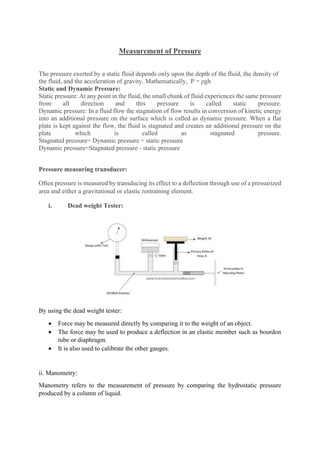
- 1. Measurement of Pressure The pressure exerted by a static fluid depends only upon the depth of the fluid, the density of the fluid, and the acceleration of gravity. Mathematically, P = ρgh Static and Dynamic Pressure: Static pressure: At any point in the fluid, the small chunk of fluid experiences the same pressure from all direction and this pressure is called static pressure. Dynamic pressure: In a fluid flow the stagnation of flow results in conversion of kinetic energy into an additional pressure on the surface which is called as dynamic pressure. When a flat plate is kept against the flow, the fluid is stagnated and creates an additional pressure on the plate which is called as stagnated pressure. Stagnated pressure= Dynamic pressure + static pressure Dynamic pressure=Stagnated pressure - static pressure Pressure measuring transducer: Often pressure is measured by transducing its effect to a deflection through use of a pressurized area and either a gravitational or elastic restraining element. i. Dead weight Tester: By using the dead weight tester: • Force may be measured directly by comparing it to the weight of an object. • The force may be used to produce a deflection in an elastic member such as bourdon tube or diaphragm. • It is also used to calibrate the other gauges. ii. Manometry: Manometry refers to the measurement of pressure by comparing the hydrostatic pressure produced by a column of liquid.
- 2. Manometers are simple, inexpensive and error free instrument found very commonly as pressure measuring device. Its major disadvantage lies in its range and poor in dynamic response. It is not very practical for measuring pressures greater than 100psi. Commonly used manometers are as below: • Well type • Differential or U tube manometer • Inclined tube manometer iii. Pressure transducers: The main types of pressure transducers are a) Bourdon tubes, b) Diaphragms & Capsule type c) bellows . All except diaphragms provide a fairly large displacement that is useful in mechanical gauges and for electrical sensors that require a significant movement. a) Bourdon tube pressure transducer: • Bourdon tube pressure gauges are used for local indication of pressure. • This was first developed by E. Bourdon in 1849. • These can be used to measure the pressure over a wide range from vacuum to high pressure even few thousand PSI. • C type tubes are most common, other shapes are also available such as spiral and helical as shown in fig. Working: • When pressure is applied, the elliptical cross sectional bourdon tube tries to acquire a circular cross section, as a result stress is developed and the tube tries to straighten up. • Thus the free end of the tube moves up, depending on the magnitude of pressure.
- 3. • A deflecting and indicating mechanism is attached to the free end that rotates the pointer and indicates the pressure reading. • The material used is commonly phosphor bronze, brass and beryllium copper. b. Diaphragm type bourdon tube pressure transducer: • The diaphragm pressure transducer are commercially available in two types – metallic and non-metallic. • Metallic diaphragms are known to have good spring characteristics and non-metallic types have no elastic characteristics. Thus, non-metallic types are used rarely, and are usually opposed by a calibrated coil spring or any other elastic type gauge. The non- metallic types are also called slack diaphragm. Working: • The diagram of a diaphragm pressure gauge is shown in figure. When a force acts against a thin stretched diaphragm, it causes a deflection of the diaphragm with its centre deflecting the most. • Since the elastic limit has to be maintained, the deflection of the diaphragm must be kept in a restricted manner. • This can be done by cascading many diaphragm capsules as shown in the figure. • A main capsule is designed by joining two diaphragms at the periphery. • A pressure inlet line is provided at the central position. • When the pressure enters the capsule, the deflection will be the sum of deflections of all the individual capsules. iv. Electrical pressure transducer: • Electrical pressure transducers translate mechanical output into electrical signals. • Electric pressure transducers are preferred over mechanical devices because of their quick response, low hysteresis, better linearity and high accuracy in digital measurement systems. • There are many other pressure gauges developed in recent years to get the pressure as electrical signal. a) Resistance type transducers b) Potentiometer type c) Inductive type
- 4. d) Capacitive type e) Piezoelectric type a) Resistance type transducers: • The basic principle of this kind of transducer is that a variation in the length of the wire causes the change in its electrical resistance. • The most popular transducer from this kind is strain gauge pressure sensor. • A strain gauge is used as secondary element in pressure measurement. • They are joined together with a bellow or diaphragm for effective measurement of pressure. • The figure below shows the arrangement of strain gauge that are mounted on a cantilever spring which is operated by a pair of opposing bellow elements. • When the pressure increases in the bellow, the cantilever gets strained and the strain gauge reads the change in resistance. This is then shown in the display unit in terms of pressure. Similarly strain gauges may also be employed on a flat diaphragm. • Usually, four gauges are mounted as shown in the figure below. • When the pressure increases on the diaphragm, the strain gauges also gets strain and the change in resistance becomes the measure of pressure change. • Now a days strain rosette are available in various sizes which easily picks up the radial strains at the edges and the tangential strains at the centre of a diaphragm. b) Potentiometer type pressure transducer: Devices such as potentiometers and rheostats with sliding wires work on the principle of movable contact or variable resistance type pressure transducers. The closed end of the bourdon tube is connected to the potentiometer wiper. A constant voltage is applied to the end terminals of the potentiometer. The application of pressure to the bourdon tube results in deflection of the closed end. Due to this the wiper moves over the potentiometer varying the resistance of the circuit, thus changing the wiper voltage.
- 5. c) Inductive type Transducer: • The linear variable differential transducer is an inductive type of pressure transducer which works on the principle of mutual inductance. • It transforms a mechanical displacement into an electrical signal. • The magnetic core is connected with the elastic pressure transducer. • The tube senses the pressure and displaces the core. • An LVDT comprises one primary and two secondary coils which are mounted on a common frame. On either sides of the primary coil two secondary coils are placed symmetrically. • A non-contacting magnetic core moves in the centre of these coils. • When the core is in this position, the voltages in the two secondary coils are equal and 1800 out of phase which is taken as zero position. • The displacement of the core from zero position due to the applied pressure increases the induced voltage in one of the secondary coil while the voltage in other decreases. • Due to this the differential voltage, which appears across the two secondary windings is approximately linear for small core displacement and is hence a measure of applied pressure.
- 6. d) Capacitive type pressure transducer: • This works on the principle of capacitance. • Normally this is found in diaphragm type pressure gauge. • This has the advantages like low hysteresis, linearity, repeatability. • It can measure gauge, absolute and differential pressures. • Working: • A variable capacitive transducer comprises a metal diaphragm as the elastic element, which is placed centrally between the two plates. • Initially, when the input pressures are the same, there is no deflection of the diaphragm and hence capacitance remains constant. • Due to the applied pressure, the distance between the fixed plate and the diaphragm varies and hence the capacitance changes. • The resulting change in capacitance can be sensed by a bridge circuit or can be employed to vary the frequency of the oscillator. e) Piezoelectric type pressure transducer: • This is the transducer which works on the principle that when pressure is applied on piezoelectric crystals an electric charge is produced. • A piezoelectric crystal has the capability to generate an electrical potential due to an applied pressure along a preferred axis. • These are simple in construction and less expensive. Working:
- 7. • A piezoelectric pressure transducer comprises a corrugated metal diaphragm on which pressure is applied. • Deflection of diaphragm is transmitted to the piezoelectric crystal through a mechanical link. • The piezoelectric crystal is capable of producing the maximum piezoelectric response in one direction and minimum response in the other direction by accumulating +ve and –vely charged electrons at the surfaces. • Thus the piezoelectric crystal senses the applied pressure and generates a voltage proportional to the applied pressure. • The generated voltage can be measured using a calibrated output voltage measuring instrument, which gives a measure of the applied pressure. MEASUREMENT OF VACUUM: • Pressure below atmosphere is generally termed as low or vacuum pressures. • Measuring low ppressure is little difficult to measure compared to measuring gauge pressure. • Instruments used to measure low pressure are: a) McLeod Gauge b) Pirani Gauge c) Ionisation Gauge d) Knudsen Gauge a) McLeod Gauge: • It works on the fundamental equation of Boyles law. P1V1=P2V2 • Where P and V refers to the pressure and volume respectively and subscripts 1 &2 refers to initial and final conditions. • Conventional McLeod gauge is made of glass. • It consists of the capillary C, bulb B and mercury reservoir which is connected to the lower end of the glass tube such that it can be moved up and down. • The pressure to be measured is connected to the upper end of the glass part.
- 8. • When the mercury level in the gauge is below the cutoff “F”, the unknown pressure fills the gauge including the bulb B and capillary “C”. • When the mercury sump is moved up, the level in the gauge rises and when it reaches the cut off “F” a known volume of gas at pressure to be measured is trapped in bulb B and capillary C. • Mercury is then forced up into the bulb and capillary. • Assume the sump is raised to such a level that the gas at the pressure to be measured which filled the volume above the cut-off is now compressed to the volume represented by the column ‘h’. • Suppose the original volume after the mercury reaches F is V0. Advantages: • It is independent of gas composition. • It serves as a reference standard to calibrate other low pressure gauges. • There is no need of any correction to the mcleod gauge readings. Limitations: • The gas whose pressure is to be measured should obey the Boyles law. • It cannot give a continuous output.
- 9. b) Pirani Gauge: Working Principle: A basic pirani gauge consists of a fine wire of tungsten or platinum of about 0.002 cm in diameter. This wire is mounted in a tube and then connected to the system whose vacuum is to be measured. The temperature range is around (7-400) degree Celsius and the heating current is between (10-100) mA. A bridge circuit is also used for greater accuracy. The pirani gauge is connected as one arm of the bridge circuit. Vacuum measurement is usually taken in three ways. • When the pressure changes, there will be a change in current. For this, the voltage V has to be kept constant. • The resistance R2 of the gauge is measured, by keeping the gauge current constant. • The null balance of the bridge circuit is maintained by adjusting the voltage or current. This change is made with the help of a potentiometer and the change brought will be a measure of the pressure produced. An additional reference gauge can also be used in the adjacent arm of another pirani gauge, in the bridge circuit. The additional gauge is evacuated and sealed, which helps in the compensaton for variation in ambient temperature. For commercial use, the range of the instrument can be extended from 10- 3 Torr to 1 Torr. c) Ionization Gauge: Ionization Gauge is a device that is used to measure vacuum. In the hot cathode type, a column of gas is introduced into which, a potential difference V is applied with free electron in the space. This causes the electron with a charge e to acquire a kinetic energy Ve. If the pressure range of the gas in the column goes below a certain limit, called the critical pressure, then
- 10. corresponding to a voltage larger than the critical voltage Vc, the energy Ve may be high enough to initiate ionization, and positive ions will be produced when the electrons collide with the gas molecules. The value of Vc is smallest for cesium (3.88V) and largest for helium (24.58V), among monoatomic gases or vapours. For diatomic gases like N2, H2 and so on, it is roughly about 15V. This is known as the ionization potential and at this potential the pressure is also important. At very low pressures, during the intervals of time for transit from the cathode to the plate in a vacuum chamber, more than one collision is unlikely for an electron. Then for a fixed accelerating potential V>Vc, the number of positive ions formed would vary linearly with the value of pressure. Thus, a determination of the rate of production of positive ions for a given electron current should give a measure of the pressure. Working: The construction of a hot cathode type ionization gauge consists of a basic vacuum triode. The figure of an external control type hot cathode gauge is shown below. The grid is maintained at a large positive potential with respect to the cathode and the plate. The plate is at a negative potential with respect to the cathode. This method is also known as the external control type ionization gauge as the positive ion collector is external to the electron collector grid with reference to the cathode. The positive ions available between the grid and the cathode will be drawn by the cathode, and those between the grid and the plate will be collected by the plate. The internal control type, the grid is the positive ion collector and the plate is the electron collector.