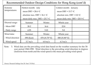
This document provides an overview of load estimation concepts and procedures for calculating cooling and heating loads in buildings. It discusses key topics such as outdoor and indoor design conditions, heat transfer mechanisms, thermal properties of building materials, and common load components from occupants, lighting, equipment, and ventilation. The document also outlines the general process for performing cooling and heating load calculations, including gathering building information, selecting design conditions, calculating space loads, and finding peak design loads. Finally, it provides recommended outdoor design conditions for Hong Kong based on weather data analysis.
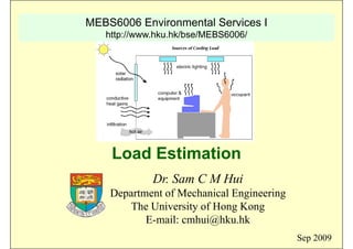
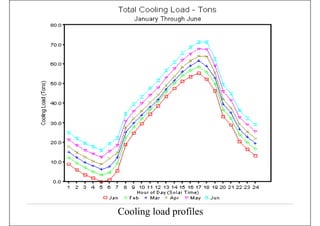


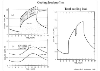
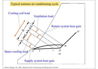
![Cooling Load Principles
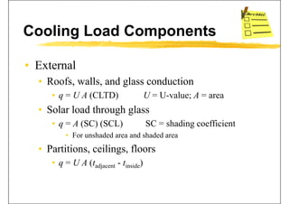
• Space load and equipment loadp q p
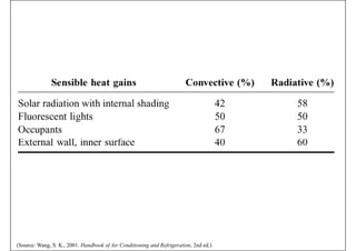
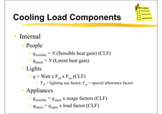
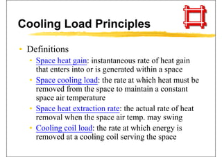
• Space heat gain (sensible, latent, total)
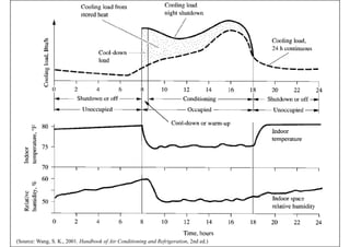
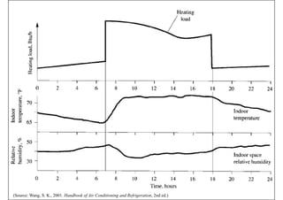
S li / h ti l d [ t b ildi ]• Space cooling / heating load [at building]
• Space heat extraction rate
• Cooling / heating coil load [at air-side system]
• Refrigeration load [at the chiller plant]Refrigeration load [at the chiller plant]
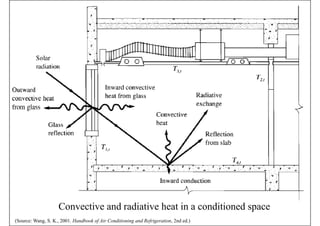
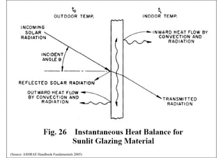
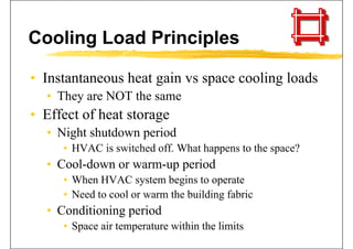
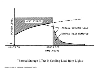
• Instantaneous heat gain
• Convective heat
• Radiative heat (heat absorption)Radiative heat (heat absorption)](https://image.slidesharecdn.com/mebs6006091004-load-150703085649-lva1-app6892/85/Mebs6006-0910-04-load-44-320.jpg)