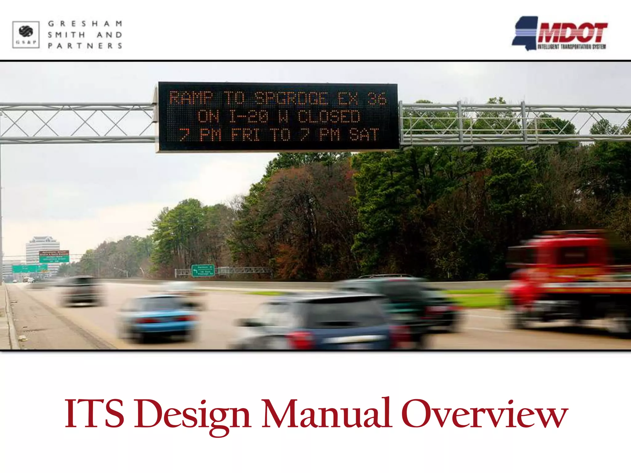
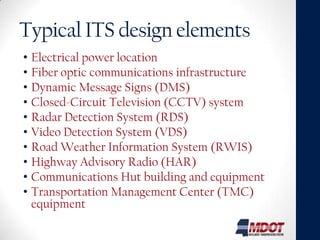
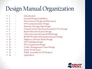
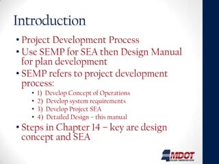
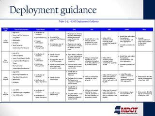
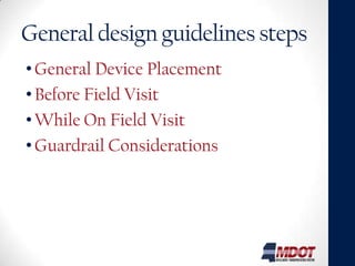
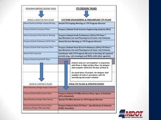
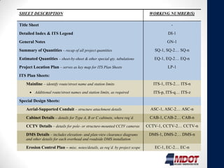
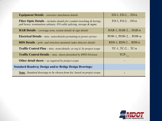
ITS Design Manual Overview
Purpose
• So designers can create concept to
  complete plan set and spec package for
  MDOT ITS projects or other municipal
  ITS projects.
• Uniform guidelines and design criteria for
  ITS elements implemented on MS urban
  freeways, rural freeways, urban arterials
  and rural roadways.
• Manual doesn’t address specific details
  designers encounter, so must confirm
  assumptions with ITS Program Manager.
Typical ITS design elements
• Electrical power location
• Fiber optic communications infrastructure
• Dynamic Message Signs (DMS)
• Closed-Circuit Television (CCTV) system
• Radar Detection System (RDS)
• Video Detection System (VDS)
• Road Weather Information System (RWIS)
• Highway Advisory Radio (HAR)
• Communications Hut building and equipment
• Transportation Management Center (TMC)
  equipment
Design Manual Organization
•   1    –    Introduction
•   2    –    General Design Guidelines
•   3     –   Power Source Design and Placement
•   4    –    ITS Communications Design
•   5    –    Dynamic Message Sign Design
•   6    –    Closed Circuit Television System (CCTV) Design
•   7    –    Radar Detection System Design
•   8    –    Video Detection System (VDS) Design
•   9    –    ROAD Weather Information System Design
•   10   –    Highway Advisory Radio Design
•   11   –    HUT Building Design
•   12   –    HUT Equipment Design
•   13   –    Traffic Management Center Design
•   14   -    Smart Work Zones
•   15   –    PS&E Assembly for ITS Projects
•   16   –    Appendices
Introduction
• Project Development Process
• Use SEMP for SEA then Design Manual
  for plan development
• SEMP refers to project development
  process:
   •   1) Develop Concept of Operations
   •   2) Develop system requirements
   •   3) Develop Project SEA
   •   4) Detailed Design – this manual
• Steps in Chapter 14 – key are design
  concept and SEA
General design guidelines
Provides overall guidance for preliminary
 placement – Details in Sections 3 – 12

• Concept Development
 • Meet w/ District & ITS staff for scope and limits.
 • Research other planned projects and coordinate
   with others
 • Use aerials or plan sheets showing existing
   alignment and can obtain field control for scaling
• Concept Review
Deployment guidance


                      7
General design guidelines steps
• General Device Placement
• Before Field Visit
• While On Field Visit
• Guardrail Considerations
Power Source Design
• Starts in Concept phase
• Early Coordination Required
• What to show on plans
• What are demarcation locations
• When you may need transformer
• Urban vs. Rural area Considerations
• Verify obstacles for routing
ITS Communications Design
• Conduit / Fiber Optic Cable Placement Guidelines
  •   Freeways
  •   Urban Arterials
  •   Rural
  •   Other Agencies
  •   Wireless and Least Broadband
• Field Location Considerations for Fiber / Conduit
  • Cable Pull boxes and Electrical Pull Boxes
• Options
  • Cable Type, Construction, Fiber Mode, Count, Reel to Reel
    Splicing, Conduit Types
• Fiber Allocation
• Communications Design Examples
Fiber Allocation
• Communications Path
• Strategies:
  • Existing vs. New Device Cases; Daisy Chain
  • How Many Drops / Pair
• Which Fibers are Used
• Switch Selection


 ITS Field                              HUT/Control
             Drop Cable   Trunk Cable
  Device                                  Center
Communication Design Examples
                              Typical PTZ Camera
                           Connected to encoder and IP
                                    network
                                     P
                                     T
                                     Z           SP 650


      Composite Cable
              Power
              Data (232/422/485)
              Video


                      Surge Block          Video
                                                                      Encoder
                                           DATA                       SP 662

                                                      Network
                                                       Cable
                                                                      Switch
           Spare Jumper spliced to                                    (A or B)
          Rose and Aqua on Orange                                     SP 658
                 trunk buffer


  Type 5 Pull box
                                         12 count drop cable splice
                                              to orange trunk
                                     Fiber Trunk (72 SM Standard)
ITS Device Design Sections
• Goal / Concept
• Gives Special Provision #, and refers to plan
  sheets / detail sheets that may be required
• Placement Guidelines
 • Urban Freeways
 • Urban Arterial Streets and Highways
 • Rural
• Field Location Considerations
• Additional Sections for additional
  documentation as needed (DMS Types for
  Example)
TMC Design
• Equipment Room Layout
• Equipment Rack Elevations and
  Equipment Interconnections
• Operations Area Layout
• Electrical and Environmental
  Infrastructure
• Construction Coordination
Smart Work Zones
• Guidelines and Process
• Special Provisions
PS&E Assembly
• Includes plans, standard specs, all special provisions,
  NTBs, construction cost estimates, all approved
  agreements with railroads, utilities, and municipalities,
  the proposal assembly and the utility and ROW
  certificates.
• Ch 15 of Roadway Design Manual
• Typical Workflow
• Contract Plans
• Specs
  • Special Provisions
  • NTBs
• Cost Estimates
• ITS-Related Permits & MOAs/MOUs
ROADWAY/BRIDGE DESIGN TASKS                                 ITS DESIGN TASKS


    PHASE A: RIGHT-OF-WAY PLANS              SYSTEMS ENGINEERING & PRELIMINARY ITS PLANS
Attend Roadway/Bridge Scoping Meeting     Attend ITS Scoping Meeting w/ ITS Program Director


Prepare/Submit Conceptual Plans           Prepare/Submit Draft Systems Engineering Analysis (SEA)


Attend Conceptual Plans Review Meeting    Prepare/Submit Draft Preliminary (50%) ITS Plans *,
                                          Specifications List and Planning-Level Const. Cost Estimate
Prepare/Submit Preliminary R.O.W. Plans   Attend Review Meeting w/ ITS Program Director


Prepare/Submit Field Inspection Plans     Prepare/Submit Final SEA & Preliminary (50%) ITS Plans *,
                                          Specifications List and Planning-Level Const. Cost Estimate
Attend Field Inspection                   Coordinate with ITS Program Director to develop all required
                                          permits (e.g., rail crossings) and MOUs with other agencies
Prepare/Submit Final R.O.W. Plans
                                                        If above tasks are not completed in conjunction
                                                        with Phase A: Right-of-Way Plans, the designer
                                                        shall complete within first 90 days of Phase B.

                                                        If a stand-alone ITS project, the designer shall
                                                        complete all tasks in accordance with the
                                                        mutually agreed project schedule.


       PHASE B: CONTRACT PLANS                       FINAL ITS PLANS & SPECIFICATIONS
Attend Roadway/Bridge Design Conference


Prepare/Submit Office Review Plans        Prepare/Submit ITS Office Review Plans, Specs. & Estimate
                                          (95% Submittal)
Attend Roadway/Bridge Office Review       Attend ITS Office Review w/ ITS Program Director


Prepare/Submit Final Contract Plans       Prepare/Submit Final ITS Plans *, Specifications & Estimate
(Roadway/Bridge PS&E Assembly)            (PS&E Assembly)
SHEET DESCRIPTION                                                             WORKING NUMBER(S)

Title Sheet                                                                              -
Detailed Index & ITS Legend                                                            DI-1
General Notes                                                                          GN-1
Summary of Quantities – recap of all project quantities                         SQ-1, SQ-2… SQ-n
Estimated Quantities – sheet-by-sheet & other special qty. tabulations          EQ-1, EQ-2… EQ-n
Project Location Plan – serves as key map for ITS Plan Sheets                          LP-1
ITS Plan Sheets:
    Mainline – identify route/street name and station limits                    ITS-1, ITS-2… ITS-n
         Additional route/street names and station limits, as required          ITS-p, ITS-q… ITS-z
Special Design Sheets:
    Aerial-Supported Conduit – structure attachment details                   ASC-1, ASC-2… ASC-n
    Cabinet Details – details for Type A, B or C cabinets, where req’d.       CAB-1, CAB-2… CAB-n
    CCTV Details – details for pole- or structure-mounted CCTV cameras       CCTV-1, CCTV-2… CCTV-n
    DMS Details – includes elevation- and plan-view clearance diagrams        DMS-1, DMS-2… DMS-n
    and other details for each overhead and roadside DMS installation

    Erosion Control Plan – misc. notes/details, as req’d. by project scope      EC-1, EC-2… EC-n
    Equipment Details – structure attachment details                            ED-1, ED-2… ED-n
    Fiber Optic Details – includes details for conduit trenching & boring;      FO-1, FO-2… FO-n
DMS Details – includes elevation- and plan-view clearance diagrams        DMS-1, DMS-2… DMS-n
   and other details for each overhead and roadside DMS installation

   Erosion Control Plan – misc. notes/details, as req’d. by project scope      EC-1, EC-2… EC-n
   Equipment Details – structure attachment details                            ED-1, ED-2… ED-n
   Fiber Optic Details – includes details for conduit trenching & boring;      FO-1, FO-2… FO-n
   pull boxes; termination cabinets; FO cable splicing, storage & mgmt.

   HAR Details – coverage area, system details & sign details                HAR-1, HAR-2… HAR-n
   Electrical Details – misc. notes/details pertaining to power service      POW-1, POW-2… POW-n
   RDS Details – pole- and structure-mounted radar detector details          RDS-1, RDS-2… RDS-n
   Traffic Control Plan – misc. notes/details, as req’d. by project scope      TC-1, TC-2… TC-n
   Traffic Control Details – misc. sheets furnished by RWD Division                TCP-__
   Other detail sheets – as required by project scope                                 -
Standard Roadway Design and/or Bridge Design Drawings:
   Note: Standard drawings to be chosen from list, based on project scope.            -
Appendices
• A – Plans Checklist – What is needed
  for 50% - 100% Submittals
• B – Model Sheets
• C – Typical Label Formats
• D – Special Provisions (latest at time
  of design manual published version)
• E – Example Notice to Bidder
  Documents

MDOT ITS Design Manual

  • 1.
  • 2.
    Purpose • So designerscan create concept to complete plan set and spec package for MDOT ITS projects or other municipal ITS projects. • Uniform guidelines and design criteria for ITS elements implemented on MS urban freeways, rural freeways, urban arterials and rural roadways. • Manual doesn’t address specific details designers encounter, so must confirm assumptions with ITS Program Manager.
  • 3.
    Typical ITS designelements • Electrical power location • Fiber optic communications infrastructure • Dynamic Message Signs (DMS) • Closed-Circuit Television (CCTV) system • Radar Detection System (RDS) • Video Detection System (VDS) • Road Weather Information System (RWIS) • Highway Advisory Radio (HAR) • Communications Hut building and equipment • Transportation Management Center (TMC) equipment
  • 4.
    Design Manual Organization • 1 – Introduction • 2 – General Design Guidelines • 3 – Power Source Design and Placement • 4 – ITS Communications Design • 5 – Dynamic Message Sign Design • 6 – Closed Circuit Television System (CCTV) Design • 7 – Radar Detection System Design • 8 – Video Detection System (VDS) Design • 9 – ROAD Weather Information System Design • 10 – Highway Advisory Radio Design • 11 – HUT Building Design • 12 – HUT Equipment Design • 13 – Traffic Management Center Design • 14 - Smart Work Zones • 15 – PS&E Assembly for ITS Projects • 16 – Appendices
  • 5.
    Introduction • Project DevelopmentProcess • Use SEMP for SEA then Design Manual for plan development • SEMP refers to project development process: • 1) Develop Concept of Operations • 2) Develop system requirements • 3) Develop Project SEA • 4) Detailed Design – this manual • Steps in Chapter 14 – key are design concept and SEA
  • 6.
    General design guidelines Providesoverall guidance for preliminary placement – Details in Sections 3 – 12 • Concept Development • Meet w/ District & ITS staff for scope and limits. • Research other planned projects and coordinate with others • Use aerials or plan sheets showing existing alignment and can obtain field control for scaling • Concept Review
  • 7.
  • 8.
    General design guidelinessteps • General Device Placement • Before Field Visit • While On Field Visit • Guardrail Considerations
  • 9.
    Power Source Design •Starts in Concept phase • Early Coordination Required • What to show on plans • What are demarcation locations • When you may need transformer • Urban vs. Rural area Considerations • Verify obstacles for routing
  • 10.
    ITS Communications Design •Conduit / Fiber Optic Cable Placement Guidelines • Freeways • Urban Arterials • Rural • Other Agencies • Wireless and Least Broadband • Field Location Considerations for Fiber / Conduit • Cable Pull boxes and Electrical Pull Boxes • Options • Cable Type, Construction, Fiber Mode, Count, Reel to Reel Splicing, Conduit Types • Fiber Allocation • Communications Design Examples
  • 11.
    Fiber Allocation • CommunicationsPath • Strategies: • Existing vs. New Device Cases; Daisy Chain • How Many Drops / Pair • Which Fibers are Used • Switch Selection ITS Field HUT/Control Drop Cable Trunk Cable Device Center
  • 12.
    Communication Design Examples Typical PTZ Camera Connected to encoder and IP network P T Z SP 650 Composite Cable Power Data (232/422/485) Video Surge Block Video Encoder DATA SP 662 Network Cable Switch Spare Jumper spliced to (A or B) Rose and Aqua on Orange SP 658 trunk buffer Type 5 Pull box 12 count drop cable splice to orange trunk Fiber Trunk (72 SM Standard)
  • 13.
    ITS Device DesignSections • Goal / Concept • Gives Special Provision #, and refers to plan sheets / detail sheets that may be required • Placement Guidelines • Urban Freeways • Urban Arterial Streets and Highways • Rural • Field Location Considerations • Additional Sections for additional documentation as needed (DMS Types for Example)
  • 14.
    TMC Design • EquipmentRoom Layout • Equipment Rack Elevations and Equipment Interconnections • Operations Area Layout • Electrical and Environmental Infrastructure • Construction Coordination
  • 15.
    Smart Work Zones •Guidelines and Process • Special Provisions
  • 16.
    PS&E Assembly • Includesplans, standard specs, all special provisions, NTBs, construction cost estimates, all approved agreements with railroads, utilities, and municipalities, the proposal assembly and the utility and ROW certificates. • Ch 15 of Roadway Design Manual • Typical Workflow • Contract Plans • Specs • Special Provisions • NTBs • Cost Estimates • ITS-Related Permits & MOAs/MOUs
  • 17.
    ROADWAY/BRIDGE DESIGN TASKS ITS DESIGN TASKS PHASE A: RIGHT-OF-WAY PLANS SYSTEMS ENGINEERING & PRELIMINARY ITS PLANS Attend Roadway/Bridge Scoping Meeting Attend ITS Scoping Meeting w/ ITS Program Director Prepare/Submit Conceptual Plans Prepare/Submit Draft Systems Engineering Analysis (SEA) Attend Conceptual Plans Review Meeting Prepare/Submit Draft Preliminary (50%) ITS Plans *, Specifications List and Planning-Level Const. Cost Estimate Prepare/Submit Preliminary R.O.W. Plans Attend Review Meeting w/ ITS Program Director Prepare/Submit Field Inspection Plans Prepare/Submit Final SEA & Preliminary (50%) ITS Plans *, Specifications List and Planning-Level Const. Cost Estimate Attend Field Inspection Coordinate with ITS Program Director to develop all required permits (e.g., rail crossings) and MOUs with other agencies Prepare/Submit Final R.O.W. Plans If above tasks are not completed in conjunction with Phase A: Right-of-Way Plans, the designer shall complete within first 90 days of Phase B. If a stand-alone ITS project, the designer shall complete all tasks in accordance with the mutually agreed project schedule. PHASE B: CONTRACT PLANS FINAL ITS PLANS & SPECIFICATIONS Attend Roadway/Bridge Design Conference Prepare/Submit Office Review Plans Prepare/Submit ITS Office Review Plans, Specs. & Estimate (95% Submittal) Attend Roadway/Bridge Office Review Attend ITS Office Review w/ ITS Program Director Prepare/Submit Final Contract Plans Prepare/Submit Final ITS Plans *, Specifications & Estimate (Roadway/Bridge PS&E Assembly) (PS&E Assembly)
  • 18.
    SHEET DESCRIPTION WORKING NUMBER(S) Title Sheet - Detailed Index & ITS Legend DI-1 General Notes GN-1 Summary of Quantities – recap of all project quantities SQ-1, SQ-2… SQ-n Estimated Quantities – sheet-by-sheet & other special qty. tabulations EQ-1, EQ-2… EQ-n Project Location Plan – serves as key map for ITS Plan Sheets LP-1 ITS Plan Sheets: Mainline – identify route/street name and station limits ITS-1, ITS-2… ITS-n Additional route/street names and station limits, as required ITS-p, ITS-q… ITS-z Special Design Sheets: Aerial-Supported Conduit – structure attachment details ASC-1, ASC-2… ASC-n Cabinet Details – details for Type A, B or C cabinets, where req’d. CAB-1, CAB-2… CAB-n CCTV Details – details for pole- or structure-mounted CCTV cameras CCTV-1, CCTV-2… CCTV-n DMS Details – includes elevation- and plan-view clearance diagrams DMS-1, DMS-2… DMS-n and other details for each overhead and roadside DMS installation Erosion Control Plan – misc. notes/details, as req’d. by project scope EC-1, EC-2… EC-n Equipment Details – structure attachment details ED-1, ED-2… ED-n Fiber Optic Details – includes details for conduit trenching & boring; FO-1, FO-2… FO-n
  • 19.
    DMS Details –includes elevation- and plan-view clearance diagrams DMS-1, DMS-2… DMS-n and other details for each overhead and roadside DMS installation Erosion Control Plan – misc. notes/details, as req’d. by project scope EC-1, EC-2… EC-n Equipment Details – structure attachment details ED-1, ED-2… ED-n Fiber Optic Details – includes details for conduit trenching & boring; FO-1, FO-2… FO-n pull boxes; termination cabinets; FO cable splicing, storage & mgmt. HAR Details – coverage area, system details & sign details HAR-1, HAR-2… HAR-n Electrical Details – misc. notes/details pertaining to power service POW-1, POW-2… POW-n RDS Details – pole- and structure-mounted radar detector details RDS-1, RDS-2… RDS-n Traffic Control Plan – misc. notes/details, as req’d. by project scope TC-1, TC-2… TC-n Traffic Control Details – misc. sheets furnished by RWD Division TCP-__ Other detail sheets – as required by project scope - Standard Roadway Design and/or Bridge Design Drawings: Note: Standard drawings to be chosen from list, based on project scope. -
  • 20.
    Appendices • A –Plans Checklist – What is needed for 50% - 100% Submittals • B – Model Sheets • C – Typical Label Formats • D – Special Provisions (latest at time of design manual published version) • E – Example Notice to Bidder Documents

Editor's Notes

  • #9 General Device Placement: Following concept review – conduct field inspectionReview project location, device locations, conduit routing, power sourcesDevice placement criteria:Field conditionsMaintenance accessibilityAbility to route comm to devicesPower accessibilityDevice protection – existing guardrailMotorist protection (addition of guardrail or use of breakaway supports) Before Field Visit:To Do list to optimize data recordingA copy of complete set of plans (base map)Check with District office on any prior roadway plans or aerial photographyContact MDOT Project Manager to arrange access to existing facilitiesWhile on Field Visit:Safety first – high visibility clothingConfirm existing device locations – i.e. poles, cabinets, signs, overhead structures and other fixed roadway features that may be used as a proposed device reference pointNote guardrail length at candidate device locationsDon’t use small signs or guardrail ends as references as they may be damageUse mile markersReference signs and significant interchange signs should be noted and displayed on plans.Guardrail ConsiderationsTry to place devices such that new guardrail not needed. Follow AASHTO Roadside Design Manual and MDOT Roadway Design Manual for guardrail design. Situations that occur on ITS Freeway Projects: Extending Existing GuardrailClosing the gap between two runs of guardrailShortening the guardrail post spacingNew strain pole placed behind existing guardrail – verify existing guardrail meets all current standardsMust consider existing object that is being protected and new support to be installed. The appropriate length needs to be designed both upstream and downstream of the objectsWhen Guardrail is extended the anchor at the end is removed, new guardrail added and new anchor must be installed to current standards.If new guardrail is close to upstream or downstream existing – make judgment on whether closing the gap to create one continuous guardrail is appropriateShortening the post spacing – the offset behind guardrail to pole or object should be 4 ft or more to allow for deflectionIf offset can't be achieved review standards to determine allowable min post spacingIn extreme cases a barrier wall may be required.
  • #10 Coordinate early with power companies on power source locationsWhat to show on plans Power source location and POW routing on plans - Show station for proposed power service locationThis power service location is the Demarc. b/t MDOT and the power company
  • #11 Placement Guidelines give more of an overviewField Location Considerations gives details on spacing, #s, etc. - specific requirements that affect the number and way things are shown on the plan sheets. These sections are included throughout the manual in chapters of the other devices / ITS components
  • #14 Goal / Concept – what the device is for and how it fits in with MDOT operations – information that is helpful to the designer when doing an ITS design. Includes placement Guidelines for the three different area types and additional field location consideration that should be used for placement.
  • #17 Contract Plans Include:Content, Sequencing & NumberingProject IDRevisionsModel SheetsStandard LegendStandard Details
  • #18 Typical Workflow:ITS design may be standalone or incorporated into larger set of plansTypical workflow applicable for standalone ITS projects but also shows how ITS design is integrated into development of MDOT roadway/bridge projects.