SlideShare a Scribd company logo
Strategic Importance of Sawdust Pulping at
Mackenzie
Bauer M & D Digester Technology
R. T. Boughner
General Manager, Mackenzie Operations
March 07, 2000
Revised January 23, 2002; January 30, 2003; March 03, 2004
Bauer M & D Digester Technology
The Bauer M & D digester system was initially developed by Bauer Brothers Company
in the late 1950s. Bauer’s Canadian headquarters was in Brantford, Ontario. The
initial concept was developed by two of Bauer’s staff, H.S. Messing and C.L. Durkee,
after whom the process is named. It is covered under Canadian patents 893,465 and
928,546 and is also patented in the United States, Austria, Finland, Brazil and a
number of other countries.
In a classic ongoing story of merger, acquisition and divestment, Bauer Brothers was
acquired by Combustion Engineering in 1973. In 1989, Combustion Engineering was,
in turn acquired by ASEA Brown Boveri. ABB then decided that the Sprout-Bauer
division, a merger of Bauer Brothers and Sprout-Waldron put together by Combustion
Engineering, did not fit their strategic vision; Sprout-Bauer was sold to Andritz in
1990. As of the late 1990s, the Andritz M & D digester was no longer the only one
available since, due to patent expiry, Ahlstrom, was also offering the M & D. As of
April 2000, however, Andritz is in the process of acquiring Ahlstrom.
Strategic Importance of Sawdust Pulping
As a strategic Pope & Talbot, Inc. corporate capability, we are now producing 108,000
ADt per year of short fibre pulp from sawdust. With no other significant consumer of
sawdust within viable transportation distance, this 220,000 BDU per year of sawdust
had been burned, with subsequent environmental impact, prior to the startup our
sawdust pulping line late in 1996. Our sawdust consumption is supplied from the
Mackenzie sawmills of Canfor Corporation 50%, Abitibi-Consolidated 10-15% with
the remainder coming from Winton Global in Bear Lake 10-12% and Canfor in
Chetwynd 20-25%. Our Andritz-Bauer M & D digester installation consumes the
equivalent of what five beehive incinerators would earlier have incinerated in the
region, and does so with no atmospheric discharge of particulate.
Unloading, Storage and Reclaiming
The short fibre handling and storage system is a series
of conveyors, chutes, reclaims and auxiliary equipment
that transports truck-delivered sawdust and shavings
to the surge bin ahead of the M & D digester. The
system starts at the Megatech drive-through truck
dumper 20-1100 from which the fibre is dumped into
a hopper.
The dumper is an 85-foot tilt-table system designed for
six truckloads per hour at a nominal 20 BDU/load.
Four 4-stage hydraulic cylinders of 11 7/8”, 10 3/8”, 9
1/8” and 7 7/8” cylinder diameter and 40-ft extension
raise the table to a 63-degree incline to permit the
chips to dump by gravity into the receiving hopper.
The hopper is 32 feet long and 22 feet wide at the top
to receive the flow out of the trailer and converges to 34 feet long and 10 feet wide
over the live bottom. It is 17 feet deep at the north end and 8 feet deep at the south
end as the live bottom conveyor 20-1130 is inclined 150 upwards towards the
discharge.
The chain conveyor is 10 feet wide and 33 feet long and is hydraulically driven by a
Hagglunds Marathon MB 400 hydraulic drive. The conveyor discharges onto the #1
unloading conveyor 20-1150.
This #1 belt conveyor is a 40 foot long 48-inch belt conveyor that serves to lift the
fibre stream 9 feet from the low elevation at the drop-off from the bin bottom and lifts
it high enough to dump onto #2 unloading conveyor 20-1160. #2 is another 48-inch
belt unit running perpendicular to the #1 with a 478-foot long run sufficient to lift the
fibre stream 112 feet vertically from below ground to an elevation above the height of
the storage piles.
The transfer point between #2 unloading
conveyor and #3 unloading conveyor is
located in the transfer tower 80 feet above the
ground at the elevation above the top of the
three conical sawdust piles.
The #3 unloading conveyor 20-1180 is a 54-
inch belt that has an initial uphill run but
essentially runs out 352 feet horizontally to
the east, above the three piles. It has three
adjustable plows with “elephant trunk”
telescopic chutes to form the three conical short fibre piles which are centred 75 to
100 feet apart.
Under the sawdust/shavings storage pile are two Andritz-Kone slewing screw
reclaimers 17-1100 and 17-1110, each of which rotates 360° like the hands on a
clock with a 41 foot working radius. The fibre
stream from the reclaims is fed onto #1
infeed belt conveyor 17-1140, a 30-inch belt
which runs 395 feet to the east with a 43 foot
lift and, in turn, discharges under a self
cleaning magnet onto the Acrowood 648 disk-
type scalping screen 17-1150.
With the big chunks removed, the fibre
stream from the scalping screen discharges
onto #2 infeed conveyor 17-1160 , a 48-inch
belt which runs 588 feet to the southeast
with a 127 foot lift and delivers into the top of the Kone surge bin. Due to the long run
it has a counterweight-type tensioning device with a 20-25-ft drop at midlength.
Sawdust Bin 31-1205 and Bin Discharger 31-1210
Sawdust from the 48-inch #2 infeed conveyor
discharges at a transfer point that is 130 feet above the
ground, into the top of the surge bin. The surge bin is
35 feet high and expands in diameter from 10.5 feet at
the top to 13.5 feet at the bottom. The negative taper
minimizes the risk of hang-ups. The bin nominal
capacity of 90 cubic metres or 12 BDU provides 20-25
minutes retention time
Attached to the bottom of the bin is the Andritz-Kone
4-armed HELP bin discharger with double-cylinder
hydraulically drive: 31-1212 and 31-1213. This device
scrapes back and forth across the bottom of the bin to
ensure a constant positive delivery of sawdust to the
metering screw conveyor. The action of the discharger,
which sweeps the entire bottom surface of the bin,
along with the shape of the bin itself, ensures a
uniform plug flow. This minimizes channelling of
sawdust down through the bin. The discharger loosens the compaction at the bottom
level of the bin and permits the sawdust to drop by gravity into the metering screw.
Digester Feed Metering Screw 31-1215
The Andritz-Kone metering screw
is driven by a Hagglunds Viking
UK44-03300 hydraulic drive and
provides accurate metering of
sawdust to the digester and an
initial impregnation with weak
black liquor injected through
nozzles, into the sawdust. The
metering screw is the device that
determines the system production.
The geometrically determined
delivery rate is 3.9 cubic feet per
revolution. Operating speed is about 30 RPM which delivers almost 120 ft3 per
minute, a rate corresponding to 330 unbleached tonnes per day. Variations in screw
pitch allow for the even draw down from the bin and ensure a full volume of this
screw into the metering shroud. At the discharge of the metering shroud, the screw
pitch is doubled to provide an even flow of raw material into the rotary valve.
The original process design had allowed for presteaming provided in the metering
screw by utilizing all of the vented steam from the rotary valve. Flash steam was to
enter the dome of the metering screw, so that any sawdust carried over in the vent
steam is returned to the digester infeed. This was never successful, however, probably
due to the fluffy nature of our “sawdust”. Instead, weak black liquor dilution at 100-
150 usgpm is supplied to the top of the metering screw to improve feeding. The
source of the black liquor is from the D-D washer filtrate tank.
As the screw is filled in the metering shroud, the steam is forced through the
bulkhead into a cavity above the screw. A differential pressure cell is mounted on the
feed end of the metering screw to indicate the pressure in the metering screw. The
presteamer is connected to the rotary valve through a downspout. The downspout is
attached to the rotary valve so that the flow of raw material approaches the valve
nozzle from the small diameter end of the valve.
Inlet Rotary Valve 31-1225
Compared to the more-familiar Kamyr
digester system, the rotary valve, in spite of
the deceptively simple name, performs the
roles of the low pressure feeder, steaming
vessel, high pressure feeder and top
separator. Accomplishing that is a precision
machine that stands 60” high, outlet flange to
inlet flange and weighs 8 tonnes. It has 17
ports, ranging in size from the 42” rotor
insertion port to the two 1” white liquor
injection ports.
The unit is an Andritz-Bauer model 2000 H, driven by a Hagglunds Marathon MA 200
hydraulic drive and designed to transfer sawdust starting from atmospheric pressure
and ending in the high pressure conditions of the main M & D digester vessel and to
preheat the sawdust. The geometrically determined delivery rate is 6.7 cubic feet per
revolution.
The drive end cover plate is 48.75” diameter and the adjusting end cover plate is
39.0” diameter. The rotor tapers from 32” diameter at the back end to 41” diameter at
the front end and measures 27”, along the length of the shaft. The 1:6 ratio of radius
change per axial distance means a 6mm axial shift corresponds to a 1mm change in
radius or 2mm change in diameter. The body is a rugged, thick wall steel casting to
provide dimensional stability throughout the expected range of temperatures and
pressures. The body is overlaid with hardened Inconel 625 steel and also has stellite
on the rotor seat surfaces. This overlay is replaced each time the valve is overhauled
annually.
Viewed from the adjusting end, farthest from
the stairwell, the valve rotates clockwise.
Understanding the operation is helped by
visualizing the ten pockets and
corresponding ten pocket positions. Consider
the orientation with the dividing vane
vertical; positions 1-5 are on the descending
side and positions 6-10 on the rising side.
Sawdust from the metering screw drops
through the 26” inlet port in positions #10
and #1, into the valve rotor which makes a
half rotation and drops the sawdust out
through the 28” outlet port at the #5 and #6
position, down into the main digester vessel. The rotor’s ten pockets successively fill
and empty.
Typical operating speed of the rotary valve is 65% of the metering screw speed so
should be about 20 RPM which delivers about 135 ft3 per minute at a 330 tpd
production rate. This corresponds to about 30 RPM on the metering screw and the
rotary valve volumetric delivery rate is about 115% of that of the metering screw to
provide a “take-away” factor to prevent “backup”.
The steaming vessel function is performed through the injection of recycled steam and
fresh virgin steam in sequence to elevate the pocket pressure from atmospheric to
digester conditions and then back down again through the rotation.
After being filled with sawdust in the #10 and #1 positions, the pocket moves to #2
position where end bell relief recycled steam enters through a 4” diameter connection
to elevate the pressure to 20 psig. Next, in the #3 position, the primary exhaust steam
from the high pressure side comes in through a 4" connection at lowest point of the
pocket to further elevate pressure to 60 psig. Together, these recycled streams
provide the first phase of preheating to digester conditions. The preheating is
completed with three 190 psig steam connections by injection of 10,000-12,000 lb/hr
of fresh steam.
First, through the 2” FCV “A” which generally runs wide open, pre-purge steam comes
into the #4 position from the header through two 1” nozzles that enter radially, one at
each end of the pocket. These channel steam to the bottom of the pocket to aid in
blowing the sticky wetted sawdust out of the pocket and finish elevating pocket
pressure toward digester pressure.
As the pocket reaches the discharge nozzle at the #5 position, the sawdust falls down
into the digester inlet. Nozzle purge steam can be supplied through 4” FCV “C”
through a 6” nozzle, pointing downwards below the #5 position, to keep the discharge
passage down to the digester clear. Generally this is not run since it causes back
pressure and restricts pocket emptying. In the #6 position, emptying is completed by
pocket purge steam supplied through 6” FCV “B” through a 6” nozzle on rising side of
the pocket directed by a turning plenum upward to scour the pocket clear of residual
sawdust. This valve generally runs 45-50% open. As the pocket passes the #7
position, it is cleanly emptied but holding digester pressure which must be vented.
There are two more nozzles, 2” in diameter, located on the 28” diameter bottom
discharge nozzle of the rotary valve. These allow for the direct addition of a portion of
the white liquor charge. The first phase of depressurization occurs in the #8 position
where the primary exhaust port, a 4” nozzle drops the pressure to about 70 psig by
allowing transfer, as noted above, around to the #3 pocket which operates at about 60
psig.
As the pocket moves into the #9 position, the trailing vane is passing the 16”
secondary exhaust port which allows depressurization to 3-5 psig by venting up the
pipe to the sawdust bin for most effective re-use. The pocket then moves into the #10
position at the top where filling begins, to initiate a new cycle. With a 10-pocket rotor
and the rotor at 15 RPM, there are 150 pocket-cycles per minute. The most apparent
indicator of this frequency is the rapid chug-chug-chug pattern as the pockets pass
the secondary exhaust port in the 8 o’clock position.
During operation, small quantities of steam and sawdust blow through the operating
clearance between the rotor and the valve body and on into the end bell cavities of the
rotary valve. This material is exhausted from the end bells through the manifolds to
the previously mentioned 16” diameter connection at the 2 o’clock position and back
into the feed pockets. This relieving of the end bell pressure improves feeding
efficiency and reduces loading on the thrust bearings packing. If the rotor is poorly
seated, the clearance between the rotor and the housing is too great and sawdust
build-up in the end bells further aggravates seating, resulting in excessive steam
blowback up into the metering screw, ultimately stalling it out.
Mackenzie’s species mix is the same blend that makes our MK – 90 chip pulp a global
quality leader: 40% western white spruce, Picea glauca, 40% lodgepole pine, Pinus
contorta and 20% alpine fir, Abies lasiocarpa. But the characteristics of our “sawdust”
furnish are significantly different from typical sawdust. It is 20% green saw kerf and
20% green chip screens undersize fraction; this portion is typical. The other 60% is
planer shavings; lumber is planed after the drying kilns, so this 60% is kiln dried.
The overall feed stream has an average bulk density of 9.25 OD lb/ft3 or 150 kg/m3.
The moisture content ranges 10-30%, very dry by conventional standards.
The general arrangement elevation views of the principal sawdust pulping process
equipment: sawdust bin, M & D digester, surge tube, blow tank, brown stock washer
and auxiliaries are shown in the following views from the east looking west and from
the south looking north.
Bauer Digester Vessel 31-1230
Our M & D digester is a nominal 300 tonne
per day unit, 90 feet long flange to flange,
100 inches diameter for a calculated volume
of 5,175 ft3 and nominal working volume of
3,450 ft3, mounted at the M & D
characteristic 450 angle. It was fabricated by
Nooter Corporation in St. Louis, Missouri in
1996 and is rated for 200 psig and 400 0F. It
is divided into upper and lower halves by the
midfeather. The internal chain conveyor
moves the fibre from the discharge of the
rotary valve down the upper side of the
midfeather to the bottom of the digester and
back up the underside to the outlet to the
surge tube at the top end. It is driven by a
hagglunds Marathon MB 400 hydraulic drive
on the head shaft.
This 450 inclination gives the M & D digester its uniquely characteristic features of the
vapour phase impregnation zone at the inlet as in the Kamyr and Impco designs along
with the positive movement and guaranteed retention time associated with the Black
Clawson Pandia digester. The decantation and vapour phase blow stream is unique to
this design.
The Digester operating pressure of 150 psig is maintained by the injection of 25,000-
35,000 lb/hr of 190 psig steam to the inlet rotary valve. As a pressure vessel, the
digester is designed for a maximum pressure of 200 psig and a maximum
temperature of 400 0F. Digester operating temperature is controlled by the combined
effects of direct injection of 190 psig steam to the digester body and assisted by 8500-
10,000 lb/hr of 80 psig steam to the liquor heater which raise the liquor temperature
to 300 0F. This digester design provides the potential for three distinct temperature
zones: top, mid- and bottom although at Mackenzie we generally run at 350-3600F
throughout. It is particularly critical to maintain a bottom temperature of 355-358 0F.
The chain conveyor speed is adjusted according to production rate and head shaft
rotational speed should be about 2.4% of the metering screw speed. So at a 300 tonne
per day production rate at 28 RPM on the metering screw, the head shaft speed would
be about 0.67 RPM.
The running mechanism consists of two 11.625” diameter steel shafts: head shaft at
the upper end and tail shaft at the lower end. The head shaft is driven by a
Hagglunds Marathom MB 400 hydraulic motor; the tail shaft is an idler with tension
adjustment capability. The upper shaft has a pair of 39” diameter 12-tooth sprockets
mounted on the shaft, centred about 50 inches apart. The lower shaft is attached to a
hemispherical inner head that forms a housing, similar in section to the lower head of
the vessel.
This hemispherical head and lower idler shaft are permitted to move in the inward
direction along the digester axis. The degree of this movement is controlled by a shaft
attached to the idler lower end and extending through the bottom head of the digester
for connection to compression springs. The hemispherical inner head and lower idler
shaft are limited in outward movement to indicate chain wear and keep spring force
at design load. The chain assembly consists of two parallel strands of 20” links, one
running on each pair of upper and lower sprockets.
There is a conveying flight on every third link for a total of 36 flights. The size and
shape can be described as a segment of a 100” diameter circle, cut by a chord 20”
displaced from the diameter, therefore enclosed by 1330 of the circumference. That
makes it approximately 90 inches wide along the chord and 30 inches maximum
height, measured along the radius, chord to circumference. The flights are bent on a
line, parallel to the base and 16” away from the base to provide a 1400 included
angle, making a pocket effect. At a typical chain speed of 0.58 RPM on the head shaft,
the chain will travel at 6 feet per minute, or 10 feet per sprocket revolution, and
the180 foot running length of the chain will make a cycle in 30 minutes. The chain
running length, inlet nozzle to outlet nozzle is 159 feet and with a normal liquor
volume of about 85% of the total vessel volume, the liquor phase cooking time would
be about 25 minutes.
Once retention time is set, K-no control is achieved by adjusting the E.A.:wood ratio.
The main cooking liquor addition is directly to the digester body and a smaller
fraction to the rotary valve. White liquor at about 200 usgpm is diluted with about 25
usgpm of weak black liquor and the combined stream is heated from 145 0F to 280 0F
in the liquor heater before being injected into the upper shell.
Cooking is essentially at constant H-factor; temperature at 355-365 0F or 180-185 0C
and retention time at 20-24 minutes remain constant over the normal range of
production rates.
Thermocompressor 72-4001 and Desuperheater System Operation
Because of its need for steam of
higher pressure and temperature
than other mill applications, the
M & D digester system includes a
Schutte & Koerting model 426
venturi-type thermocompressor
to provide 190 psig steam. The unit is 101 inches overall length and has a 4” inlet for
625 psig steam, 6” inlet for 165 psig steam and a 6” outlet for 190 psig steam.
Physically, it is oriented horizontally and installed along the west side, nearly at the
roof level of the Power Boiler, on the fourth floor level, adjacent to the power boiler
drum and the two deaerator heads. The digester’s consumption rate of up to 35,000
lb/hr is produced by using 10,000 lb/hr of boiler header pressure steam at 625 psig
to elevate the pressure of 25,000 lb/hr of 165 psig high pressure steam. Because of
the proximity of supply of 625 psig steam, the thermocompressor is located in the
Power & Recovery building although it is dedicated to the M & D digester.
Outlet Surge Tube 31-1240
Cooked fibre discharges by gravity from the digester vessel into the surge tube. The
surge tube is nominally 50 feet high and 90 inches in diameter, with a vertically
mounted bottom agitator, 31-1255, providing five minutes retention time at typical
conditions. The stock temperature is reduced from 350 0F at the top inlet to 280 0F at
the bottom outlet by recirculation of about 200 usgpm of weak black liquor filtrate
from the D-D washer first stage filtrate tank. The liquor for both surge tube dilution
and subsequent further dilution in the blow tank is cooled from 185 0F to 125 0F by
circulation through the filtrate cooler before return to the surge tube. The cooling
water from the cooler is at 160 0F and goes to the hot water system.
The stock is then directed to one of two blow lines to the blow tank. There is a
sampling device off the surge tube for stock tests.
Blow Tank 31-1260
The stock enters the flat bottom short fibre blow tank at approximately 5.5%
consistency. The blow tank has an overall height of 70 feet and a nominal volume of
24,000 cubic feet or 180,000 usgal. The main storage section of the blow tank is 26’-
3” feet in diameter and 48 feet high for a nominal capacity of 100 ADt. The bottom of
the blow tank is a 16’-6” foot diameter, 12 feet high dilution zone with side-mounted
agitator, 31-1265.
About 200 usgpm of primary dilution is added to the bottom zone of the tank itself
and another 100 usgpm is added as secondary dilution to the pump suction. This
dilution supply is also cooled in the filtrate cooler. The stock transfer pump, 31-1270
delivers to the Ahlstrom D-D (drum displacer) but this next washing phase of the
operation is beyond the scope of this section.
Blow Heat Cyclone 31-1261 and Vent Condenser 31-1290
The blow tank is equipped with a vent system consisting of a blow heat cyclone and
vent condenser. The cyclone underflow returns by gravity to the blow tank. This
cyclone separates any entrained stock from the gas stream. The “cleaned” vapour
stream then and passes on to the vent condenser which condenses any condensable
gases with the resulting foul condensate pumped to the evaporator seal tank. The
remaining stream of noncondensibles, (NGGs) goes on to the Kamyr relief condenser.
Stock spills in the digester area are collected in the spill recovery sump. They are
then pumped to the clean fibre salvage or to general sewer.
Short Fibre Brown Stock Washing
The heart of the Andritz-Ahlstrom 4040 drum displacer washer 34-1100 is a
rotating drum, 4.00 meters in diameter and 4.00 meters wide. The drum is
driven by two Hagglunds Marathon MB 800 hydraulic drives, one on each end
of the trunnion.
The cylindrical surface has 40 axial compartments, each 4 metres long across
the drum width and about 30 cm wide in the circumferential direction.
Perforated screen plate material forms the bottom of the compartments. There
is no traditional face wire or fabric required on the drum. Under the perforated
plates are the filtrate compartments which are connected to the collection
chambers at the end of the drum. The pulp at 3-9 psig enters the inlet box for
even distribution into the pulp compartments on the drum face. It is then
thickened into a uniform cake that fills each compartment in turn.
Sealing bars separate the feed box from the washing zone and the outlet box.
The sealing bar of the wash zone serves the second function of wiping off the
pulp cake so the compartments are uniformly filled as they enter the wash
zone. The closed pressurized feed box, stable control of feed pressure and
precise thickness of the cake to be washed all combine to achieve very efficient
washing. The discharge sheet consistency ranges from 9-13%.
Our D-D washer is a 3-stage unit. The wash liquor is distributed evenly from
the washer casing at 7-15 psig over each wash zone. During washing, the pulp
and filtrate compartments are hydraulically flooded to ensure air-free sheet
formation and constant speed of displacement of the wash liquor through the
sheet. The surface of the rotating drum has been divided into pockets by ribs
surrounding the drum is a casing to which sealing elements are attached.
Sealing elements separate different washing zones and are connected to the
ribs. The feed zone extends from the 6:30 o’clock position to the 8:00 o’clock
position; the first washing stage from 8:00 o’clock to 10:30; the second
washing stage from 10:30 to 1:00 o’clock; the third washing stage from 1:00 to
4:00 o’clock; the thickening zone from 4:00 to 6:00 o’clock and the pulp outlet
at the 6:30 position.
The distribution valve connects the drum channels and filtrate circulation pipes
for filtrate removal and counter-current washing. The distribution valve,
located at one end of the drum, has been divided into sectors corresponding to
the washing stages so the filtrates are not mixed. Filtrate from the thickening
zone and from the first washing stage zone are discharged through two
separate droplegs into the D-D washer filtrate tank 34-1150. It is 18’-0” in
diameter and 21’-6” high, a nominal 32,000 usg tank with an internal seal well
to submerge the discharge from each downleg. Weak black liquor from this
tank is pumped to the main storage tanks, 60-1001 and 60-1002.
The D-D washer can have 1 to 4 washing zones, depending on the application.
Our washer has 3 washing zones. In addition, the washer has a feed zone and
a discharge zone. Pulp is removed below the discharge zone by a discharge
screw.
The pulp is pumped to the feed zone at a pressure of 1.5 - 7.0 psig and at a
consistency of 4.0 - 4.5 %. The pressurized pulp is thickened on the surface of
the perforated plate of the drum and fills the pockets separated by the ribs.
Concurrently the filtrate passes the perforated plate.
When the pocket filled with pulp passes the first sealing element, excess pulp
is wiped off keeping the thickness of the pulp cake constant. The feed pressure
is controlled along with the feed consistency. This results in the porosity of the
pulp cake being uniform. This gives the optimum washing result at each
operating rate.
The pulp cake entering the first washing zone is of uniform thickness and
porosity and at 10 - 12 % consistency. As the drum rotates, 3 displacement
washings are carried out using the counter-current washing principle. The
dirtier liquor present in the pulp cake in the previous stage is displaced by the
filtrate of the cleaner stage. Then the filtrate is fed to the previous dirtier stage
as washing liquid.
Filtrate from the decker filtrate tank is used as washing liquid in the third
washing stage. The maximum pressure of the wash water is 14.5 psig. The
pressure of the wash filtrate is increased somewhat by circulating filtrate
pumps located between the washing stages.
The complete washing and filtrate circulation is pressurized by the wash water
pressure and intermediate filtrate pumps. This prevents the air from mixing
with the pulp.
From the last washing stage the pulp enters the discharge stage. When the
cake is by the last sealing element, a connection opens from the filtrate channel
to the vacuum pump which increases cake consistency by drawing the filtrate
from below the perforated plate. After the cake has passed the suction point, a
short pressurized air impulse is introduced below the perforated plate. This air
impulse loosens the cake so the pulp falls onto the discharge screw.
After the pulp has been discharged, the perforated plate of the drum is washed
by the wash water showers. The perforated plate shower pump increases the
shower water pressure to 116-145 psig.
Washing of the perforated plate can occasionally be made more effective by the
supplying the showers through the high-pressure wash pipe, e.g. with wash
intervals of 5 min. The maximum allowable wash water pressure in the pipe is
1450 psig.
Conclusion
Our M & D digester based sawdust pulping system has been an extremely
successful addition to the Mackenzie facility. Higher temperature-pressure and
higher alkali:wood charge makes the M & D digester a high-intensity cooking
machine! An M & D digester doesn’t have to “look big” to “produce big”.
Volumetric productivity is 4-5 times that of a Kamyr or batch system…~60 tpd
per 1,000 ft3 compared to ~15 tpd per 1,000 ft3.
Tom Boughner
Mill Manager, Pulp Operations
Norske Skog Mackenzie
September 20, 2000

More Related Content

What's hot

3 A Papermachine Steam Systems Part1
3 A Papermachine Steam Systems Part13 A Papermachine Steam Systems Part1
3 A Papermachine Steam Systems Part1Nhan Vo Trong
 
Sizing in Fabric Manufacturing
Sizing in Fabric ManufacturingSizing in Fabric Manufacturing
Sizing in Fabric Manufacturing
atanu4607
 
COAL HANDLING PLANT
COAL  HANDLING PLANTCOAL  HANDLING PLANT
COAL HANDLING PLANT
pulak126
 
Coal and Ash Handling Power Plant Engineering
Coal and Ash Handling Power Plant EngineeringCoal and Ash Handling Power Plant Engineering
Coal and Ash Handling Power Plant Engineering
Ajaypalsinh Barad
 
Ash handling plants of Thermal Power Stations
Ash handling plants of Thermal Power StationsAsh handling plants of Thermal Power Stations
Ash handling plants of Thermal Power Stations
Manohar Tatwawadi
 
Cement industry : grinding process of ball mill
Cement industry : grinding process of ball millCement industry : grinding process of ball mill
Cement industry : grinding process of ball mill
Pankaj Verma
 
3b Paper Machine Steam Systems Part2
3b Paper Machine Steam Systems Part23b Paper Machine Steam Systems Part2
3b Paper Machine Steam Systems Part2Nhan Vo Trong
 
Coarse cleaner and fine cleaner presentation.
Coarse cleaner and fine cleaner presentation.Coarse cleaner and fine cleaner presentation.
Coarse cleaner and fine cleaner presentation.
KATHAMAHANTY
 
classifications and working of mills in a power plant
classifications and working of mills in a power plantclassifications and working of mills in a power plant
classifications and working of mills in a power plant
VVDVARAPRASAD
 
Roll crushers
Roll crushers Roll crushers
Roll crushers
Naveen Choudhary
 
Warping and details
Warping and detailsWarping and details
Warping and details
Mahbubay Rabbani Mim
 
Suggestive Improvements in Yankee Internal Design
Suggestive Improvements in Yankee Internal DesignSuggestive Improvements in Yankee Internal Design
Suggestive Improvements in Yankee Internal Design
Devesh Singhal
 
Tyer cord
Tyer cordTyer cord
analysis of Modern loom (Type, Brand, specification)
analysis of Modern loom (Type, Brand, specification)analysis of Modern loom (Type, Brand, specification)
analysis of Modern loom (Type, Brand, specification)
Rajib Mia
 
picking mechanism of shuttle
picking mechanism of shuttlepicking mechanism of shuttle
picking mechanism of shuttle
Nahar spinning mills bhopal
 
Fully automatic cotton ginning machine : cotton ginnery
Fully automatic cotton ginning machine : cotton ginneryFully automatic cotton ginning machine : cotton ginnery
Fully automatic cotton ginning machine : cotton ginnery
PRAMUKH STEEL INDUSTRIES
 
Pumps
PumpsPumps

What's hot (20)

3 A Papermachine Steam Systems Part1
3 A Papermachine Steam Systems Part13 A Papermachine Steam Systems Part1
3 A Papermachine Steam Systems Part1
 
Sizing in Fabric Manufacturing
Sizing in Fabric ManufacturingSizing in Fabric Manufacturing
Sizing in Fabric Manufacturing
 
COAL HANDLING PLANT
COAL  HANDLING PLANTCOAL  HANDLING PLANT
COAL HANDLING PLANT
 
Coal and Ash Handling Power Plant Engineering
Coal and Ash Handling Power Plant EngineeringCoal and Ash Handling Power Plant Engineering
Coal and Ash Handling Power Plant Engineering
 
Ash handling plants of Thermal Power Stations
Ash handling plants of Thermal Power StationsAsh handling plants of Thermal Power Stations
Ash handling plants of Thermal Power Stations
 
Cement industry : grinding process of ball mill
Cement industry : grinding process of ball millCement industry : grinding process of ball mill
Cement industry : grinding process of ball mill
 
3b Paper Machine Steam Systems Part2
3b Paper Machine Steam Systems Part23b Paper Machine Steam Systems Part2
3b Paper Machine Steam Systems Part2
 
Coarse cleaner and fine cleaner presentation.
Coarse cleaner and fine cleaner presentation.Coarse cleaner and fine cleaner presentation.
Coarse cleaner and fine cleaner presentation.
 
classifications and working of mills in a power plant
classifications and working of mills in a power plantclassifications and working of mills in a power plant
classifications and working of mills in a power plant
 
Roll crushers
Roll crushers Roll crushers
Roll crushers
 
Warping and details
Warping and detailsWarping and details
Warping and details
 
Turbo generator & its auxiliaries
Turbo generator & its auxiliariesTurbo generator & its auxiliaries
Turbo generator & its auxiliaries
 
Suggestive Improvements in Yankee Internal Design
Suggestive Improvements in Yankee Internal DesignSuggestive Improvements in Yankee Internal Design
Suggestive Improvements in Yankee Internal Design
 
Tyer cord
Tyer cordTyer cord
Tyer cord
 
analysis of Modern loom (Type, Brand, specification)
analysis of Modern loom (Type, Brand, specification)analysis of Modern loom (Type, Brand, specification)
analysis of Modern loom (Type, Brand, specification)
 
Bicomponent fibers
Bicomponent fibersBicomponent fibers
Bicomponent fibers
 
picking mechanism of shuttle
picking mechanism of shuttlepicking mechanism of shuttle
picking mechanism of shuttle
 
Fully automatic cotton ginning machine : cotton ginnery
Fully automatic cotton ginning machine : cotton ginneryFully automatic cotton ginning machine : cotton ginnery
Fully automatic cotton ginning machine : cotton ginnery
 
Pumps
PumpsPumps
Pumps
 
Blowroom
BlowroomBlowroom
Blowroom
 

Similar to Mc kenzie paper 112 2012

Specifications of double drum asphalt plant – atlas technologies
Specifications of double drum asphalt plant – atlas technologiesSpecifications of double drum asphalt plant – atlas technologies
Specifications of double drum asphalt plant – atlas technologies
Atlas Technologies
 
Specifications of Counter Flow Asphalt Plant - Atlas Technologies
Specifications of Counter Flow Asphalt Plant - Atlas TechnologiesSpecifications of Counter Flow Asphalt Plant - Atlas Technologies
Specifications of Counter Flow Asphalt Plant - Atlas Technologies
Atlas Technologies
 
Specifications Of Asphalt Mix Plant - Atlas Technologies
Specifications Of Asphalt Mix Plant - Atlas TechnologiesSpecifications Of Asphalt Mix Plant - Atlas Technologies
Specifications Of Asphalt Mix Plant - Atlas Technologies
Atlas Technologies
 
Specifications mobile asphalt mix plant - Atlas Technologies
Specifications mobile asphalt mix plant - Atlas TechnologiesSpecifications mobile asphalt mix plant - Atlas Technologies
Specifications mobile asphalt mix plant - Atlas Technologies
Atlas Technologies
 
Comfortable KODigital cwmf portables plant
Comfortable KODigital cwmf portables plantComfortable KODigital cwmf portables plant
Comfortable KODigital cwmf portables plant
kobelco2567
 
Specifications of double drum asphalt plant – atlas industries
Specifications of double drum asphalt plant – atlas industriesSpecifications of double drum asphalt plant – atlas industries
Specifications of double drum asphalt plant – atlas industries
atlasindustries
 
Specifications double drum plant export
Specifications double drum plant   exportSpecifications double drum plant   export
Specifications double drum plant export
Atlas Industries
 
Specifications of asphalt drum mix plant - atlas industries
Specifications of asphalt drum mix plant  - atlas industriesSpecifications of asphalt drum mix plant  - atlas industries
Specifications of asphalt drum mix plant - atlas industries
atlasindustries
 
Specifications Of Portable Asphalt Drum Mix Plant - Atlas Industries
Specifications Of Portable Asphalt Drum Mix Plant - Atlas IndustriesSpecifications Of Portable Asphalt Drum Mix Plant - Atlas Industries
Specifications Of Portable Asphalt Drum Mix Plant - Atlas Industries
atlasindustries
 
Specifications drum mix plant domestic
Specifications drum mix plant   domesticSpecifications drum mix plant   domestic
Specifications drum mix plant domestic
Atlas Industries
 
Feed Mill Operations.pptx
Feed Mill Operations.pptxFeed Mill Operations.pptx
Feed Mill Operations.pptx
Dr Ameer Suhail
 
Specifications Double Drum Asphalt Plant by Atlas Industries
Specifications Double Drum Asphalt Plant by Atlas IndustriesSpecifications Double Drum Asphalt Plant by Atlas Industries
Specifications Double Drum Asphalt Plant by Atlas Industries
Atlas Industries
 
Storage project - Grain handling equipment upgrades at Strawson’s Farms
Storage project - Grain handling equipment upgrades at Strawson’s FarmsStorage project - Grain handling equipment upgrades at Strawson’s Farms
Storage project - Grain handling equipment upgrades at Strawson’s Farms
Milling and Grain magazine
 
Wet mix macadam plant manufacturer and exporter – atlas technologies
Wet mix macadam plant manufacturer and exporter – atlas technologiesWet mix macadam plant manufacturer and exporter – atlas technologies
Wet mix macadam plant manufacturer and exporter – atlas technologies
Atlas Technologies
 
CASE STUDY: Smart Elbow® installation at Miller Brewing
CASE STUDY: Smart Elbow® installation at Miller BrewingCASE STUDY: Smart Elbow® installation at Miller Brewing
CASE STUDY: Smart Elbow® installation at Miller Brewing
Milling and Grain magazine
 
Compliance Tools on Wheels
Compliance Tools on WheelsCompliance Tools on Wheels
Compliance Tools on Wheels
Don Talend
 
International Journal on Emerging Technologies (Special Issue
International Journal on Emerging Technologies (Special Issue International Journal on Emerging Technologies (Special Issue
International Journal on Emerging Technologies (Special Issue
hildredzr1di
 
Road Construction Exporter – Atlas Industries
Road Construction Exporter – Atlas IndustriesRoad Construction Exporter – Atlas Industries
Road Construction Exporter – Atlas Industries
Atlas Industries
 
Erection guidelinesfor500mw boilerpressureparts
Erection guidelinesfor500mw boilerpressurepartsErection guidelinesfor500mw boilerpressureparts
Erection guidelinesfor500mw boilerpressureparts
Vijay Raj
 

Similar to Mc kenzie paper 112 2012 (20)

Specifications of double drum asphalt plant – atlas technologies
Specifications of double drum asphalt plant – atlas technologiesSpecifications of double drum asphalt plant – atlas technologies
Specifications of double drum asphalt plant – atlas technologies
 
Specifications of Counter Flow Asphalt Plant - Atlas Technologies
Specifications of Counter Flow Asphalt Plant - Atlas TechnologiesSpecifications of Counter Flow Asphalt Plant - Atlas Technologies
Specifications of Counter Flow Asphalt Plant - Atlas Technologies
 
Specifications Of Asphalt Mix Plant - Atlas Technologies
Specifications Of Asphalt Mix Plant - Atlas TechnologiesSpecifications Of Asphalt Mix Plant - Atlas Technologies
Specifications Of Asphalt Mix Plant - Atlas Technologies
 
Specifications mobile asphalt mix plant - Atlas Technologies
Specifications mobile asphalt mix plant - Atlas TechnologiesSpecifications mobile asphalt mix plant - Atlas Technologies
Specifications mobile asphalt mix plant - Atlas Technologies
 
Comfortable KODigital cwmf portables plant
Comfortable KODigital cwmf portables plantComfortable KODigital cwmf portables plant
Comfortable KODigital cwmf portables plant
 
Specifications of double drum asphalt plant – atlas industries
Specifications of double drum asphalt plant – atlas industriesSpecifications of double drum asphalt plant – atlas industries
Specifications of double drum asphalt plant – atlas industries
 
Specifications double drum plant export
Specifications double drum plant   exportSpecifications double drum plant   export
Specifications double drum plant export
 
Specifications of asphalt drum mix plant - atlas industries
Specifications of asphalt drum mix plant  - atlas industriesSpecifications of asphalt drum mix plant  - atlas industries
Specifications of asphalt drum mix plant - atlas industries
 
Specifications Of Portable Asphalt Drum Mix Plant - Atlas Industries
Specifications Of Portable Asphalt Drum Mix Plant - Atlas IndustriesSpecifications Of Portable Asphalt Drum Mix Plant - Atlas Industries
Specifications Of Portable Asphalt Drum Mix Plant - Atlas Industries
 
Specifications drum mix plant domestic
Specifications drum mix plant   domesticSpecifications drum mix plant   domestic
Specifications drum mix plant domestic
 
Feed Mill Operations.pptx
Feed Mill Operations.pptxFeed Mill Operations.pptx
Feed Mill Operations.pptx
 
Specifications Double Drum Asphalt Plant by Atlas Industries
Specifications Double Drum Asphalt Plant by Atlas IndustriesSpecifications Double Drum Asphalt Plant by Atlas Industries
Specifications Double Drum Asphalt Plant by Atlas Industries
 
Storage project - Grain handling equipment upgrades at Strawson’s Farms
Storage project - Grain handling equipment upgrades at Strawson’s FarmsStorage project - Grain handling equipment upgrades at Strawson’s Farms
Storage project - Grain handling equipment upgrades at Strawson’s Farms
 
Wet mix macadam plant manufacturer and exporter – atlas technologies
Wet mix macadam plant manufacturer and exporter – atlas technologiesWet mix macadam plant manufacturer and exporter – atlas technologies
Wet mix macadam plant manufacturer and exporter – atlas technologies
 
AnFeng HSM
AnFeng HSMAnFeng HSM
AnFeng HSM
 
CASE STUDY: Smart Elbow® installation at Miller Brewing
CASE STUDY: Smart Elbow® installation at Miller BrewingCASE STUDY: Smart Elbow® installation at Miller Brewing
CASE STUDY: Smart Elbow® installation at Miller Brewing
 
Compliance Tools on Wheels
Compliance Tools on WheelsCompliance Tools on Wheels
Compliance Tools on Wheels
 
International Journal on Emerging Technologies (Special Issue
International Journal on Emerging Technologies (Special Issue International Journal on Emerging Technologies (Special Issue
International Journal on Emerging Technologies (Special Issue
 
Road Construction Exporter – Atlas Industries
Road Construction Exporter – Atlas IndustriesRoad Construction Exporter – Atlas Industries
Road Construction Exporter – Atlas Industries
 
Erection guidelinesfor500mw boilerpressureparts
Erection guidelinesfor500mw boilerpressurepartsErection guidelinesfor500mw boilerpressureparts
Erection guidelinesfor500mw boilerpressureparts
 

Recently uploaded

block diagram and signal flow graph representation
block diagram and signal flow graph representationblock diagram and signal flow graph representation
block diagram and signal flow graph representation
Divya Somashekar
 
Industrial Training at Shahjalal Fertilizer Company Limited (SFCL)
Industrial Training at Shahjalal Fertilizer Company Limited (SFCL)Industrial Training at Shahjalal Fertilizer Company Limited (SFCL)
Industrial Training at Shahjalal Fertilizer Company Limited (SFCL)
MdTanvirMahtab2
 
Student information management system project report ii.pdf
Student information management system project report ii.pdfStudent information management system project report ii.pdf
Student information management system project report ii.pdf
Kamal Acharya
 
ethical hacking-mobile hacking methods.ppt
ethical hacking-mobile hacking methods.pptethical hacking-mobile hacking methods.ppt
ethical hacking-mobile hacking methods.ppt
Jayaprasanna4
 
Railway Signalling Principles Edition 3.pdf
Railway Signalling Principles Edition 3.pdfRailway Signalling Principles Edition 3.pdf
Railway Signalling Principles Edition 3.pdf
TeeVichai
 
WATER CRISIS and its solutions-pptx 1234
WATER CRISIS and its solutions-pptx 1234WATER CRISIS and its solutions-pptx 1234
WATER CRISIS and its solutions-pptx 1234
AafreenAbuthahir2
 
power quality voltage fluctuation UNIT - I.pptx
power quality voltage fluctuation UNIT - I.pptxpower quality voltage fluctuation UNIT - I.pptx
power quality voltage fluctuation UNIT - I.pptx
ViniHema
 
Runway Orientation Based on the Wind Rose Diagram.pptx
Runway Orientation Based on the Wind Rose Diagram.pptxRunway Orientation Based on the Wind Rose Diagram.pptx
Runway Orientation Based on the Wind Rose Diagram.pptx
SupreethSP4
 
ethical hacking in wireless-hacking1.ppt
ethical hacking in wireless-hacking1.pptethical hacking in wireless-hacking1.ppt
ethical hacking in wireless-hacking1.ppt
Jayaprasanna4
 
Architectural Portfolio Sean Lockwood
Architectural Portfolio Sean LockwoodArchitectural Portfolio Sean Lockwood
Architectural Portfolio Sean Lockwood
seandesed
 
一比一原版(IIT毕业证)伊利诺伊理工大学毕业证成绩单专业办理
一比一原版(IIT毕业证)伊利诺伊理工大学毕业证成绩单专业办理一比一原版(IIT毕业证)伊利诺伊理工大学毕业证成绩单专业办理
一比一原版(IIT毕业证)伊利诺伊理工大学毕业证成绩单专业办理
zwunae
 
Pile Foundation by Venkatesh Taduvai (Sub Geotechnical Engineering II)-conver...
Pile Foundation by Venkatesh Taduvai (Sub Geotechnical Engineering II)-conver...Pile Foundation by Venkatesh Taduvai (Sub Geotechnical Engineering II)-conver...
Pile Foundation by Venkatesh Taduvai (Sub Geotechnical Engineering II)-conver...
AJAYKUMARPUND1
 
CFD Simulation of By-pass Flow in a HRSG module by R&R Consult.pptx
CFD Simulation of By-pass Flow in a HRSG module by R&R Consult.pptxCFD Simulation of By-pass Flow in a HRSG module by R&R Consult.pptx
CFD Simulation of By-pass Flow in a HRSG module by R&R Consult.pptx
R&R Consult
 
H.Seo, ICLR 2024, MLILAB, KAIST AI.pdf
H.Seo,  ICLR 2024, MLILAB,  KAIST AI.pdfH.Seo,  ICLR 2024, MLILAB,  KAIST AI.pdf
H.Seo, ICLR 2024, MLILAB, KAIST AI.pdf
MLILAB
 
一比一原版(SFU毕业证)西蒙菲莎大学毕业证成绩单如何办理
一比一原版(SFU毕业证)西蒙菲莎大学毕业证成绩单如何办理一比一原版(SFU毕业证)西蒙菲莎大学毕业证成绩单如何办理
一比一原版(SFU毕业证)西蒙菲莎大学毕业证成绩单如何办理
bakpo1
 
RAT: Retrieval Augmented Thoughts Elicit Context-Aware Reasoning in Long-Hori...
RAT: Retrieval Augmented Thoughts Elicit Context-Aware Reasoning in Long-Hori...RAT: Retrieval Augmented Thoughts Elicit Context-Aware Reasoning in Long-Hori...
RAT: Retrieval Augmented Thoughts Elicit Context-Aware Reasoning in Long-Hori...
thanhdowork
 
NO1 Uk best vashikaran specialist in delhi vashikaran baba near me online vas...
NO1 Uk best vashikaran specialist in delhi vashikaran baba near me online vas...NO1 Uk best vashikaran specialist in delhi vashikaran baba near me online vas...
NO1 Uk best vashikaran specialist in delhi vashikaran baba near me online vas...
Amil Baba Dawood bangali
 
Planning Of Procurement o different goods and services
Planning Of Procurement o different goods and servicesPlanning Of Procurement o different goods and services
Planning Of Procurement o different goods and services
JoytuBarua2
 
Immunizing Image Classifiers Against Localized Adversary Attacks
Immunizing Image Classifiers Against Localized Adversary AttacksImmunizing Image Classifiers Against Localized Adversary Attacks
Immunizing Image Classifiers Against Localized Adversary Attacks
gerogepatton
 
The Benefits and Techniques of Trenchless Pipe Repair.pdf
The Benefits and Techniques of Trenchless Pipe Repair.pdfThe Benefits and Techniques of Trenchless Pipe Repair.pdf
The Benefits and Techniques of Trenchless Pipe Repair.pdf
Pipe Restoration Solutions
 

Recently uploaded (20)

block diagram and signal flow graph representation
block diagram and signal flow graph representationblock diagram and signal flow graph representation
block diagram and signal flow graph representation
 
Industrial Training at Shahjalal Fertilizer Company Limited (SFCL)
Industrial Training at Shahjalal Fertilizer Company Limited (SFCL)Industrial Training at Shahjalal Fertilizer Company Limited (SFCL)
Industrial Training at Shahjalal Fertilizer Company Limited (SFCL)
 
Student information management system project report ii.pdf
Student information management system project report ii.pdfStudent information management system project report ii.pdf
Student information management system project report ii.pdf
 
ethical hacking-mobile hacking methods.ppt
ethical hacking-mobile hacking methods.pptethical hacking-mobile hacking methods.ppt
ethical hacking-mobile hacking methods.ppt
 
Railway Signalling Principles Edition 3.pdf
Railway Signalling Principles Edition 3.pdfRailway Signalling Principles Edition 3.pdf
Railway Signalling Principles Edition 3.pdf
 
WATER CRISIS and its solutions-pptx 1234
WATER CRISIS and its solutions-pptx 1234WATER CRISIS and its solutions-pptx 1234
WATER CRISIS and its solutions-pptx 1234
 
power quality voltage fluctuation UNIT - I.pptx
power quality voltage fluctuation UNIT - I.pptxpower quality voltage fluctuation UNIT - I.pptx
power quality voltage fluctuation UNIT - I.pptx
 
Runway Orientation Based on the Wind Rose Diagram.pptx
Runway Orientation Based on the Wind Rose Diagram.pptxRunway Orientation Based on the Wind Rose Diagram.pptx
Runway Orientation Based on the Wind Rose Diagram.pptx
 
ethical hacking in wireless-hacking1.ppt
ethical hacking in wireless-hacking1.pptethical hacking in wireless-hacking1.ppt
ethical hacking in wireless-hacking1.ppt
 
Architectural Portfolio Sean Lockwood
Architectural Portfolio Sean LockwoodArchitectural Portfolio Sean Lockwood
Architectural Portfolio Sean Lockwood
 
一比一原版(IIT毕业证)伊利诺伊理工大学毕业证成绩单专业办理
一比一原版(IIT毕业证)伊利诺伊理工大学毕业证成绩单专业办理一比一原版(IIT毕业证)伊利诺伊理工大学毕业证成绩单专业办理
一比一原版(IIT毕业证)伊利诺伊理工大学毕业证成绩单专业办理
 
Pile Foundation by Venkatesh Taduvai (Sub Geotechnical Engineering II)-conver...
Pile Foundation by Venkatesh Taduvai (Sub Geotechnical Engineering II)-conver...Pile Foundation by Venkatesh Taduvai (Sub Geotechnical Engineering II)-conver...
Pile Foundation by Venkatesh Taduvai (Sub Geotechnical Engineering II)-conver...
 
CFD Simulation of By-pass Flow in a HRSG module by R&R Consult.pptx
CFD Simulation of By-pass Flow in a HRSG module by R&R Consult.pptxCFD Simulation of By-pass Flow in a HRSG module by R&R Consult.pptx
CFD Simulation of By-pass Flow in a HRSG module by R&R Consult.pptx
 
H.Seo, ICLR 2024, MLILAB, KAIST AI.pdf
H.Seo,  ICLR 2024, MLILAB,  KAIST AI.pdfH.Seo,  ICLR 2024, MLILAB,  KAIST AI.pdf
H.Seo, ICLR 2024, MLILAB, KAIST AI.pdf
 
一比一原版(SFU毕业证)西蒙菲莎大学毕业证成绩单如何办理
一比一原版(SFU毕业证)西蒙菲莎大学毕业证成绩单如何办理一比一原版(SFU毕业证)西蒙菲莎大学毕业证成绩单如何办理
一比一原版(SFU毕业证)西蒙菲莎大学毕业证成绩单如何办理
 
RAT: Retrieval Augmented Thoughts Elicit Context-Aware Reasoning in Long-Hori...
RAT: Retrieval Augmented Thoughts Elicit Context-Aware Reasoning in Long-Hori...RAT: Retrieval Augmented Thoughts Elicit Context-Aware Reasoning in Long-Hori...
RAT: Retrieval Augmented Thoughts Elicit Context-Aware Reasoning in Long-Hori...
 
NO1 Uk best vashikaran specialist in delhi vashikaran baba near me online vas...
NO1 Uk best vashikaran specialist in delhi vashikaran baba near me online vas...NO1 Uk best vashikaran specialist in delhi vashikaran baba near me online vas...
NO1 Uk best vashikaran specialist in delhi vashikaran baba near me online vas...
 
Planning Of Procurement o different goods and services
Planning Of Procurement o different goods and servicesPlanning Of Procurement o different goods and services
Planning Of Procurement o different goods and services
 
Immunizing Image Classifiers Against Localized Adversary Attacks
Immunizing Image Classifiers Against Localized Adversary AttacksImmunizing Image Classifiers Against Localized Adversary Attacks
Immunizing Image Classifiers Against Localized Adversary Attacks
 
The Benefits and Techniques of Trenchless Pipe Repair.pdf
The Benefits and Techniques of Trenchless Pipe Repair.pdfThe Benefits and Techniques of Trenchless Pipe Repair.pdf
The Benefits and Techniques of Trenchless Pipe Repair.pdf
 

Mc kenzie paper 112 2012

  • 1. Strategic Importance of Sawdust Pulping at Mackenzie Bauer M & D Digester Technology R. T. Boughner General Manager, Mackenzie Operations March 07, 2000 Revised January 23, 2002; January 30, 2003; March 03, 2004
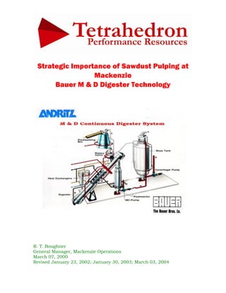
  • 2. Bauer M & D Digester Technology The Bauer M & D digester system was initially developed by Bauer Brothers Company in the late 1950s. Bauer’s Canadian headquarters was in Brantford, Ontario. The initial concept was developed by two of Bauer’s staff, H.S. Messing and C.L. Durkee, after whom the process is named. It is covered under Canadian patents 893,465 and 928,546 and is also patented in the United States, Austria, Finland, Brazil and a number of other countries. In a classic ongoing story of merger, acquisition and divestment, Bauer Brothers was acquired by Combustion Engineering in 1973. In 1989, Combustion Engineering was, in turn acquired by ASEA Brown Boveri. ABB then decided that the Sprout-Bauer division, a merger of Bauer Brothers and Sprout-Waldron put together by Combustion Engineering, did not fit their strategic vision; Sprout-Bauer was sold to Andritz in 1990. As of the late 1990s, the Andritz M & D digester was no longer the only one available since, due to patent expiry, Ahlstrom, was also offering the M & D. As of April 2000, however, Andritz is in the process of acquiring Ahlstrom. Strategic Importance of Sawdust Pulping As a strategic Pope & Talbot, Inc. corporate capability, we are now producing 108,000 ADt per year of short fibre pulp from sawdust. With no other significant consumer of sawdust within viable transportation distance, this 220,000 BDU per year of sawdust had been burned, with subsequent environmental impact, prior to the startup our sawdust pulping line late in 1996. Our sawdust consumption is supplied from the Mackenzie sawmills of Canfor Corporation 50%, Abitibi-Consolidated 10-15% with the remainder coming from Winton Global in Bear Lake 10-12% and Canfor in Chetwynd 20-25%. Our Andritz-Bauer M & D digester installation consumes the equivalent of what five beehive incinerators would earlier have incinerated in the region, and does so with no atmospheric discharge of particulate.
  • 3. Unloading, Storage and Reclaiming The short fibre handling and storage system is a series of conveyors, chutes, reclaims and auxiliary equipment that transports truck-delivered sawdust and shavings to the surge bin ahead of the M & D digester. The system starts at the Megatech drive-through truck dumper 20-1100 from which the fibre is dumped into a hopper. The dumper is an 85-foot tilt-table system designed for six truckloads per hour at a nominal 20 BDU/load. Four 4-stage hydraulic cylinders of 11 7/8”, 10 3/8”, 9 1/8” and 7 7/8” cylinder diameter and 40-ft extension raise the table to a 63-degree incline to permit the chips to dump by gravity into the receiving hopper. The hopper is 32 feet long and 22 feet wide at the top to receive the flow out of the trailer and converges to 34 feet long and 10 feet wide over the live bottom. It is 17 feet deep at the north end and 8 feet deep at the south end as the live bottom conveyor 20-1130 is inclined 150 upwards towards the discharge. The chain conveyor is 10 feet wide and 33 feet long and is hydraulically driven by a Hagglunds Marathon MB 400 hydraulic drive. The conveyor discharges onto the #1 unloading conveyor 20-1150. This #1 belt conveyor is a 40 foot long 48-inch belt conveyor that serves to lift the fibre stream 9 feet from the low elevation at the drop-off from the bin bottom and lifts it high enough to dump onto #2 unloading conveyor 20-1160. #2 is another 48-inch belt unit running perpendicular to the #1 with a 478-foot long run sufficient to lift the fibre stream 112 feet vertically from below ground to an elevation above the height of the storage piles. The transfer point between #2 unloading conveyor and #3 unloading conveyor is located in the transfer tower 80 feet above the ground at the elevation above the top of the three conical sawdust piles. The #3 unloading conveyor 20-1180 is a 54- inch belt that has an initial uphill run but essentially runs out 352 feet horizontally to the east, above the three piles. It has three adjustable plows with “elephant trunk” telescopic chutes to form the three conical short fibre piles which are centred 75 to 100 feet apart.
  • 4. Under the sawdust/shavings storage pile are two Andritz-Kone slewing screw reclaimers 17-1100 and 17-1110, each of which rotates 360° like the hands on a clock with a 41 foot working radius. The fibre stream from the reclaims is fed onto #1 infeed belt conveyor 17-1140, a 30-inch belt which runs 395 feet to the east with a 43 foot lift and, in turn, discharges under a self cleaning magnet onto the Acrowood 648 disk- type scalping screen 17-1150. With the big chunks removed, the fibre stream from the scalping screen discharges onto #2 infeed conveyor 17-1160 , a 48-inch belt which runs 588 feet to the southeast with a 127 foot lift and delivers into the top of the Kone surge bin. Due to the long run it has a counterweight-type tensioning device with a 20-25-ft drop at midlength.
  • 5. Sawdust Bin 31-1205 and Bin Discharger 31-1210 Sawdust from the 48-inch #2 infeed conveyor discharges at a transfer point that is 130 feet above the ground, into the top of the surge bin. The surge bin is 35 feet high and expands in diameter from 10.5 feet at the top to 13.5 feet at the bottom. The negative taper minimizes the risk of hang-ups. The bin nominal capacity of 90 cubic metres or 12 BDU provides 20-25 minutes retention time Attached to the bottom of the bin is the Andritz-Kone 4-armed HELP bin discharger with double-cylinder hydraulically drive: 31-1212 and 31-1213. This device scrapes back and forth across the bottom of the bin to ensure a constant positive delivery of sawdust to the metering screw conveyor. The action of the discharger, which sweeps the entire bottom surface of the bin, along with the shape of the bin itself, ensures a uniform plug flow. This minimizes channelling of sawdust down through the bin. The discharger loosens the compaction at the bottom level of the bin and permits the sawdust to drop by gravity into the metering screw. Digester Feed Metering Screw 31-1215 The Andritz-Kone metering screw is driven by a Hagglunds Viking UK44-03300 hydraulic drive and provides accurate metering of sawdust to the digester and an initial impregnation with weak black liquor injected through nozzles, into the sawdust. The metering screw is the device that determines the system production. The geometrically determined delivery rate is 3.9 cubic feet per revolution. Operating speed is about 30 RPM which delivers almost 120 ft3 per minute, a rate corresponding to 330 unbleached tonnes per day. Variations in screw pitch allow for the even draw down from the bin and ensure a full volume of this screw into the metering shroud. At the discharge of the metering shroud, the screw pitch is doubled to provide an even flow of raw material into the rotary valve. The original process design had allowed for presteaming provided in the metering screw by utilizing all of the vented steam from the rotary valve. Flash steam was to enter the dome of the metering screw, so that any sawdust carried over in the vent steam is returned to the digester infeed. This was never successful, however, probably
  • 6. due to the fluffy nature of our “sawdust”. Instead, weak black liquor dilution at 100- 150 usgpm is supplied to the top of the metering screw to improve feeding. The source of the black liquor is from the D-D washer filtrate tank. As the screw is filled in the metering shroud, the steam is forced through the bulkhead into a cavity above the screw. A differential pressure cell is mounted on the feed end of the metering screw to indicate the pressure in the metering screw. The presteamer is connected to the rotary valve through a downspout. The downspout is attached to the rotary valve so that the flow of raw material approaches the valve nozzle from the small diameter end of the valve. Inlet Rotary Valve 31-1225 Compared to the more-familiar Kamyr digester system, the rotary valve, in spite of the deceptively simple name, performs the roles of the low pressure feeder, steaming vessel, high pressure feeder and top separator. Accomplishing that is a precision machine that stands 60” high, outlet flange to inlet flange and weighs 8 tonnes. It has 17 ports, ranging in size from the 42” rotor insertion port to the two 1” white liquor injection ports. The unit is an Andritz-Bauer model 2000 H, driven by a Hagglunds Marathon MA 200 hydraulic drive and designed to transfer sawdust starting from atmospheric pressure and ending in the high pressure conditions of the main M & D digester vessel and to preheat the sawdust. The geometrically determined delivery rate is 6.7 cubic feet per revolution. The drive end cover plate is 48.75” diameter and the adjusting end cover plate is 39.0” diameter. The rotor tapers from 32” diameter at the back end to 41” diameter at the front end and measures 27”, along the length of the shaft. The 1:6 ratio of radius change per axial distance means a 6mm axial shift corresponds to a 1mm change in radius or 2mm change in diameter. The body is a rugged, thick wall steel casting to provide dimensional stability throughout the expected range of temperatures and pressures. The body is overlaid with hardened Inconel 625 steel and also has stellite on the rotor seat surfaces. This overlay is replaced each time the valve is overhauled annually.
  • 7. Viewed from the adjusting end, farthest from the stairwell, the valve rotates clockwise. Understanding the operation is helped by visualizing the ten pockets and corresponding ten pocket positions. Consider the orientation with the dividing vane vertical; positions 1-5 are on the descending side and positions 6-10 on the rising side. Sawdust from the metering screw drops through the 26” inlet port in positions #10 and #1, into the valve rotor which makes a half rotation and drops the sawdust out through the 28” outlet port at the #5 and #6 position, down into the main digester vessel. The rotor’s ten pockets successively fill and empty. Typical operating speed of the rotary valve is 65% of the metering screw speed so should be about 20 RPM which delivers about 135 ft3 per minute at a 330 tpd production rate. This corresponds to about 30 RPM on the metering screw and the rotary valve volumetric delivery rate is about 115% of that of the metering screw to provide a “take-away” factor to prevent “backup”. The steaming vessel function is performed through the injection of recycled steam and fresh virgin steam in sequence to elevate the pocket pressure from atmospheric to digester conditions and then back down again through the rotation. After being filled with sawdust in the #10 and #1 positions, the pocket moves to #2 position where end bell relief recycled steam enters through a 4” diameter connection to elevate the pressure to 20 psig. Next, in the #3 position, the primary exhaust steam from the high pressure side comes in through a 4" connection at lowest point of the pocket to further elevate pressure to 60 psig. Together, these recycled streams provide the first phase of preheating to digester conditions. The preheating is completed with three 190 psig steam connections by injection of 10,000-12,000 lb/hr of fresh steam. First, through the 2” FCV “A” which generally runs wide open, pre-purge steam comes into the #4 position from the header through two 1” nozzles that enter radially, one at each end of the pocket. These channel steam to the bottom of the pocket to aid in blowing the sticky wetted sawdust out of the pocket and finish elevating pocket pressure toward digester pressure. As the pocket reaches the discharge nozzle at the #5 position, the sawdust falls down into the digester inlet. Nozzle purge steam can be supplied through 4” FCV “C” through a 6” nozzle, pointing downwards below the #5 position, to keep the discharge passage down to the digester clear. Generally this is not run since it causes back pressure and restricts pocket emptying. In the #6 position, emptying is completed by pocket purge steam supplied through 6” FCV “B” through a 6” nozzle on rising side of
  • 8. the pocket directed by a turning plenum upward to scour the pocket clear of residual sawdust. This valve generally runs 45-50% open. As the pocket passes the #7 position, it is cleanly emptied but holding digester pressure which must be vented. There are two more nozzles, 2” in diameter, located on the 28” diameter bottom discharge nozzle of the rotary valve. These allow for the direct addition of a portion of the white liquor charge. The first phase of depressurization occurs in the #8 position where the primary exhaust port, a 4” nozzle drops the pressure to about 70 psig by allowing transfer, as noted above, around to the #3 pocket which operates at about 60 psig. As the pocket moves into the #9 position, the trailing vane is passing the 16” secondary exhaust port which allows depressurization to 3-5 psig by venting up the pipe to the sawdust bin for most effective re-use. The pocket then moves into the #10 position at the top where filling begins, to initiate a new cycle. With a 10-pocket rotor and the rotor at 15 RPM, there are 150 pocket-cycles per minute. The most apparent indicator of this frequency is the rapid chug-chug-chug pattern as the pockets pass the secondary exhaust port in the 8 o’clock position. During operation, small quantities of steam and sawdust blow through the operating clearance between the rotor and the valve body and on into the end bell cavities of the rotary valve. This material is exhausted from the end bells through the manifolds to the previously mentioned 16” diameter connection at the 2 o’clock position and back into the feed pockets. This relieving of the end bell pressure improves feeding efficiency and reduces loading on the thrust bearings packing. If the rotor is poorly seated, the clearance between the rotor and the housing is too great and sawdust build-up in the end bells further aggravates seating, resulting in excessive steam blowback up into the metering screw, ultimately stalling it out. Mackenzie’s species mix is the same blend that makes our MK – 90 chip pulp a global quality leader: 40% western white spruce, Picea glauca, 40% lodgepole pine, Pinus contorta and 20% alpine fir, Abies lasiocarpa. But the characteristics of our “sawdust” furnish are significantly different from typical sawdust. It is 20% green saw kerf and 20% green chip screens undersize fraction; this portion is typical. The other 60% is planer shavings; lumber is planed after the drying kilns, so this 60% is kiln dried. The overall feed stream has an average bulk density of 9.25 OD lb/ft3 or 150 kg/m3. The moisture content ranges 10-30%, very dry by conventional standards. The general arrangement elevation views of the principal sawdust pulping process equipment: sawdust bin, M & D digester, surge tube, blow tank, brown stock washer and auxiliaries are shown in the following views from the east looking west and from the south looking north.
  • 9.
  • 10. Bauer Digester Vessel 31-1230 Our M & D digester is a nominal 300 tonne per day unit, 90 feet long flange to flange, 100 inches diameter for a calculated volume of 5,175 ft3 and nominal working volume of 3,450 ft3, mounted at the M & D characteristic 450 angle. It was fabricated by Nooter Corporation in St. Louis, Missouri in 1996 and is rated for 200 psig and 400 0F. It is divided into upper and lower halves by the midfeather. The internal chain conveyor moves the fibre from the discharge of the rotary valve down the upper side of the midfeather to the bottom of the digester and back up the underside to the outlet to the surge tube at the top end. It is driven by a hagglunds Marathon MB 400 hydraulic drive on the head shaft. This 450 inclination gives the M & D digester its uniquely characteristic features of the vapour phase impregnation zone at the inlet as in the Kamyr and Impco designs along with the positive movement and guaranteed retention time associated with the Black Clawson Pandia digester. The decantation and vapour phase blow stream is unique to this design. The Digester operating pressure of 150 psig is maintained by the injection of 25,000- 35,000 lb/hr of 190 psig steam to the inlet rotary valve. As a pressure vessel, the digester is designed for a maximum pressure of 200 psig and a maximum temperature of 400 0F. Digester operating temperature is controlled by the combined effects of direct injection of 190 psig steam to the digester body and assisted by 8500- 10,000 lb/hr of 80 psig steam to the liquor heater which raise the liquor temperature to 300 0F. This digester design provides the potential for three distinct temperature zones: top, mid- and bottom although at Mackenzie we generally run at 350-3600F throughout. It is particularly critical to maintain a bottom temperature of 355-358 0F. The chain conveyor speed is adjusted according to production rate and head shaft rotational speed should be about 2.4% of the metering screw speed. So at a 300 tonne per day production rate at 28 RPM on the metering screw, the head shaft speed would be about 0.67 RPM. The running mechanism consists of two 11.625” diameter steel shafts: head shaft at the upper end and tail shaft at the lower end. The head shaft is driven by a Hagglunds Marathom MB 400 hydraulic motor; the tail shaft is an idler with tension adjustment capability. The upper shaft has a pair of 39” diameter 12-tooth sprockets mounted on the shaft, centred about 50 inches apart. The lower shaft is attached to a
  • 11. hemispherical inner head that forms a housing, similar in section to the lower head of the vessel. This hemispherical head and lower idler shaft are permitted to move in the inward direction along the digester axis. The degree of this movement is controlled by a shaft attached to the idler lower end and extending through the bottom head of the digester for connection to compression springs. The hemispherical inner head and lower idler shaft are limited in outward movement to indicate chain wear and keep spring force at design load. The chain assembly consists of two parallel strands of 20” links, one running on each pair of upper and lower sprockets. There is a conveying flight on every third link for a total of 36 flights. The size and shape can be described as a segment of a 100” diameter circle, cut by a chord 20” displaced from the diameter, therefore enclosed by 1330 of the circumference. That makes it approximately 90 inches wide along the chord and 30 inches maximum height, measured along the radius, chord to circumference. The flights are bent on a line, parallel to the base and 16” away from the base to provide a 1400 included angle, making a pocket effect. At a typical chain speed of 0.58 RPM on the head shaft, the chain will travel at 6 feet per minute, or 10 feet per sprocket revolution, and the180 foot running length of the chain will make a cycle in 30 minutes. The chain running length, inlet nozzle to outlet nozzle is 159 feet and with a normal liquor volume of about 85% of the total vessel volume, the liquor phase cooking time would be about 25 minutes. Once retention time is set, K-no control is achieved by adjusting the E.A.:wood ratio. The main cooking liquor addition is directly to the digester body and a smaller fraction to the rotary valve. White liquor at about 200 usgpm is diluted with about 25 usgpm of weak black liquor and the combined stream is heated from 145 0F to 280 0F in the liquor heater before being injected into the upper shell. Cooking is essentially at constant H-factor; temperature at 355-365 0F or 180-185 0C and retention time at 20-24 minutes remain constant over the normal range of production rates.
  • 12.
  • 13. Thermocompressor 72-4001 and Desuperheater System Operation Because of its need for steam of higher pressure and temperature than other mill applications, the M & D digester system includes a Schutte & Koerting model 426 venturi-type thermocompressor to provide 190 psig steam. The unit is 101 inches overall length and has a 4” inlet for 625 psig steam, 6” inlet for 165 psig steam and a 6” outlet for 190 psig steam. Physically, it is oriented horizontally and installed along the west side, nearly at the roof level of the Power Boiler, on the fourth floor level, adjacent to the power boiler drum and the two deaerator heads. The digester’s consumption rate of up to 35,000 lb/hr is produced by using 10,000 lb/hr of boiler header pressure steam at 625 psig to elevate the pressure of 25,000 lb/hr of 165 psig high pressure steam. Because of the proximity of supply of 625 psig steam, the thermocompressor is located in the Power & Recovery building although it is dedicated to the M & D digester. Outlet Surge Tube 31-1240 Cooked fibre discharges by gravity from the digester vessel into the surge tube. The surge tube is nominally 50 feet high and 90 inches in diameter, with a vertically mounted bottom agitator, 31-1255, providing five minutes retention time at typical conditions. The stock temperature is reduced from 350 0F at the top inlet to 280 0F at the bottom outlet by recirculation of about 200 usgpm of weak black liquor filtrate from the D-D washer first stage filtrate tank. The liquor for both surge tube dilution and subsequent further dilution in the blow tank is cooled from 185 0F to 125 0F by circulation through the filtrate cooler before return to the surge tube. The cooling water from the cooler is at 160 0F and goes to the hot water system. The stock is then directed to one of two blow lines to the blow tank. There is a sampling device off the surge tube for stock tests. Blow Tank 31-1260 The stock enters the flat bottom short fibre blow tank at approximately 5.5% consistency. The blow tank has an overall height of 70 feet and a nominal volume of 24,000 cubic feet or 180,000 usgal. The main storage section of the blow tank is 26’- 3” feet in diameter and 48 feet high for a nominal capacity of 100 ADt. The bottom of the blow tank is a 16’-6” foot diameter, 12 feet high dilution zone with side-mounted agitator, 31-1265. About 200 usgpm of primary dilution is added to the bottom zone of the tank itself and another 100 usgpm is added as secondary dilution to the pump suction. This dilution supply is also cooled in the filtrate cooler. The stock transfer pump, 31-1270
  • 14. delivers to the Ahlstrom D-D (drum displacer) but this next washing phase of the operation is beyond the scope of this section. Blow Heat Cyclone 31-1261 and Vent Condenser 31-1290 The blow tank is equipped with a vent system consisting of a blow heat cyclone and vent condenser. The cyclone underflow returns by gravity to the blow tank. This cyclone separates any entrained stock from the gas stream. The “cleaned” vapour stream then and passes on to the vent condenser which condenses any condensable gases with the resulting foul condensate pumped to the evaporator seal tank. The remaining stream of noncondensibles, (NGGs) goes on to the Kamyr relief condenser. Stock spills in the digester area are collected in the spill recovery sump. They are then pumped to the clean fibre salvage or to general sewer. Short Fibre Brown Stock Washing The heart of the Andritz-Ahlstrom 4040 drum displacer washer 34-1100 is a rotating drum, 4.00 meters in diameter and 4.00 meters wide. The drum is driven by two Hagglunds Marathon MB 800 hydraulic drives, one on each end of the trunnion. The cylindrical surface has 40 axial compartments, each 4 metres long across the drum width and about 30 cm wide in the circumferential direction. Perforated screen plate material forms the bottom of the compartments. There is no traditional face wire or fabric required on the drum. Under the perforated plates are the filtrate compartments which are connected to the collection chambers at the end of the drum. The pulp at 3-9 psig enters the inlet box for
  • 15. even distribution into the pulp compartments on the drum face. It is then thickened into a uniform cake that fills each compartment in turn. Sealing bars separate the feed box from the washing zone and the outlet box. The sealing bar of the wash zone serves the second function of wiping off the pulp cake so the compartments are uniformly filled as they enter the wash zone. The closed pressurized feed box, stable control of feed pressure and precise thickness of the cake to be washed all combine to achieve very efficient washing. The discharge sheet consistency ranges from 9-13%. Our D-D washer is a 3-stage unit. The wash liquor is distributed evenly from the washer casing at 7-15 psig over each wash zone. During washing, the pulp and filtrate compartments are hydraulically flooded to ensure air-free sheet formation and constant speed of displacement of the wash liquor through the sheet. The surface of the rotating drum has been divided into pockets by ribs surrounding the drum is a casing to which sealing elements are attached. Sealing elements separate different washing zones and are connected to the ribs. The feed zone extends from the 6:30 o’clock position to the 8:00 o’clock position; the first washing stage from 8:00 o’clock to 10:30; the second washing stage from 10:30 to 1:00 o’clock; the third washing stage from 1:00 to 4:00 o’clock; the thickening zone from 4:00 to 6:00 o’clock and the pulp outlet at the 6:30 position. The distribution valve connects the drum channels and filtrate circulation pipes for filtrate removal and counter-current washing. The distribution valve, located at one end of the drum, has been divided into sectors corresponding to the washing stages so the filtrates are not mixed. Filtrate from the thickening zone and from the first washing stage zone are discharged through two separate droplegs into the D-D washer filtrate tank 34-1150. It is 18’-0” in diameter and 21’-6” high, a nominal 32,000 usg tank with an internal seal well to submerge the discharge from each downleg. Weak black liquor from this tank is pumped to the main storage tanks, 60-1001 and 60-1002. The D-D washer can have 1 to 4 washing zones, depending on the application. Our washer has 3 washing zones. In addition, the washer has a feed zone and a discharge zone. Pulp is removed below the discharge zone by a discharge screw. The pulp is pumped to the feed zone at a pressure of 1.5 - 7.0 psig and at a consistency of 4.0 - 4.5 %. The pressurized pulp is thickened on the surface of the perforated plate of the drum and fills the pockets separated by the ribs. Concurrently the filtrate passes the perforated plate. When the pocket filled with pulp passes the first sealing element, excess pulp is wiped off keeping the thickness of the pulp cake constant. The feed pressure is controlled along with the feed consistency. This results in the porosity of the
  • 16. pulp cake being uniform. This gives the optimum washing result at each operating rate. The pulp cake entering the first washing zone is of uniform thickness and porosity and at 10 - 12 % consistency. As the drum rotates, 3 displacement washings are carried out using the counter-current washing principle. The dirtier liquor present in the pulp cake in the previous stage is displaced by the filtrate of the cleaner stage. Then the filtrate is fed to the previous dirtier stage as washing liquid. Filtrate from the decker filtrate tank is used as washing liquid in the third washing stage. The maximum pressure of the wash water is 14.5 psig. The pressure of the wash filtrate is increased somewhat by circulating filtrate pumps located between the washing stages. The complete washing and filtrate circulation is pressurized by the wash water pressure and intermediate filtrate pumps. This prevents the air from mixing with the pulp. From the last washing stage the pulp enters the discharge stage. When the cake is by the last sealing element, a connection opens from the filtrate channel to the vacuum pump which increases cake consistency by drawing the filtrate from below the perforated plate. After the cake has passed the suction point, a short pressurized air impulse is introduced below the perforated plate. This air impulse loosens the cake so the pulp falls onto the discharge screw. After the pulp has been discharged, the perforated plate of the drum is washed by the wash water showers. The perforated plate shower pump increases the shower water pressure to 116-145 psig. Washing of the perforated plate can occasionally be made more effective by the supplying the showers through the high-pressure wash pipe, e.g. with wash intervals of 5 min. The maximum allowable wash water pressure in the pipe is 1450 psig.
  • 17. Conclusion Our M & D digester based sawdust pulping system has been an extremely successful addition to the Mackenzie facility. Higher temperature-pressure and higher alkali:wood charge makes the M & D digester a high-intensity cooking machine! An M & D digester doesn’t have to “look big” to “produce big”. Volumetric productivity is 4-5 times that of a Kamyr or batch system…~60 tpd per 1,000 ft3 compared to ~15 tpd per 1,000 ft3. Tom Boughner Mill Manager, Pulp Operations Norske Skog Mackenzie September 20, 2000