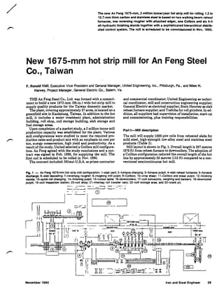
The document summarizes a new hot strip mill being commissioned in November 1990 for An Feng Steel Co. in Taiwan. The key details are:
1) The mill has a production capacity of 2 million tonnes per year and can roll strips from 1.2-12.7mm thick in carbon and stainless steel.
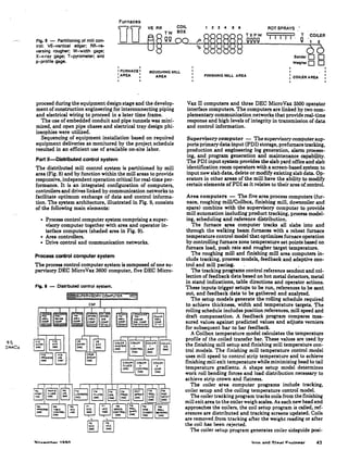
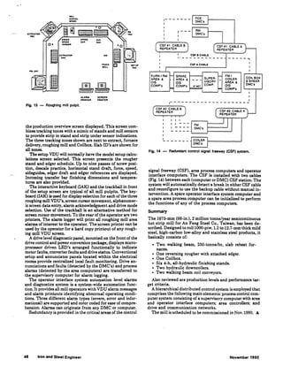
2) It features two walking beam reheat furnaces, one reversing rougher, a coilbox, six finishing stands, and two downcoilers.
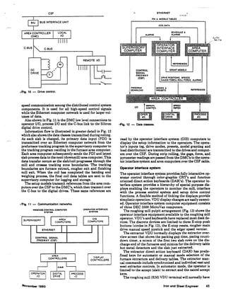
3) The distributed control system partitions control by mill area and function to provide responsive independent operation for real-time performance.