Downloaded 103 times


![Ways of Inducing an emf
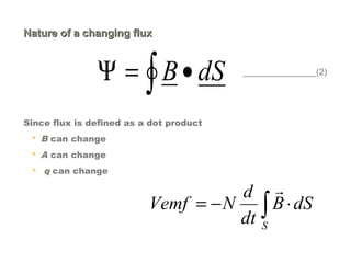
1. A stationary loop in a time varying magnetic field B [TRANSFORMER EMF]
i.e. The magnitude of the magnetic field can change with time.
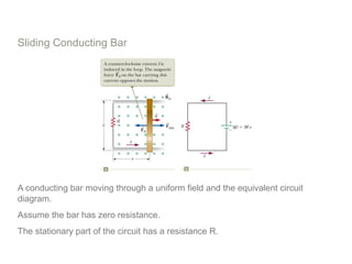
2. A time varying loop area in a static field B [ MOTIONAL EMF]
i.e., The area enclosed by the loop can change with time.
3. Time varying loop area in a time varying magnetic field
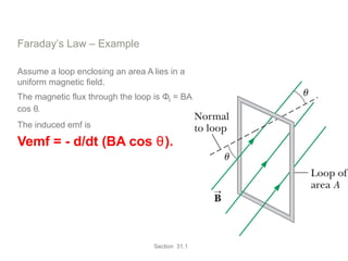
i.e., The angle between the magnetic field and the normal to the loop can change
with time.
Any combination of the above can occur.](https://image.slidesharecdn.com/maxwellequation-130416114309-phpapp02/85/Maxwell-equation-23-320.jpg)
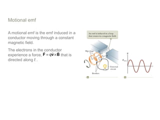

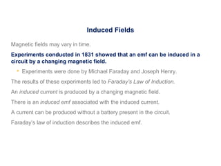
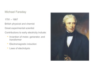
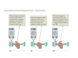
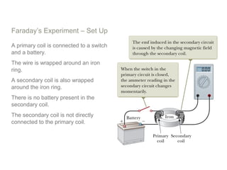
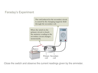
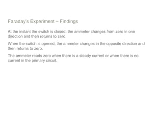
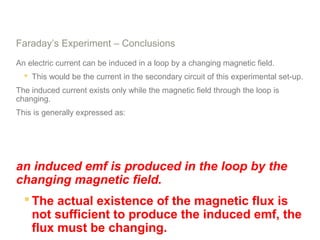
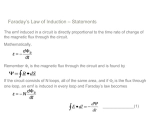
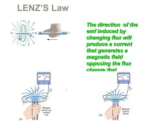
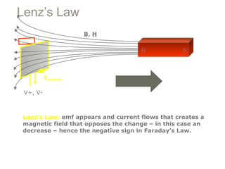
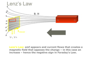
Experiments in 1831 by Faraday and Henry showed that an emf can be induced in a circuit by a changing magnetic field. This led to the discovery of electromagnetic induction and Faraday's Law of Induction. According to Faraday's law, an induced emf is produced by the time rate of change of the magnetic flux through a circuit. Lenz's law describes how the direction of the induced current will be such that it creates an opposing magnetic field to the change that created it.