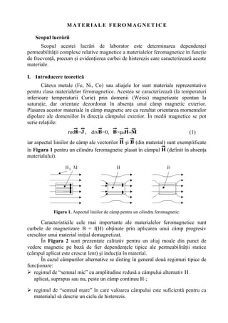
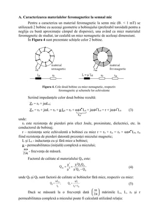
Chapter3 introduction to the quantum theory of solidsK. M.
The document provides an introduction to the quantum theory of solids, including:
1. How allowed and forbidden energy bands form in solids due to the interaction of atomic electron wave functions when atoms are brought close together in a crystal lattice.
2. Electrical conduction in solids is explained using the concept of electron effective mass and holes, within the framework of the energy band model.
3. The Kronig-Penney model is used to quantitatively relate the energy, wave number, and periodic potential within a solid, resulting in allowed and forbidden energy bands.
Basic of semiconductors and optical propertiesKamran Ansari
This presentation explains the band structure, intrinsic semiconductor, extrinsic semiconductor, electrical conductivity, mobility, hall effect, p-n junction diode, tunnel diode and optical properties of the semiconductor.
This document discusses semiconductor physics concepts including:
1. Semiconductors have long-range symmetry of atomic arrangement and are mostly crystalline materials. They have a moderate bandgap (1-2 eV) compared to insulators (6 eV).
2. Semiconductors have a valence band and conduction band separated by an energy gap. At higher temperatures, electrons can gain enough energy to cross this gap and contribute to conductivity.
3. Semiconductors are classified as intrinsic or extrinsic. Extrinsic semiconductors have impurities added which create majority carriers, making them either n-type or p-type.
4. The position of the Fermi energy level depends on whether
Electric cells convert chemical energy into electrical energy to produce electricity. Multiple cells connected together form a battery. Batteries produce a potential difference across their terminals through chemical reactions, providing energy to move electrons through an external circuit. The electromotive force (emf) of a battery is the voltage when no current flows, while internal resistance causes voltage to drop under load. Batteries can be connected in series, where the total emf is the sum of individual cells and current is the same through each, or in parallel, where the total current is the sum of individual cells and voltage is the same across each.
1) The document discusses various concepts related to electrostatics including capacitance, capacitors, and dielectrics. It defines capacitance as the ability of a conductor to store charge and explains the factors that affect capacitance such as area and distance of separation for a parallel plate capacitor.
2) Energy storage in capacitors is also covered, explaining that work must be done to charge a capacitor and this work is stored as electrostatic potential energy. Expressions are given for calculating energy stored in series and parallel combinations of capacitors.
3) The document introduces the concept of dielectrics, noting that polar molecules can have their dipole moments aligned by an electric field to induce polarization while non-polar
This document discusses MOS field-effect transistors (MOSFETs) and includes the following topics:
1. It outlines the structure and operation of MOSFET devices, including creating a channel for current flow and deriving the iD-vDS relationship.
2. It covers current-voltage characteristics of MOSFETs such as the iD-vDS, iD-vGS curves and their different operating regions.
3. It provides examples of solving for unknown variables in MOSFET circuits operating in different regions, such as the triode and saturation regions.
Molecular orbital theory describes how atomic orbitals combine to form molecular orbitals in molecules. When atoms bond, their atomic orbitals overlap and interact to form new molecular orbitals that are shared between the bonded atoms. Electrons occupy these molecular orbitals rather than the individual atomic orbitals. Molecular orbital diagrams illustrate the relative energies of the molecular orbitals and how electrons fill them according to certain rules. Molecular orbital theory can be used to explain bonding properties in diatomic and more complex polyatomic molecules.
This document discusses solids and semiconductor devices. It begins by explaining the electrical conductivity of different materials like conductors, semiconductors, and insulators. It then describes the energy band structure of solids, noting that semiconductors have a small band gap between the valence and conduction bands. The document discusses intrinsic and doped semiconductors, including n-type and p-type materials. It also covers diodes, p-n junctions, and how they function when forward and reverse biased. Key concepts covered include band theory, hole-electron pairs, and improving conductivity through doping.
A current transformer (CT) is used to measure large currents and reduces the measured current proportionally based on its turns ratio. It works by using the secondary side of a voltage transformer model as the current sensor, which transforms the current by the inverse of the turns ratio from one side to the other. Additional parameters like the equivalent magnetizing inductance, resistance, and capacitance can be added to the model to improve accuracy and limit its frequency range.
Magnetism and electromagnetism are reviewed. Magnets have north and south poles that attract or repel. A magnetic field is created around magnets and currents. The motor effect occurs when a current-carrying conductor experiences a force in a magnetic field. Applications include electric motors and loudspeakers. Electromagnetic induction generates a voltage in a conductor moving in a magnetic field or vice versa. Alternating current generators use this principle with a coil rotating in a magnetic field.
This document provides an introductory lecture on electrostatic lenses. It begins with an overview of the goals and objectives, which are to provide knowledge of the analogies between charged particle and light optics, and the ability to calculate the focal and aberration properties of lenses and design beam transport systems. It then discusses what electrostatic lenses are, how they work similarly to optical lenses but with some key differences due to properties of charged particles. The document covers lens parameters like focal length and planes, and how lenses can focus or diverge beams. It also discusses simulation tools and recommended reading on this topic.
This document discusses electromagnetic induction and Faraday's law. It explains that magnetic fields have flux lines that run from the North to South pole of a magnet. The flux Φ is calculated as BA sinθ and represents the strength of the magnetic field times the area it passes through. Faraday's law states that an electromotive force (EMF) is induced in a conductor when it passes through a changing magnetic flux. The EMF is directly proportional to the rate of change of flux linkage over time. For a coil of N turns, the EMF induced is equal to -N * (change in flux linkage over time).
This document provides information on band theory and semiconductor physics. It discusses how energy bands are formed in solids due to the interaction of atoms. Energy bands split into discrete energy levels for insulators and partially overlapping bands for conductors and semiconductors. Semiconductors have a small band gap that can be modified by doping to create n-type or p-type materials. A p-n junction forms the basic structure of a diode and transistor. The document explains concepts such as Fermi levels, carrier transport, and device characteristics like the I-V curve and modes of transistor operation. Applications of semiconductors include rectifiers and basic logic functions.
1) The document provides an overview of elementary quantum physics concepts including the photoelectric effect, blackbody radiation, quantum tunneling, the hydrogen atom model, electron spin, and selection rules for photon emission and absorption.
2) Key topics covered include Planck's quantization of energy, De Broglie's matter waves, Heisenberg's uncertainty principle, Schrodinger's equation, and the quantization of angular momentum.
3) Experiments are described that provided evidence for the quantum nature of light and matter, including the photoelectric effect, Compton scattering, electron diffraction, and scanning tunneling microscopy.
The present article gives the fundamental properties magnetism, different materials, properties of different magnetic materials like, dia,para and ferro magnetic materials. The notes also explain how magnetism appear in materials, type of magnets and brief applications of magnetic materials. The materials is best for undergraduate science and engineering students and any other people of interest in magnetism
Dielectric and Magnetic Properties of materials,Polarizability,Dielectic loss...A K Mishra
In this PPT contains ,Dia,Para,Ferromagnetism,Clausius-Mossoti equation,Dielectric Loss ,Hysteresis,Hysteresis loss and its Applications,Determination of susceptibility,types of polarisation in mateials,relative permability
This document summarizes key topics related to electronics devices and circuits, including:
1) The operation and characteristics of unbiased, forward biased, and reverse biased diodes. Forward biasing reduces the depletion region and allows current to flow, while reverse biasing increases the depletion region and prevents current.
2) Breakdown mechanisms including avalanche and Zener effects which allow current to flow under high reverse voltages.
3) Energy bands and levels that describe the quantum mechanical states of electrons in materials, and how semiconductor materials have a forbidden gap between valence and conduction bands.
4) How the barrier potential of a p-n junction decreases with increasing temperature, allowing more current to flow.
1. Inside metals, electrons are weakly bound to atoms and move freely through the metal.
2. These free electrons move through a periodic potential created by the positive ions and other electrons.
3. The potential energy of the electrons is periodic inside the metal but rises suddenly at the boundaries, as shown in the figures. Electrons with energy below a binding energy Eb are tightly bound to atoms, while higher energy electrons between Eb and the Fermi energy Ef can move through the metal.
1) Electromagnetic induction occurs when the magnetic flux through a circuit changes, inducing an emf and current based on Faraday's laws.
2) Lenz's law states that the direction of induced current will oppose the change producing it, in accordance with the law of conservation of energy.
3) The magnitude of induced emf is proportional to the rate of change of magnetic flux through the circuit according to Faraday's second law. Induced emf can be produced by changing the magnetic field strength, area of the coil, or relative orientation between the coil and magnetic field.
This document discusses the Drude model for explaining the optical and electric properties of metals using a free electron gas model. It describes how the Drude model relates the dielectric constant of metals to oscillations of free electrons in response to an applied electromagnetic field. It defines key terms like plasma frequency, damping frequency, and presents equations for the real and imaginary components of the dielectric function and how they describe polarization and energy dissipation in metals. Graphs are shown depicting how the real part of permittivity is negative at lower frequencies but becomes zero near the plasma frequency.
This document classifies and defines different types of magnetic materials:
- Ferromagnetic materials can form permanent magnets and are strongly attracted to magnetic fields. Ferrimagnetic materials also have populations of atoms with opposing but unequal magnetic moments.
- Paramagnetic materials are only attracted to external magnetic fields and have relative permeability greater than 1.
- Diamagnetic materials are repelled by external magnetic fields and have relative permeability less than 1. Diamagnetism is a weak quantum effect in all materials.
This document discusses applications of superconductors. It begins with a brief history of superconductivity and summarizes some key theories like London theory, Ginzburg-Landau theory, and BCS theory. It then discusses properties of superconductors like zero electrical resistance, perfect diamagnetism, and critical magnetic field. Finally, it describes potential applications of superconductors such as superconducting generators that could improve efficiency, superconducting magnetic energy storage systems, and superconducting cables.
The document discusses the aim and procedure of an experiment to investigate the relationship between the input and output voltage and number of turns in the primary and secondary coils of a self-made transformer. The experiment involves creating step-up and step-down transformers using an iron core wrapped with copper wire coils and measuring the voltage and current in the primary and secondary coils. Key findings are that output voltage is directly proportional to the ratio of turns in the secondary coil to the primary coil, and that transformers can increase or decrease voltage while decreasing or increasing current by the same ratio.
The document discusses the development of quantum electrodynamics (QED) from its origins in Dirac's 1927 paper on the quantum theory of radiation. It provides an overview of the key topics covered in the subsequent chapters, including particles and fields, quantization of the electromagnetic field, Feynman diagrams, and renormalization in QED. The goal is to show how electrons and photons interact using quantum field theory by representing particles as excitations of underlying fields and developing perturbative techniques to calculate processes like scattering and radiation.
This document discusses logical gates and their truth tables. It defines the NOT, AND, OR, NAND, NOR, XOR, and NXOR logical gates and provides their truth tables showing the output for all combinations of 0 and 1 inputs. The truth tables define the output of each logical gate based on the inputs.
1. MATERIALE FEROMAGNETICE
Scopul lucrării
Scopul acestei lucrări de laborator este determinarea dependenţei
permeabilităţii complexe relative magnetice a materialelor feromagnetice in funcţie
de frecvenţă, precum şi evidenţierea curbei de histerezis care caracterizează aceste
materiale.
I. Introducere teoretică
Câteva metale (Fe, Ni, Co) sau aliajele lor sunt materiale reprezentative
pentru clasa materialelor feromagnetice. Acestea se caracterizează (la temperaturi
inferioare temperaturii Curie) prin domenii (Weiss) magnetizate spontan la
saturaţie, dar orientate dezordonat în absenţa unui câmp magnetic exterior.
Plasarea acestor materiale în câmp magnetic are ca rezultat orientarea momentelor
dipolare ale domeniilor în direcţia câmpului exterior. În medii magnetice se pot
scrie relaţiile:
rot = , div =0, =µ0 + (1)
iar aspectul liniilor de câmp ale vectorilor şi (din material) sunt exemplificate
în Figura 1 pentru un cilindru feromagnetic plasat în câmpul (definit în absenţa
materialului).
Figura 1. Aspectul liniilor de câmp pentru un cilindru feromagnetic.
Caracteristicile cele mai importante ale materialelor feromagnetice sunt
curbele de magnetizare B = f(H) obţinute prin aplicarea unui câmp progresiv
crescător unui material iniţial demagnetizat.
În Figura 2 sunt prezentate calitativ pentru un aliaj moale din punct de
vedere magnetic pe bază de fier dependenţele tipice ale permeabilităţii statice
(câmpul aplicat este crescut lent) şi inducţia în material.
În cazul câmpurilor alternative se disting în general două regimuri tipice de
funcţionare:
regimul de “semnal mic” cu amplitudine redusă a câmpului alternativ H~
aplicat, suprapus sau nu, peste un câmp continuu H=;
regimul de “semnal mare” în care valoarea câmpului este suficientă pentru ca
materialul să descrie un ciclu de histerezis.
2. Figura 2. Dependenţele µ(H) şi B(H) pentru un aliaj moale
din punct de vedere magnetic
În Figura 3 sunt prezentate aceste regimuri posibile, definindu-se
permeabilităţile uzuale: iniţială (I), reversibilă (II) şi de amplitudine (III).
Figura 3. Permeabilităţile uzuale pentru materialele feromagnetice
Datorită pierderilor de energie prin curenţi induşi (Foucault), histerezis,
magnetizare, permeabilitatea magnetică a materialului se defineşte (în complex
simplificat) ca fiind:
mj
00
e
H
B
H
B
j δ−
µ
=
µ
=µ′′−µ′=µ (2)
unde B şi H sunt fazorii inducţiei şi câmpului alternativ aplicat, iar δm este unghiul
de pierderi.
Din relaţia (2) rezultă că µ′ are în general semnificaţia definită în Figura 3,
iar
m
m
Q
1
tg =
µ ′′
µ′
=δ defineşte factorul de calitate Qm al materialului.
3. A. Caracterizarea materialelor feromagnetice la semnal mic
Pentru a caracteriza un material feromagnetic la semn mic (B~ < 1 mT) se
utilizează 2 bobine cu aceeaşi geometrie a bobinajului (preferabil toroidală pentru a
neglija cu bună aproximaţie câmpul de dispersie), una având ca miez materialul
feromagnetic de studiat, iar cealaltă un miez nemagnetic de aceleaşi dimensiuni.
În Figura 4 sunt prezentate schiţele celor 2 bobine.
Figura 4. Cele două bobine cu miez nemagnetic, respectiv
feromagnetic şi schemele lor echivalente
Scriind impedanţele celor două bobine rezultă:
Z0 = r0 + jωL0;
Zm = r0 + jωL = r0 + µL0 = r0 + ωµ′′ L0 + jωµ′L0 = r + jωµ′L0 (3)
unde:
r0 este rezistenţa de pierderi prin efect Joule, proximitate, dielectrici, etc. în
conductorul de bobinaj;
r – rezistenţa serie echivalentă a bobinei cu miez r = r0 + rm = r0 + ωµ′′ L0, rm
fiind rezistenţa de pierderi datorată prezenţei miezului magnetic;
L şi L0 - inductanţa cu şi fără miez a bobinei;
µ - permeabilitatea (iniţială) complexă a miezului;
π
ω
2
- frecvenţa de măsură.
Factorul de calitate al materialului Qm este:
b0
b0
m
QQ
QQ
Q
−µ′
µ′
=
µ ′′
µ′
= (4)
unde Q0 şi Qb sunt factorii de calitate ai bobinelor fără miez, respectiv cu miez:
m0
b
0
0
0
rr
L
Q;
r
L
Q
+
ω
=
ω
= (5)
Dacă se măsoară la o frecvenţă dată
π
ω
2
mărimile Lo, L, r0 şi r
permeabilitatea complexă a miezului poate fi calculată utilizând relaţia:
rm
4. 0
0
0 L
rr
j
L
L
j
ω
−
−=µ′′−µ′=µ (6)
Pentru caracterizarea miezurilor având geometrii diverse se utilizează “torul
de substituţie” (imaginar) care este “confecţionat” dintr-un material cu
permeabilitatea efectivă µe, având lungimea le şi aria Ae. Din condiţia ca torul de
substituţie, cu acelaşi număr de spire ca şi înfăşurarea pe miezul considerat, să
conducă la aceiaşi parametri magnetici rezultă dimensiunile şi permeabilitatea
efectivă, astfel:
;
C
C
l
2
2
1
e = ;
C
C
A
2
1
e =
;
A
l
C
i ii
i
1
e
∑ µ′
=µ′
(7)
∑==
i i
i
e
e
1
A
l
A
l
C ∑==
i
2
i
i
2
e
e
2
A
l
A
l
C
unde iµ′ , li şi Ai sunt parametrii permeabilitate magnetică, lungime şi arie
transversală a porţiunii omogene “i” a miezului considerat.
Inductanţa înfăşurării cu N spire pe miezul dat se poate estima pe baza
parametrilor torului de substituţie:
[ ] [ ]
[ ]mml
10mmAN104
HL
e
32
e
2
e
7 −−
⋅⋅⋅µ′⋅⋅π
= (8)
B. Caracterizarea materialelor feromagnetice la semnal mare
Pentru a caracteriza regimul de “semnal mare” se va vizualiza pe ecranul
osciloscopului ciclul dinamic de histerezis pentru un miez utilizând tehnica
figurilor Lissajous.
Principial, se va utiliza schema din Figura 5.
Figura 5. Schema principială pentru vizualizarea ciclului de histerezis.
Pentru deflexia pe orizontală (intrarea X):
( );tiRu 11x = ( )
( )
;
l
tiN
tH
e
11
= ( )tH
N
l
Ru
1
e
1x = (9)
de unde:
( ) ( ) ( )tH
k
1
tH
N
l
R
A
1
tx
x1
e
1
x
== (10)
5. unde Ax
div
V
este amplificarea pe canalul X al osciloscopului, iar kx este factorul
de scală corespunzător aceluiaşi canal.
Pentru deflexia verticală:
dt
dB
AN
dt
d
Nu e22y =
Φ
=′ (11)
( ) ( )∫∫ =
′
≈=
t
0
e2
y
t
0
2y tBAN
RC
1
dt
R
u
C
1
dtti
C
1
u (12)
deoarece:
)R
C
1
(uu yy <<
ω
>>′ (13)
Atunci:
( ) ( ) ( )tB
k
1
tBAN
RC
1
A
1
ty
y
e2
y
== (14)
unde Ay
div
V
este amplificarea pe canalul Y, iar ky este factorul de scală
corespunzător aceluiaşi canal.
Parametrii de scală pot fi calculaţi din (10) şi (14):
=
div
mA
lR
NA
k
e1
1x
x
=
div
T
AN
RCA
k
e2
y
y (15)
II. Desfăşurarea lucrării
1. Dependenţa de frecvenţă a permeabilităţii magnetice relative complexe.
Principiul de măsurare a fost prezentat în secţiunea I.A. Se va realiza
montajul din Figura 6 în care:
- B este bobina (cu sau fără miez) a cărei inductanţă L şi rezistenţă de pierderi de
tip serie r trebuie măsurate;
- G - generator sinusoidal (amplitudinea acestuia se fixează la U = 3 V);
- VE - voltmetru electronic (instrument de nul);
- R2 şi C2 sunt o rezistenţă şi un condensator reglabile (cutii decadice de
rezistoare, respectiv de condensatoare);
- R1 = R3 = 1 KΩ sunt rezistenţe fixe;
- Tr1:1 este un transformator de separare galvanică între masa generatorului G şi
a voltmetrului electronic VE.
6. Figura 6. Puntea Maxwell-Wien pentru determinarea
dependenţei de frecvenţă a permeabilităţii
magnetice relative complexe.
Principiul de determinare a inductanţei L şi rezistenţei de pierderi r ale bobinei
B folosind schema din Figura 6 (punte Maxwell-Wien) se bazează pe
particularităţile acestei punţi. Se observă în Figura 6 că puntea Maxwell-Wien se
alimentează pe o diagonală cu un semnal sinusoidal de frecvenţă reglabilă, iar pe
cealaltă diagonală se măsoară diferenţa de tensiune. Dacă este îndeplinită condiţia
de acord a punţii:
Z1·Z3 = Z2·Z4 (16)
unde Z1 şi Z3, respectiv Z2 şi Z4 sunt impedanţele de pe laturile opuse ale punţii,
atunci tensiunea măsurată de voltmetrul electronic VE este nulă, indiferent de
valoarea amplitudinii semnalului sinusoidal al generatorului G. Ţinând cont de
acestea măsurătorile se vor efectua în felul următor:
- se acordează puntea prin modificarea valorilor rezistenţei R2 şi a capacităţii C2
(cutii decadice);
Observaţie: Reglajul celor două cutii decadice se face alternativ, pornind de la
cifra cea mai semnificativă spre cea mai nesemnificativă, căutând ca indicaţia
voltmetrului electronic VE să devină minimă, acesta fiind pe scara cea mai
sensibilă!
- în momentul când acordul a fost realizat, valorile L şi r pot fi calculate din
condiţia de acord a punţii Maxwell-Wien, rezultând:
231 CRRL =
2
31
R
RR
r = (17)
Se dispune de 3 înfăşurări : bobina fără miez L0 (N=300 spire) şi bobinele L1
şi L2, identice din punct de vedere geometric şi având acelaşi număr de spire ca şi
L0, realizate pe miezuri din tole E+I din tablă de siliciu. Diferenţa între L1 şi L2
rezidă în modul de asamblare a miezului: pentru bobina L1 miezul este realizat din
tole întreţesute (fără întrefier), iar pentru bobina L2 din tole asamblate neîntreţesut,
cu întrefier.
7. Se conectează, pe rând, bobina L1, respectiv L2 în locul bobinei B din
Figura 6. Se fixează frecvenţa la valorile specificate în Tabelul 1 şi se face
acordul punţii pentru ca indicaţia voltmetrului electronic VE să fie minimă. Datele
obţinute se trec în Tabelul 1.
Tabelul 1
f [KHz] 0,5 0,8 1 2 5 8 10 12 15 18
Măsurători
Bobina fără
întrefier L1
C21 [µF]
R21 [Ω]
Bobina cu
întrefier L2
C21 [µF]
R21 [Ω]
Calcule
Bobina fără
întrefier L1
L1 [mH]
r1 [Ω]
µ′
µ′′
Bobina cu
întrefier L2
L2 [mH]
r2 [Ω]
efµ′
efµ′′
Se calculează L1, r1, L2 şi r2 din condiţiile de acord ale punţii Maxwell-Wien,
trecându-se datele în secţiunea a doua din Tabelul 1.
Se măsoară L0 şi r0 cu puntea BM 504 la f = 32 Hz şi f = 800 Hz. Se
completează Tabelul 2. Media acestor valori (vezi Tabelul 2) se va folosi pentru
calculul permeabilităţii relative complexe după cum se va arăta.
Tabelul 2
Bobina fără
miez L0
f [Hz] 32 800 Valorile medii
L0 [mH]
r0 [Ω]
Se va observa slaba dependenţă a valorilor L0 şi ro de frecvenţa de măsură în
domeniul frecvenţelor joase.
Se vor calcula cu ajutorul relaţiei (6) partea reală µ' şi cea imaginară µ''
pentru bobina fără întrefier L1, respectiv µ'ef şi µ''ef pentru bobina cu întrefier L2,
pentru cele 10 frecvenţe din Tabelul 1, completându-se secţiunea de calcule a
acestuia.
Pe baza Tabelului 1 se vor reprezenta grafic dependenţele µ'(f), µ''(f) şi
Qm(f), respectiv µ'ef(f), µ''ef(f) şi Qmef(f), unde Qm = µ' / µ'' şi Qmef(f) = µ'ef / µ''ef
sunt, respectiv, factorul de calitate al miezului magnetic pentru bobina fără
întrefier şi factorul de calitate echivalent pentru bobina cu întrefier. Cele 6 grafice
8. se vor realiza pe 3 diagrame diferite sau pe aceeaşi diagramă, însă cu scale diferite
pentru cele 3 mărimi. Explicaţia este următoarea: cele 3 mărimi studiate au game
de valori care diferă cu câteva ordine de mărime, astfel că reprezentarea lor pe o
diagramă cu o singură etalonare pe axa ordonatelor este practic imposibilă!
2. Caracterizarea materialelor feromagnetice în regim de semnal mare.
Principiul de măsură a fost prezentat în secţiunea I.B. Cu ajutorul schemei
din Figura 7 se vor vizualiza pe osciloscop curbele de histerezis dinamic pentru un
material feromagnetic (circuit magnetic închis) Tr1 şi pentru un material
ferimagnetic în două variante: Tr2 ( circuit magnetic închis) şi Tr3 (circuit magnetic
cu întrefier). Înfăşurările celor 3 transformatoare sunt identice ca geometrie şi
număr de spire (N = 1000 spire).
Figura 7. Montaj pentru vizualizarea caracteristicii de histerezis pentru diferite
miezuri magnetice şi pentru determinarea dependenţei µ = f(H).
Din relaţiile (10) şi (14) rezultă că tensiunile în punctele de măsură 1, 2 şi 3
sunt proporţionale cu inductia câmpului magnetic în miez B, iar căderea de
tensiune pe rezistenţa R1 este proporţională cu intensitatea câmpului magnetic H.
Se calculează constantele de scară kx şi ky folosind relaţiile (15) şi următorii
parametri ai torului de substituţie pentru miezurile considerate:
le = 190 mm Ae= 190 mm2
(18)
Se calibrează osciloscopul cu ajutorul generatorului intern de semnal
dreptunghiular, astfel încât amplificarea pe canalele X, respectiv Y să fie
Ax = 1V/div şi Ay = 0,1 V/div.
9. Se execută montajul din Figura 7 utilizând ambele canale Y(1,2) ale
osciloscopului pentru a vizualiza simultan ciclurile de histerezis ale miezurilor de
fier-siliciu Tr1 (tablă de siliciu 4%) şi ferită (fără întrefier) Tr2 pentru a compara
materialele. De asemenea, se vor vizualiza simultan ciclurile corespunzătoare
miezului de ferită Tr2 (circuit magnetic închis, fără întrefier) şi miezului de ferită cu
întrefier Tr3 pentru a pune în evidenţă influenţa întrefierului asupra proprietăţilor
magnetice de material.
Observaţie: Înainte ca generatorul să fie cuplat la reţea nivelul acestuia va fi redus
la minim pentru ca apoi să fie crescut progresiv.
Se va lucra la frecvenţele f1 = 50Hz şi f2 = 100Hz. Se vor lua, pe rând,
câmpuri a căror amplitudine să fie (măsurate vârf la vârf) de 2, 4, 6, 8 şi 10
diviziuni pe orizontală, notându-se amplitudinile corespunzătoare ale inducţiei B.
Pentru Tr1 şi Tr2 se va completa Tabelul 3. Se vor utiliza constantele de scară kx şi
ky pentru conversia din diviziuni în unităţi magnetice, astfel că:
H = kx·nr.div/oriz.; B = ky·nr.div/vert.
Tabelul 3
Nr. div./oriz. 2 4 6 8 10
H [A/m]
Tr1
Nr. div./vert.
B1 [T]
Tr2
Nr. div./vert.
B2 [T]
Se vor ridica curbele µ1,2 = f(H), unde H
B
0
2,1
2,1
µ
=µ . Se va observa cum
permeabilitatea magnetică creşte de la o valoare iniţială µi, atinge o valoare
maximă µmax, apoi scade către o valoare µsat.
Se determină permeabilitatea magnetică relativă efectivă µef pentru miezul
cu întrefier Tr3 prin măsurarea pantei caracteristicii de histerezis a acestuia.
Cunoscând relaţia care defineşte permeabilitatea efectivă a unui miez cu
întrefier:
σµ+
µ
=µ
1
ef
în care:
− µ este permeabiltatea miezului magnetic;
−
l
δ
≅σ unde δ reprezintă grosimea întrefierului, iar l este lungimea totală a
miezului (circuitului magnetic)
să se determine grosimea întrefierului δ folosit în cazul miezului Tr3, utilizând
pentru µ valoarea maximă a curbei µ2 = f(H) determinată anterior.
10. Conţinutul referatului
scopul lucrării;
Tabelul 1 şi Tabelul 2 împreună cu relaţiile de calcul folosite;
graficele de la punctul II.1. realizate după indicaţiile de la paragraful respectiv;
calculul constantelor de scară kx şi ky;
Tabelul 3 împreună cu relaţiile de calcul folosite, precum şi graficele µ = f(H);
calculul grosimii întrefierului pentru miezul Tr3;
concluzii şi comentarii.