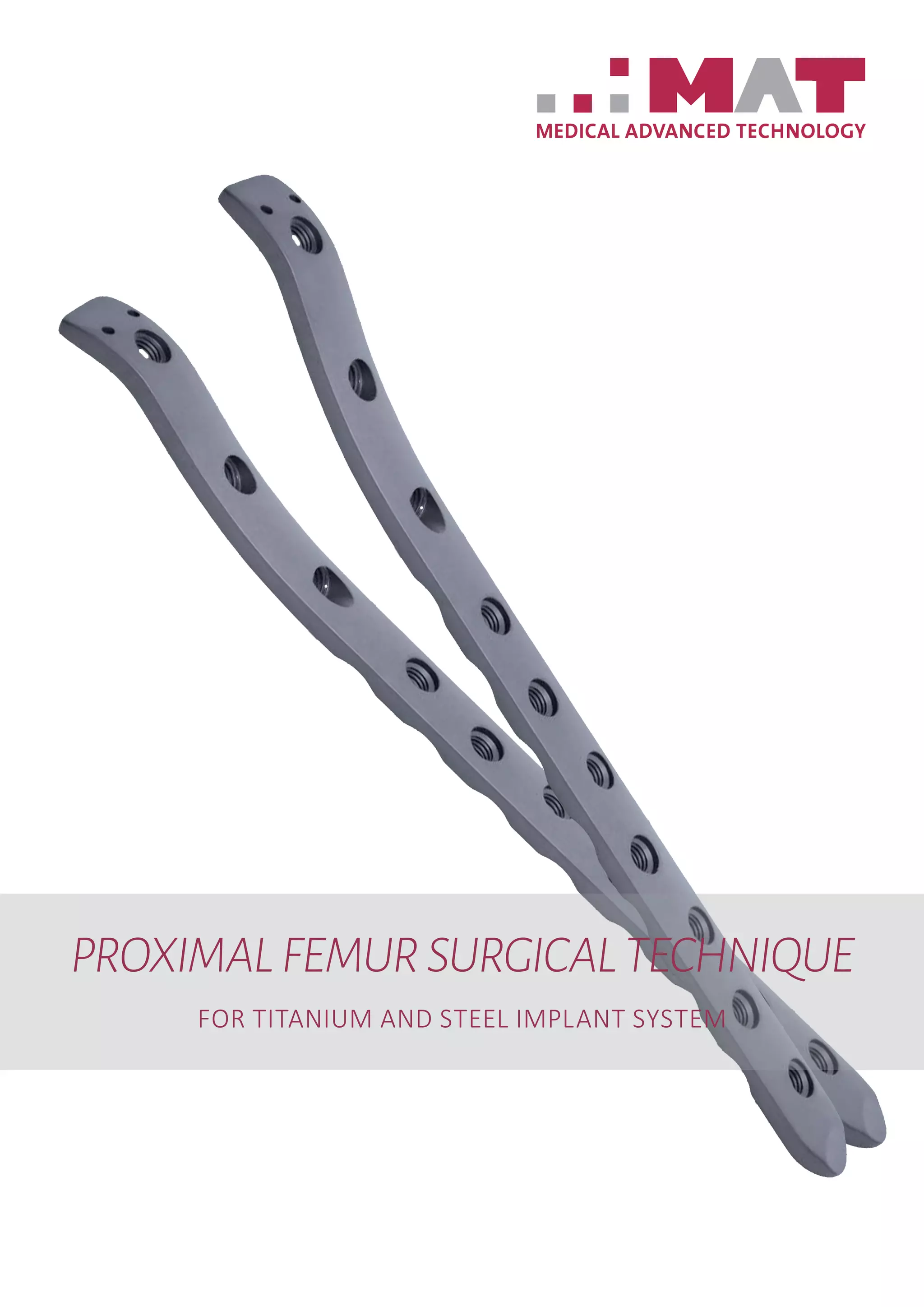
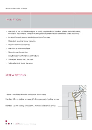
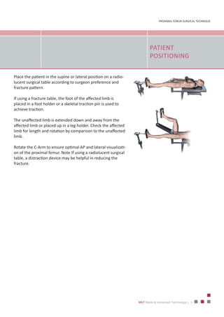
PROXIMALFEMURSURGICALTECHNIQUE
FOR TITANIUM AND STEEL IMPLANT SYSTEM
PROXIMAL FEMUR SURGICAL TECHNIQUE
2 | MAT Medical Advanced Technology
MAT– a committed specialist
that cares for clinical resources
Specialized in the fields of orthopedics, traumatology and spinal
column, MAT innovative products and solutions, from which you as
a dealer benefit just like the respectively responsible doctor or the
OP personnel and - beyond the economic and administrative aspect -
clinic management as well.
The excellent quality and precision of our products, as well as the
willingness to adapt our developments exclusively to your
requirements, are the most important elements of our offered
products and services.
Our product ideas help you to preserve the most precious resources
of daily clinic operations: Nerves, time and money.
3
PROXIMAL FEMUR SURGICAL TECHNIQUE
MAT Medical Advanced Technology |
LARGE FRAGMENT
LOCKING INSTRU-
MENT SET OVERVIEW
PROXIMAL FEMUR SURGICAL TECHNIQUE
4 | MAT Medical Advanced Technology
INDICATIONS
•	 Fractures of the trochanteric region including simple intertrochanteric, reverse intertrochanteric,
transverse trochanteric, complex multifragmentary and fractures with medial cortex instability
•	 Proximal femur fractures with ipsilateral shaft fractures
•	 Metastatic proximal femur fractures
•	 Proximal femur osteotomies
•	 Fractures in osteopenic bone
•	 Nonunions and malunions
•	 Basi/transcervical femoral neck fractures
•	 Subcapital femoral neck fractures
•	 Subtrochanteric femur fractures
SCREW OPTIONS
7.3 mm cannulated threaded and conical head screws
Standard 5.0 mm locking screws and 5.0mm cannulated locking screws
Standard 5.0 mm locking screws or 4.5 mm standard cortex screws
5
PROXIMAL FEMUR SURGICAL TECHNIQUE
MAT Medical Advanced Technology |
PATIENT
POSITIONING
Place the patient in the supine or lateral position on a radio‐
lucent surgical table according to surgeon preference and
fracture pattern.
If using a fracture table, the foot of the affected limb is
placed in a foot holder or a skeletal traction pin is used to
achieve traction.
The unaffected limb is extended down and away from the
affected limb or placed up in a leg holder. Check the affected
limb for length and rotation by comparison to the unaffected
limb.
Rotate the C‐Arm to ensure optimal AP and lateral visualizati‐
on of the proximal femur. Note If using a radiolucent surgical
table, a distraction device may be helpful in reducing the
fracture.
PROXIMAL FEMUR SURGICAL TECHNIQUE
6 | MAT Medical Advanced Technology
SURGICAL TECHNIQUE
Step 1
Insert the wire and determain the path of the screw,
screw the drill sleeves into the first 3 proximal holes.
Use Drill sleeve 7.3 mm (3‐3521) in combination with
wire sleeve 2.5 mm (3‐3519) for the first 2 holes, Drill
sleeve 5.0 mm for the third hole.
Use the drill sleeves to hold and position the plate on
the proximal femur.
Insert a guide wire (004‐0740‐0166) through the wire
guide in each of the three proximal locking holes.
Note: For proper screw measurement, guide wires
should not penetrate subchondral bone.
Step 2
Measure correct screw length,
use the direct measuring device (3‐3523) to measure
screw length.
Place the measuring device over the guide wire.
Select the appropriate length 7.3 mm cannulated locking
screw.
Note: The screws have self‐drilling, self‐tapping flutes.
In case of dense bone use:
‐ drill bit 5.5 mm for 7.3 mm screws (3‐3525)
‐ drill bit 4.3 mm for 5.0 mm screws (3‐3505)
7
PROXIMAL FEMUR SURGICAL TECHNIQUE
MAT Medical Advanced Technology |
SURGICAL TECHNIQUE
Step 3
Insert the screws,
with the large screw driver (009‐0368‐035) using
fluoroscopy.
Once the screw has been locked to the plate, the guide
wire may be removed.
Note: Recheck each locking screw prior to closing to
verify that the screws are securely locked to the plate.
If plates needs to be compressed to the bone use a
fully threaded 7.3 mm cannulated conical screw in the
proximal screw hole.
Insert the second screw by following the same steps.
Precaution: Angular stability can only be achieved by
using locking screws. In such case replace the conical
screws with a locking screws.
Step 4
Approximate the plate to the femoral diaphysis,
use a bone holding forceps to secure the plate to the
bone.
Adjust rotation as required.
Reduce fracture and restore length with appropriate me‐
ans (fracture table, the Articulated Tension Device, etc.).
If appropriate use the tension device at the end of the
plate to compress the fracture.
Note: Tension the plate, and compress the fracture
creates a load‐sharing construct. Alternatively, although
less desirable, the plate can be used as a bridging con-
struct in patterns with segmental comminution where
plate tensioning cannot be accomplished.
PROXIMAL FEMUR SURGICAL TECHNIQUE
8 | MAT Medical Advanced Technology
SURGICAL TECHNIQUE
Step 6
Measuring and 4.5mm cortex screw insertion,
measure for screw length using the depth gauge
(005‐0219‐006).
Select and insert the appropriate length 4.5 mm cortex
screw using the screwdriver (009‐0368‐035).
Insert as many standard 4.5 mm cortex screws as
necessary.
Step 5
4.5 mm Cortex screw insertion,
use a 3.2 mm drill bit (005‐0210‐031) and drill through
the universal drill guide (005‐0222‐025) to predrill the
bone.
To achieve compression, place the universal drill guide
at the end of the non‐threaded hole away from the frac‐
ture (do not apply downward pressure on the spring‐
loaded tip).
Notes : All 4.5 mm cortex screws must be inserted into
the plate shaft before locking screws are inserted into
the plate shaft.
9
PROXIMAL FEMUR SURGICAL TECHNIQUE
MAT Medical Advanced Technology |
SURGICAL TECHNIQUE
Step 8
Insert 5.0 mm cannulated locking screw,
using the wire guide and guide wire previously inserted at
this hole location, measure for the screw length with the
measuring device.
The correct length measurement will place the screw at the
tip of the guide wire.
Remove the wire guide and insert the appropriate length
screw over the guide wire and into the bone using the tor‐
que limiting screwdriver (3‐3513).
Precautions – The need for this screw is fracture configurati‐
on dependent and should be determined during preoperati‐
ve planning. – Securely tighten all locking screws again prior
to closing.
Step 7
Locking screw insertion,
attach the 4.3 mm drill sleeve (3‐3509) to the threaded
portion of a hole in the plate shaft.
Carefully drill the screw hole using the 4.3 mm drill bit
(3‐3505).
Read the drilled depth directly from the laser mark on
the drill bit or determine the screw length with the
depth gauge.
Insert the appropriate length 5.0 mm locking screw
using the 3.5mm torque limiting screw driver (3‐3513).
Note : After one click, the optimum (4NM) torque is
reached.
MAT GmbH & C o.KG
Friedrich-Wöhler Straße 10
78576 Emmingen-Liptingen | Germany
Phone: +49 7465 909-188 ∙ Fax : +49 7465 909-024
www.mat-medical.com · info@mat-medical.com
REV. 31.05.2017
MAT GmbH&Co.KG_Copyright_Germany

MAT - Proximal Femur Plate

  • 1.
  • 2.
    PROXIMAL FEMUR SURGICALTECHNIQUE 2 | MAT Medical Advanced Technology MAT– a committed specialist that cares for clinical resources Specialized in the fields of orthopedics, traumatology and spinal column, MAT innovative products and solutions, from which you as a dealer benefit just like the respectively responsible doctor or the OP personnel and - beyond the economic and administrative aspect - clinic management as well. The excellent quality and precision of our products, as well as the willingness to adapt our developments exclusively to your requirements, are the most important elements of our offered products and services. Our product ideas help you to preserve the most precious resources of daily clinic operations: Nerves, time and money.
  • 3.
    3 PROXIMAL FEMUR SURGICALTECHNIQUE MAT Medical Advanced Technology | LARGE FRAGMENT LOCKING INSTRU- MENT SET OVERVIEW
  • 4.
    PROXIMAL FEMUR SURGICALTECHNIQUE 4 | MAT Medical Advanced Technology INDICATIONS • Fractures of the trochanteric region including simple intertrochanteric, reverse intertrochanteric, transverse trochanteric, complex multifragmentary and fractures with medial cortex instability • Proximal femur fractures with ipsilateral shaft fractures • Metastatic proximal femur fractures • Proximal femur osteotomies • Fractures in osteopenic bone • Nonunions and malunions • Basi/transcervical femoral neck fractures • Subcapital femoral neck fractures • Subtrochanteric femur fractures SCREW OPTIONS 7.3 mm cannulated threaded and conical head screws Standard 5.0 mm locking screws and 5.0mm cannulated locking screws Standard 5.0 mm locking screws or 4.5 mm standard cortex screws
  • 5.
    5 PROXIMAL FEMUR SURGICALTECHNIQUE MAT Medical Advanced Technology | PATIENT POSITIONING Place the patient in the supine or lateral position on a radio‐ lucent surgical table according to surgeon preference and fracture pattern. If using a fracture table, the foot of the affected limb is placed in a foot holder or a skeletal traction pin is used to achieve traction. The unaffected limb is extended down and away from the affected limb or placed up in a leg holder. Check the affected limb for length and rotation by comparison to the unaffected limb. Rotate the C‐Arm to ensure optimal AP and lateral visualizati‐ on of the proximal femur. Note If using a radiolucent surgical table, a distraction device may be helpful in reducing the fracture.
  • 6.
    PROXIMAL FEMUR SURGICALTECHNIQUE 6 | MAT Medical Advanced Technology SURGICAL TECHNIQUE Step 1 Insert the wire and determain the path of the screw, screw the drill sleeves into the first 3 proximal holes. Use Drill sleeve 7.3 mm (3‐3521) in combination with wire sleeve 2.5 mm (3‐3519) for the first 2 holes, Drill sleeve 5.0 mm for the third hole. Use the drill sleeves to hold and position the plate on the proximal femur. Insert a guide wire (004‐0740‐0166) through the wire guide in each of the three proximal locking holes. Note: For proper screw measurement, guide wires should not penetrate subchondral bone. Step 2 Measure correct screw length, use the direct measuring device (3‐3523) to measure screw length. Place the measuring device over the guide wire. Select the appropriate length 7.3 mm cannulated locking screw. Note: The screws have self‐drilling, self‐tapping flutes. In case of dense bone use: ‐ drill bit 5.5 mm for 7.3 mm screws (3‐3525) ‐ drill bit 4.3 mm for 5.0 mm screws (3‐3505)
  • 7.
    7 PROXIMAL FEMUR SURGICALTECHNIQUE MAT Medical Advanced Technology | SURGICAL TECHNIQUE Step 3 Insert the screws, with the large screw driver (009‐0368‐035) using fluoroscopy. Once the screw has been locked to the plate, the guide wire may be removed. Note: Recheck each locking screw prior to closing to verify that the screws are securely locked to the plate. If plates needs to be compressed to the bone use a fully threaded 7.3 mm cannulated conical screw in the proximal screw hole. Insert the second screw by following the same steps. Precaution: Angular stability can only be achieved by using locking screws. In such case replace the conical screws with a locking screws. Step 4 Approximate the plate to the femoral diaphysis, use a bone holding forceps to secure the plate to the bone. Adjust rotation as required. Reduce fracture and restore length with appropriate me‐ ans (fracture table, the Articulated Tension Device, etc.). If appropriate use the tension device at the end of the plate to compress the fracture. Note: Tension the plate, and compress the fracture creates a load‐sharing construct. Alternatively, although less desirable, the plate can be used as a bridging con- struct in patterns with segmental comminution where plate tensioning cannot be accomplished.
  • 8.
    PROXIMAL FEMUR SURGICALTECHNIQUE 8 | MAT Medical Advanced Technology SURGICAL TECHNIQUE Step 6 Measuring and 4.5mm cortex screw insertion, measure for screw length using the depth gauge (005‐0219‐006). Select and insert the appropriate length 4.5 mm cortex screw using the screwdriver (009‐0368‐035). Insert as many standard 4.5 mm cortex screws as necessary. Step 5 4.5 mm Cortex screw insertion, use a 3.2 mm drill bit (005‐0210‐031) and drill through the universal drill guide (005‐0222‐025) to predrill the bone. To achieve compression, place the universal drill guide at the end of the non‐threaded hole away from the frac‐ ture (do not apply downward pressure on the spring‐ loaded tip). Notes : All 4.5 mm cortex screws must be inserted into the plate shaft before locking screws are inserted into the plate shaft.
  • 9.
    9 PROXIMAL FEMUR SURGICALTECHNIQUE MAT Medical Advanced Technology | SURGICAL TECHNIQUE Step 8 Insert 5.0 mm cannulated locking screw, using the wire guide and guide wire previously inserted at this hole location, measure for the screw length with the measuring device. The correct length measurement will place the screw at the tip of the guide wire. Remove the wire guide and insert the appropriate length screw over the guide wire and into the bone using the tor‐ que limiting screwdriver (3‐3513). Precautions – The need for this screw is fracture configurati‐ on dependent and should be determined during preoperati‐ ve planning. – Securely tighten all locking screws again prior to closing. Step 7 Locking screw insertion, attach the 4.3 mm drill sleeve (3‐3509) to the threaded portion of a hole in the plate shaft. Carefully drill the screw hole using the 4.3 mm drill bit (3‐3505). Read the drilled depth directly from the laser mark on the drill bit or determine the screw length with the depth gauge. Insert the appropriate length 5.0 mm locking screw using the 3.5mm torque limiting screw driver (3‐3513). Note : After one click, the optimum (4NM) torque is reached.
  • 10.
    MAT GmbH &C o.KG Friedrich-Wöhler Straße 10 78576 Emmingen-Liptingen | Germany Phone: +49 7465 909-188 ∙ Fax : +49 7465 909-024 www.mat-medical.com · info@mat-medical.com REV. 31.05.2017 MAT GmbH&Co.KG_Copyright_Germany