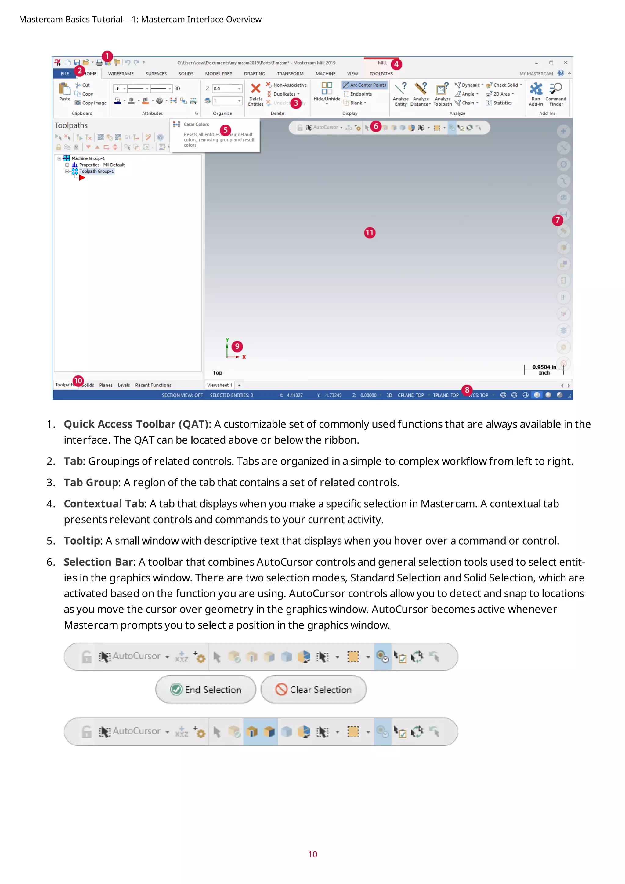
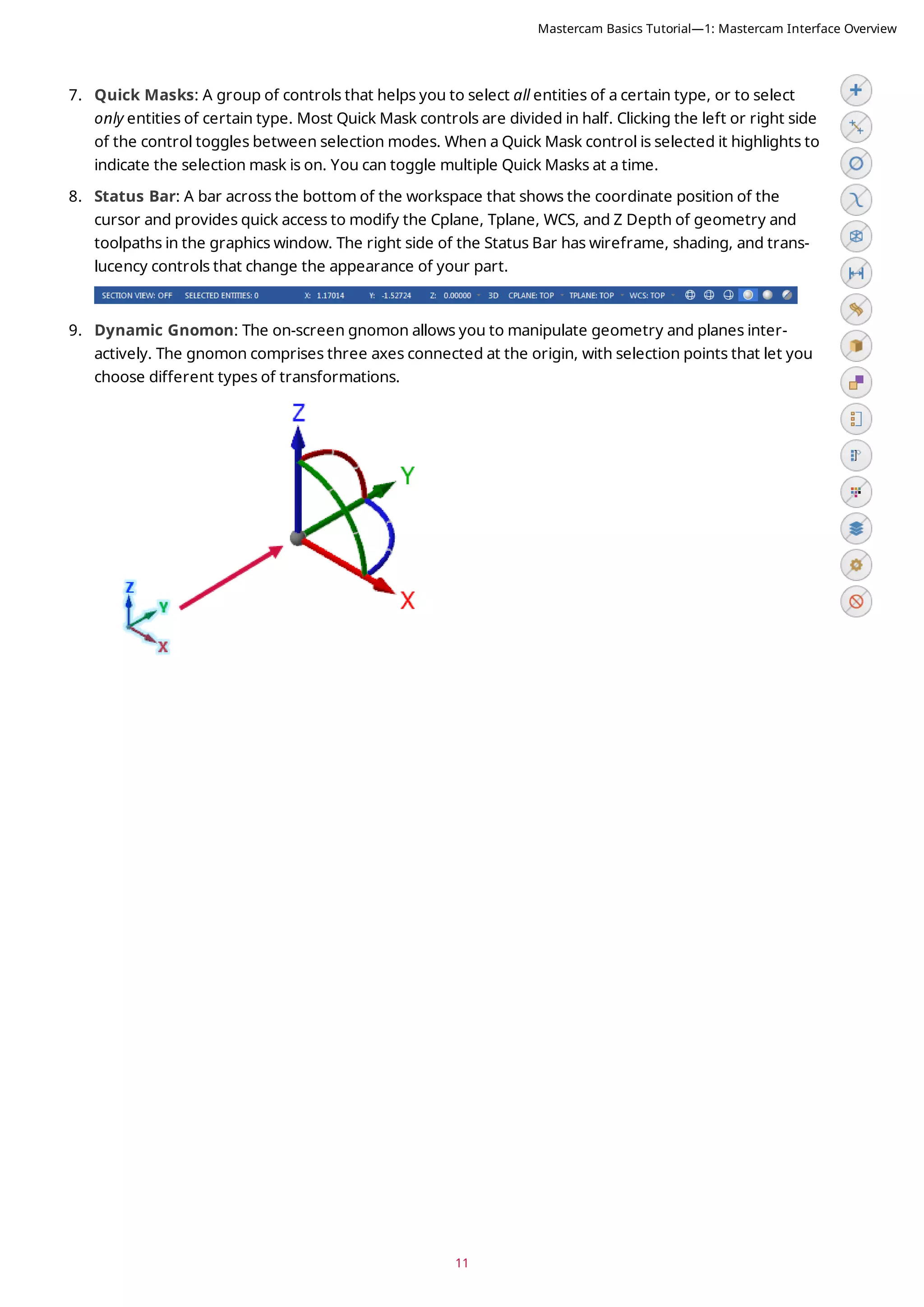
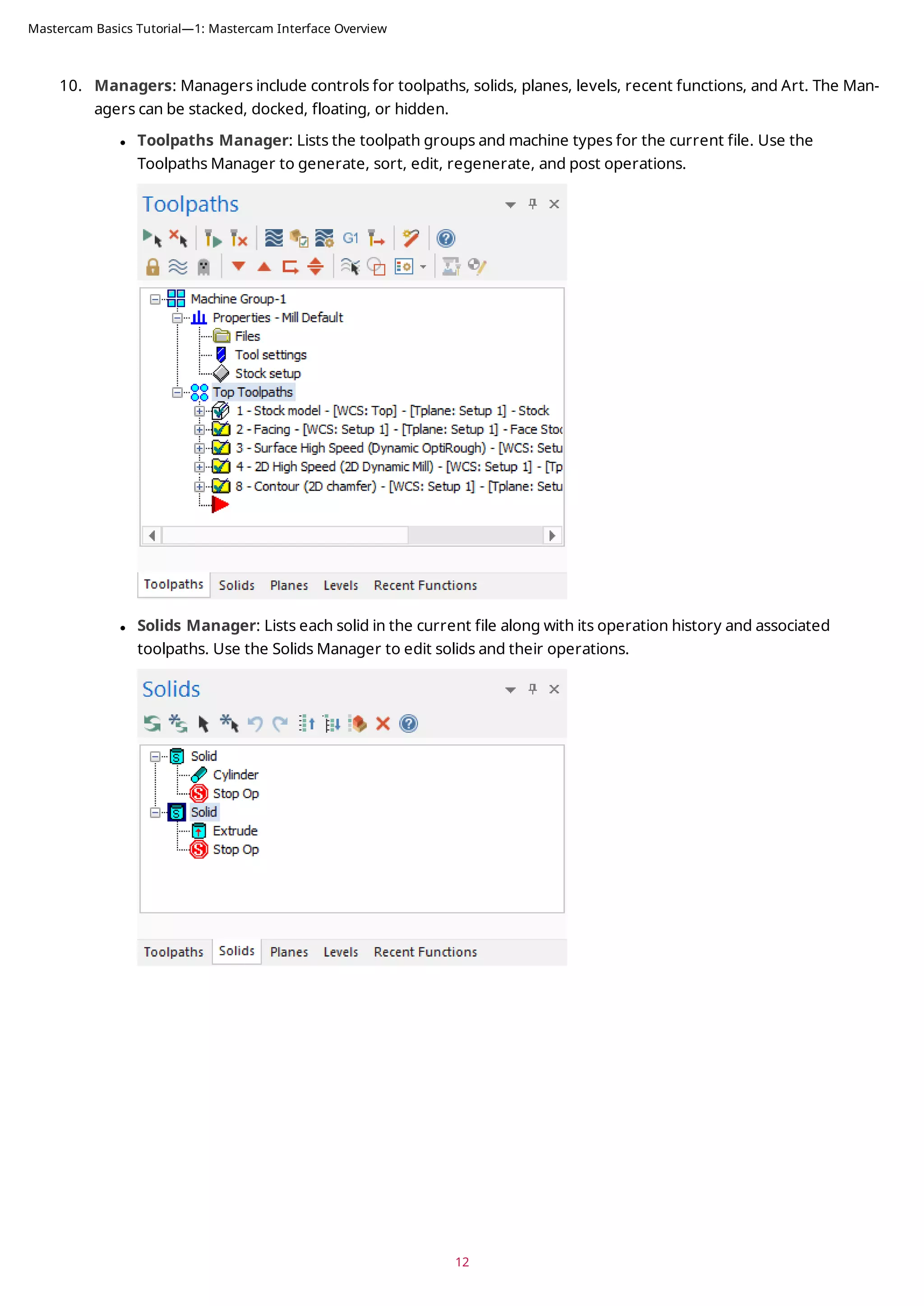
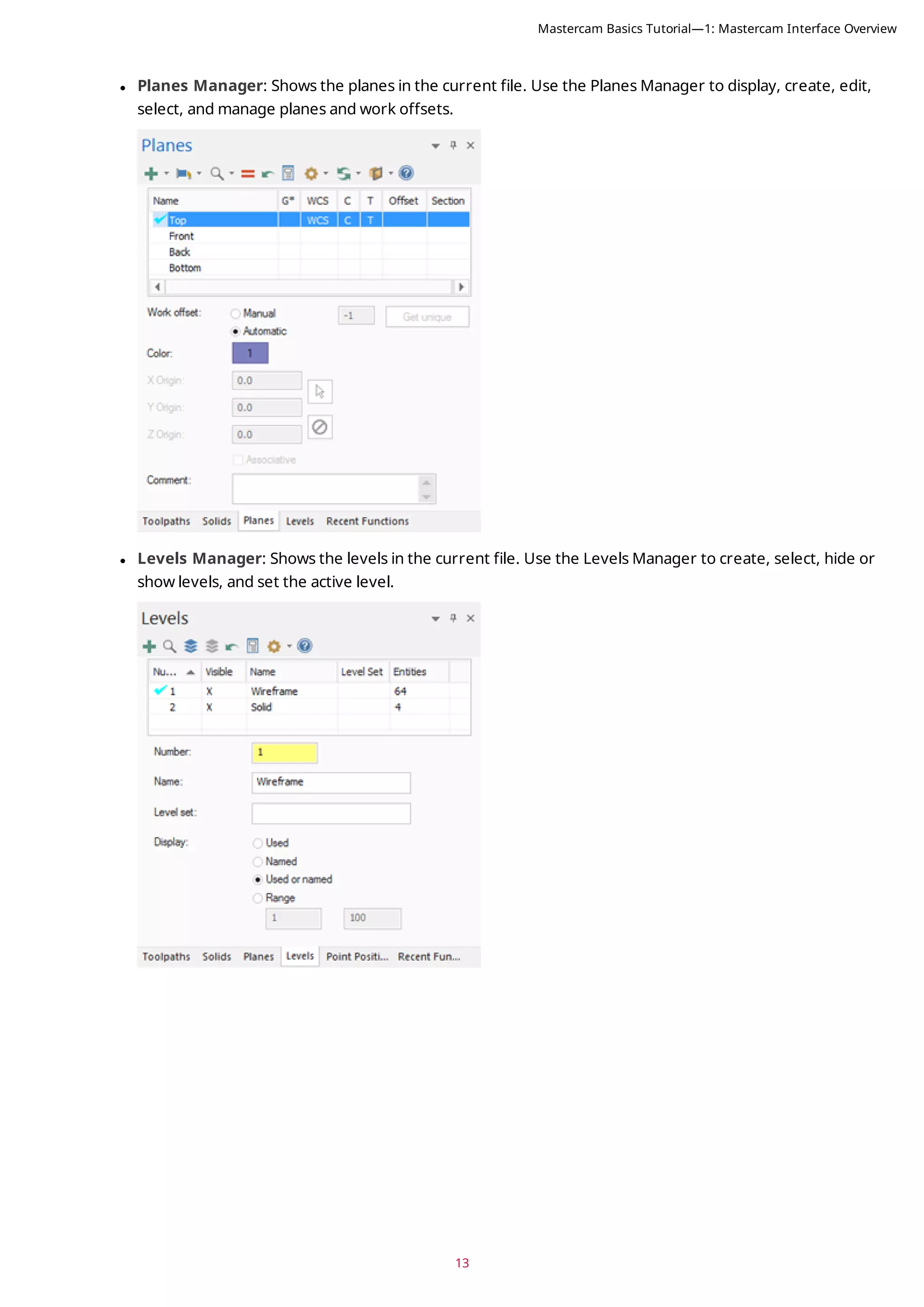
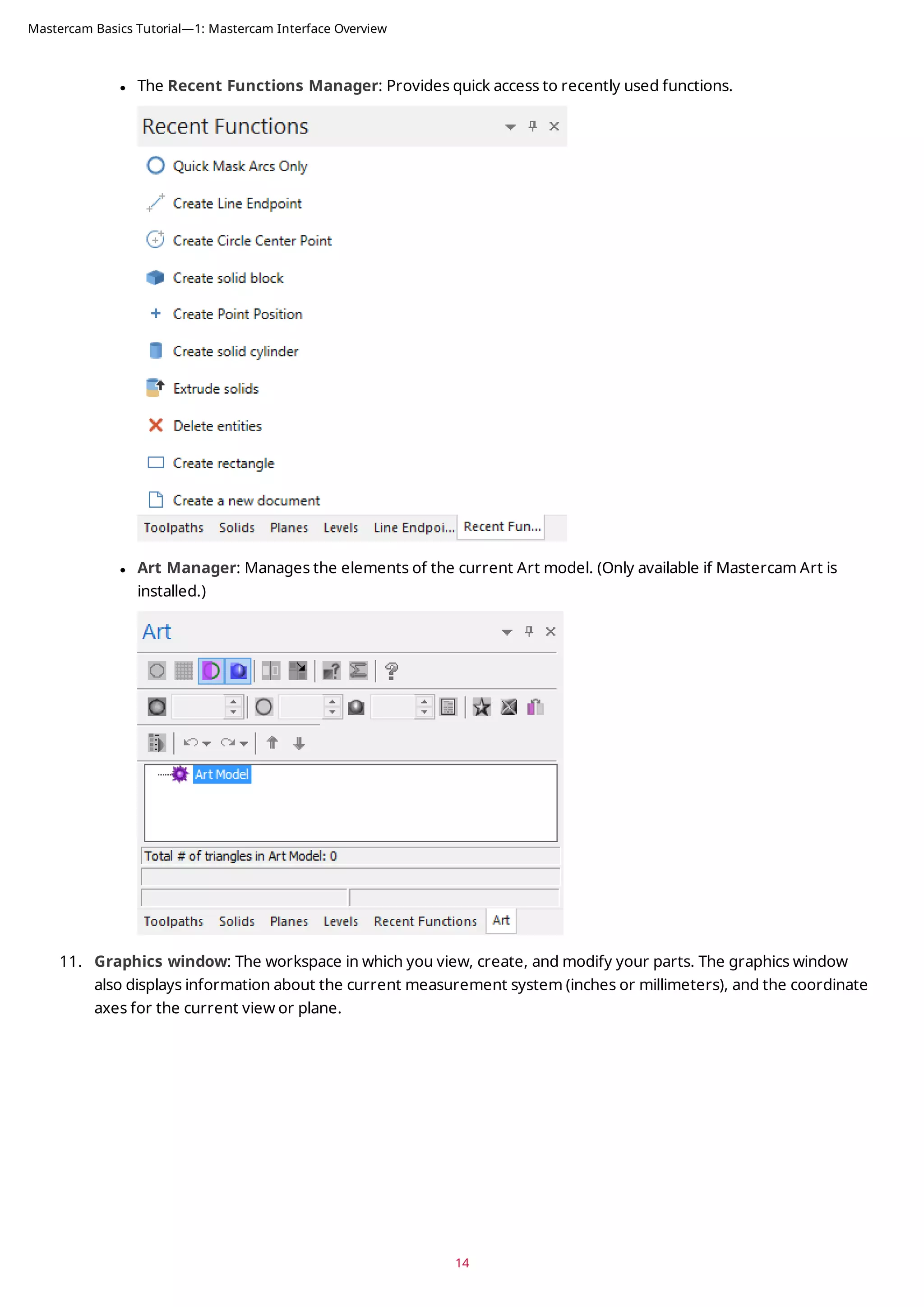
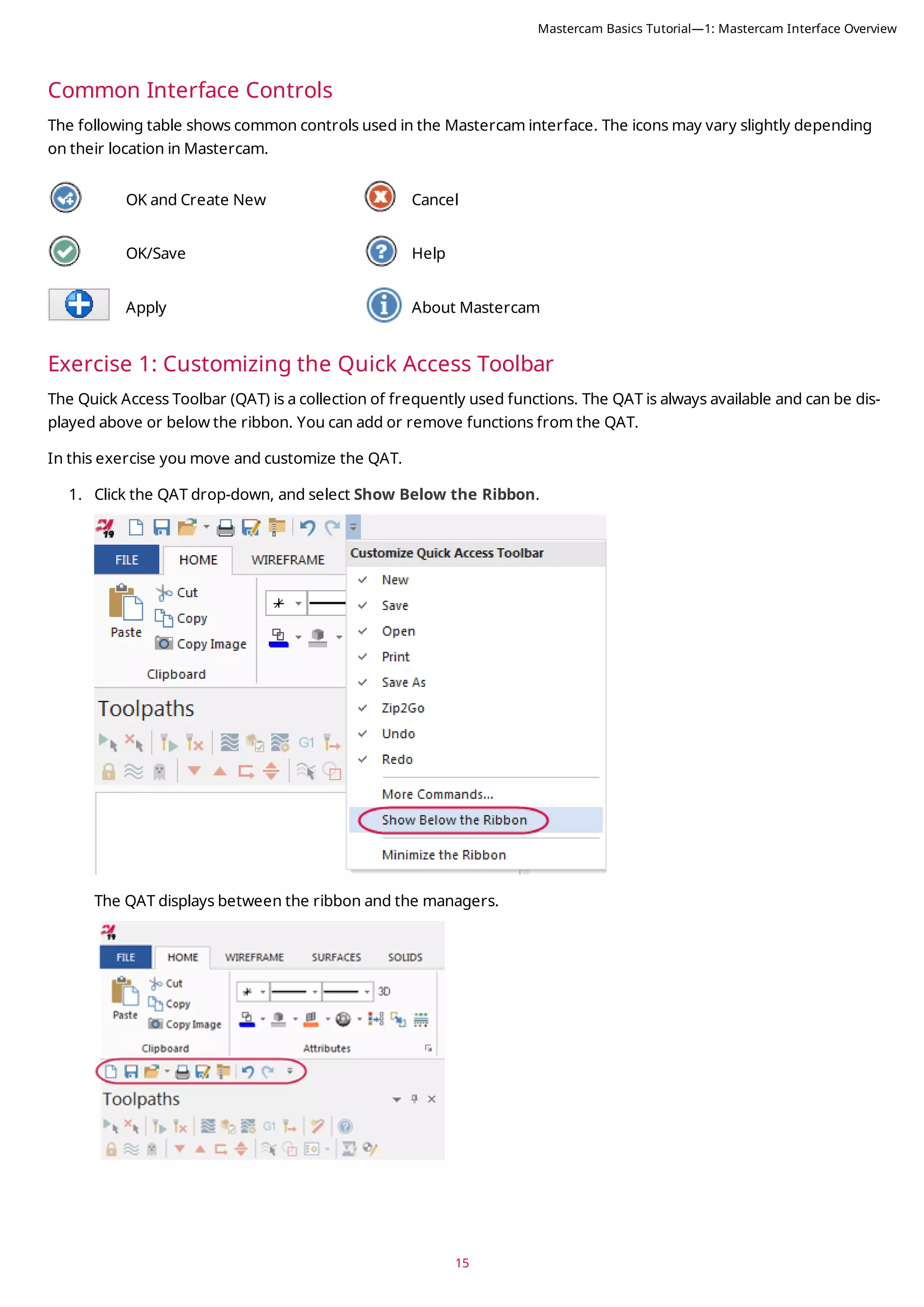
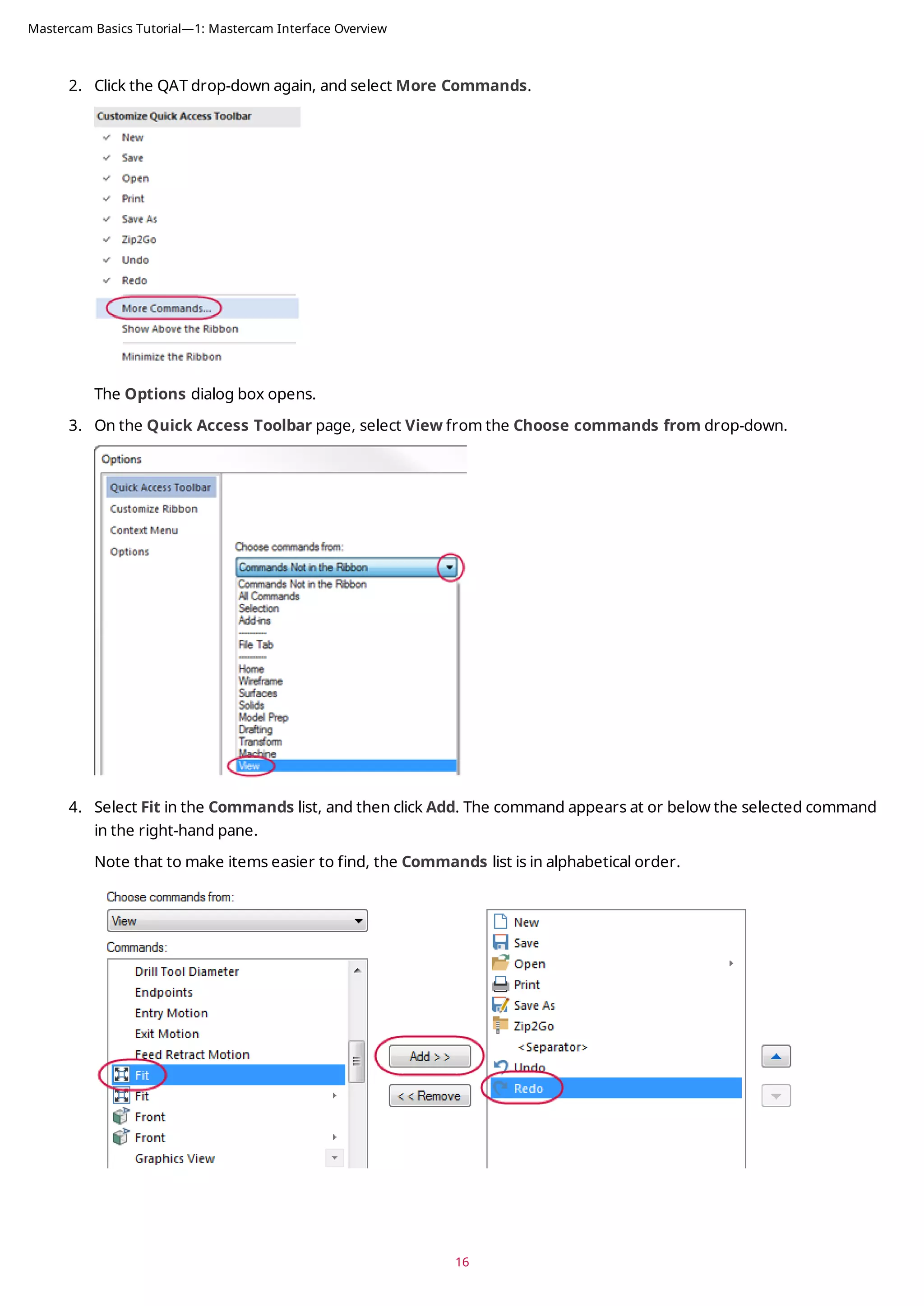
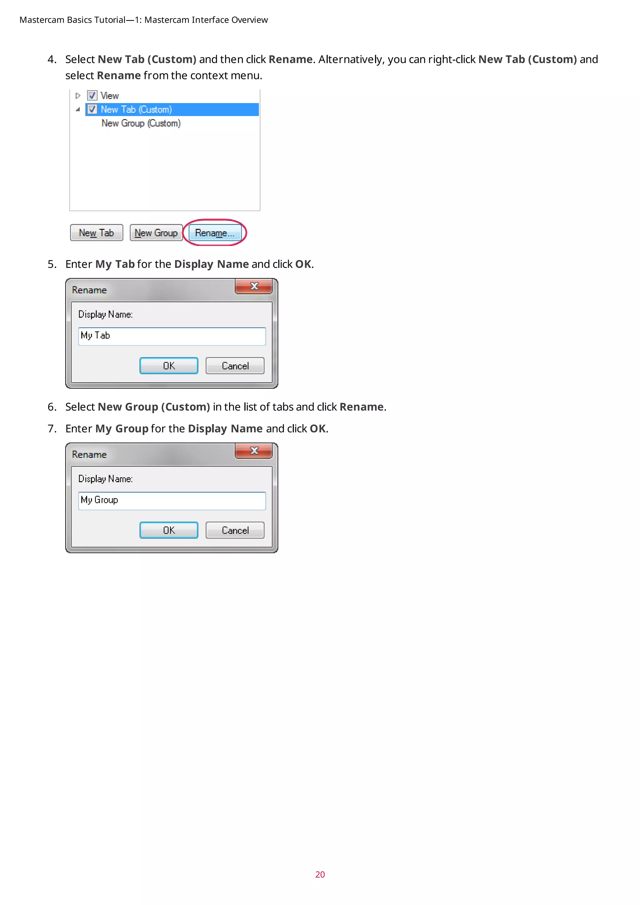
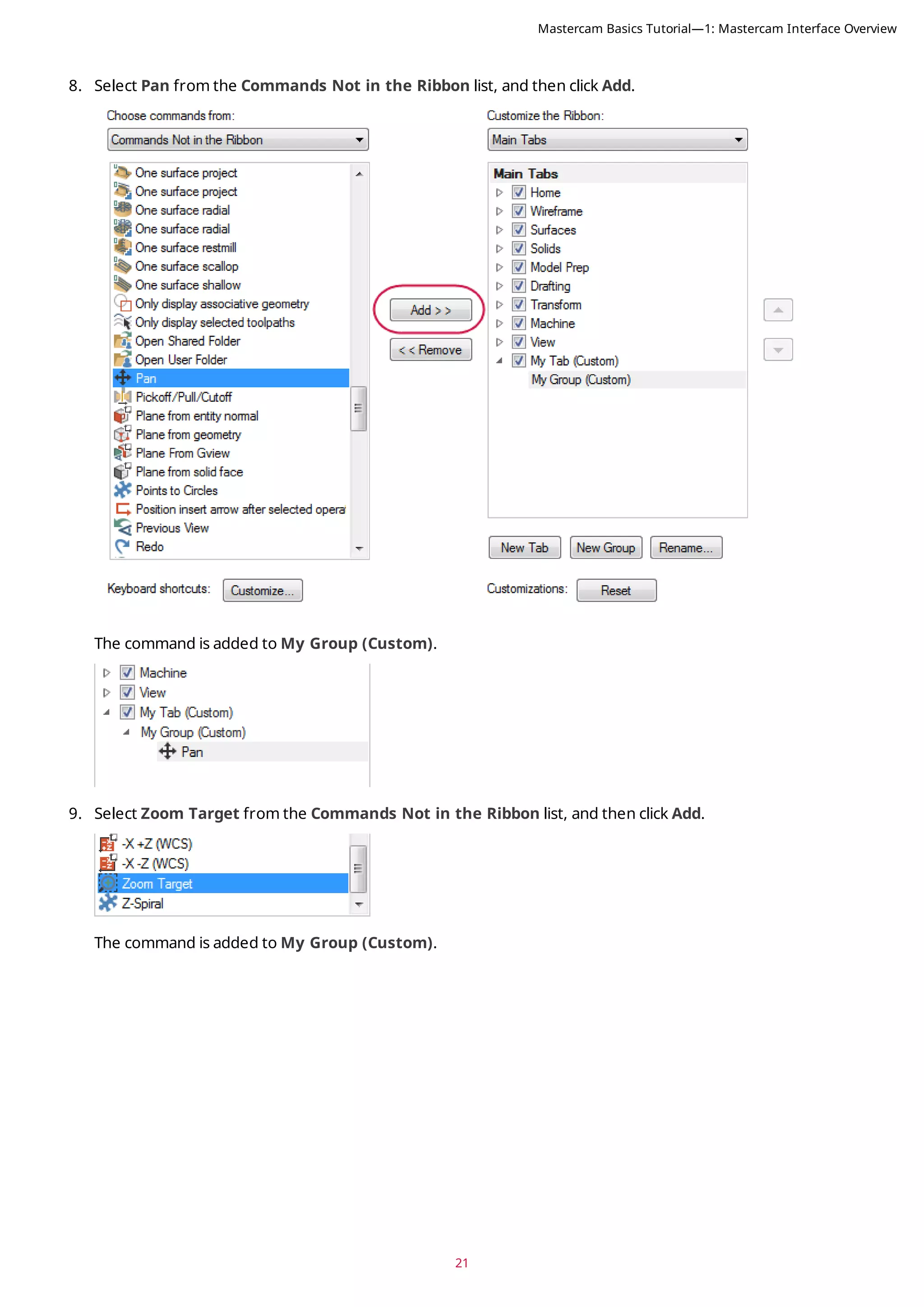
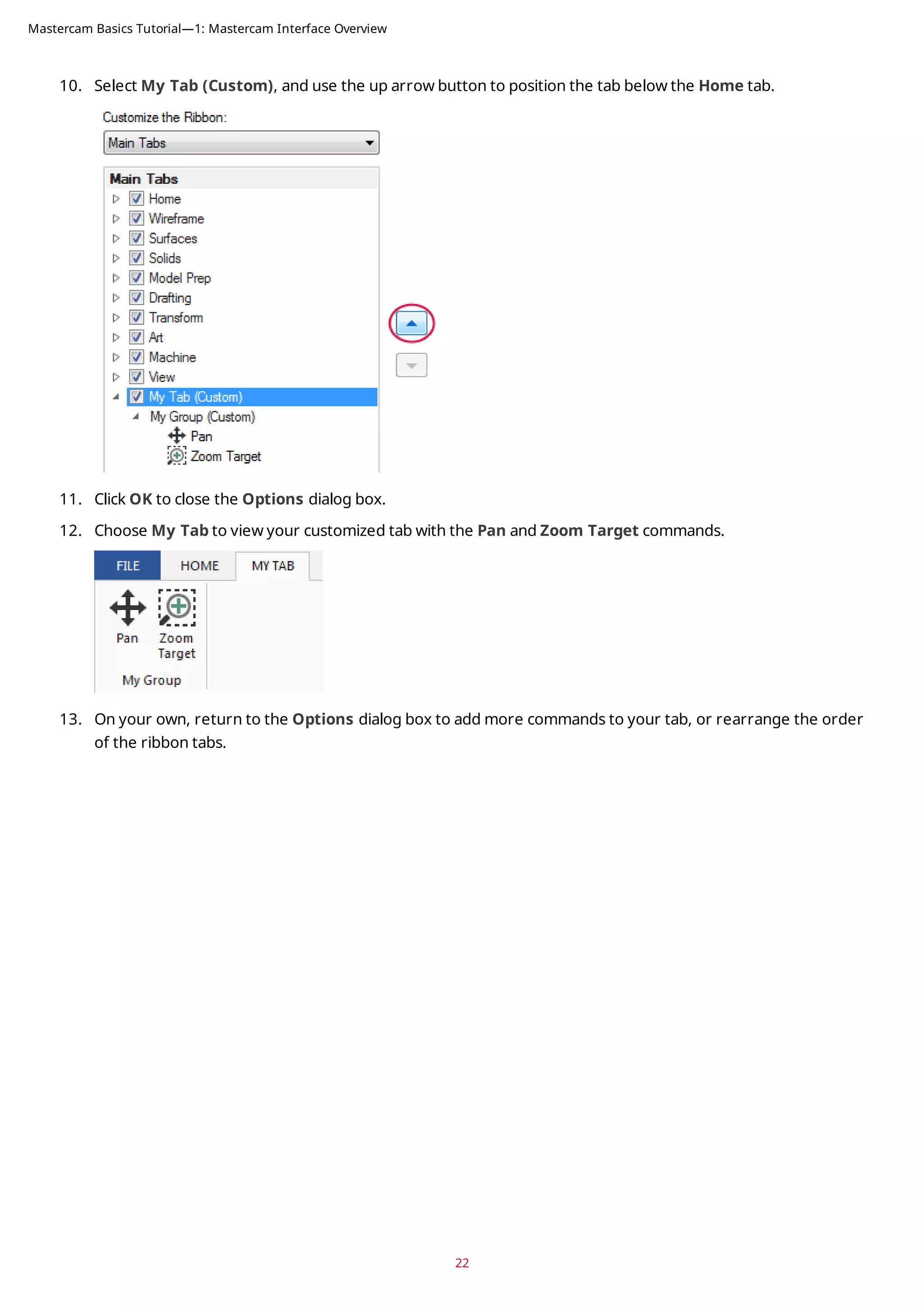
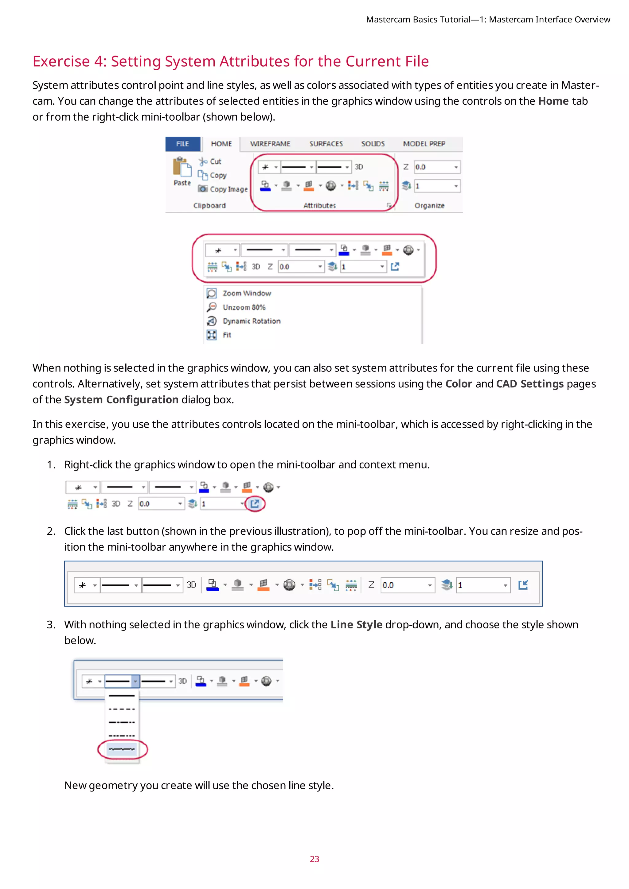
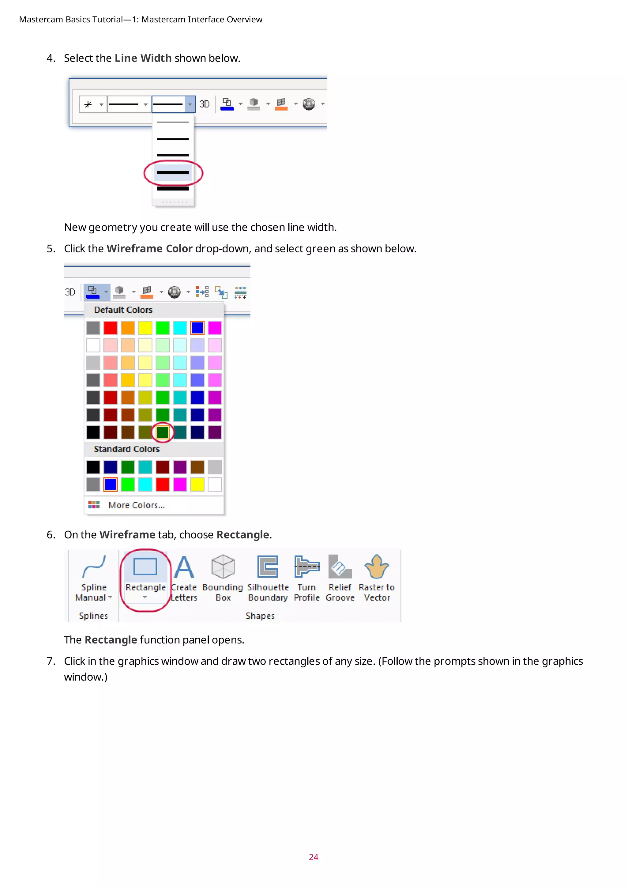
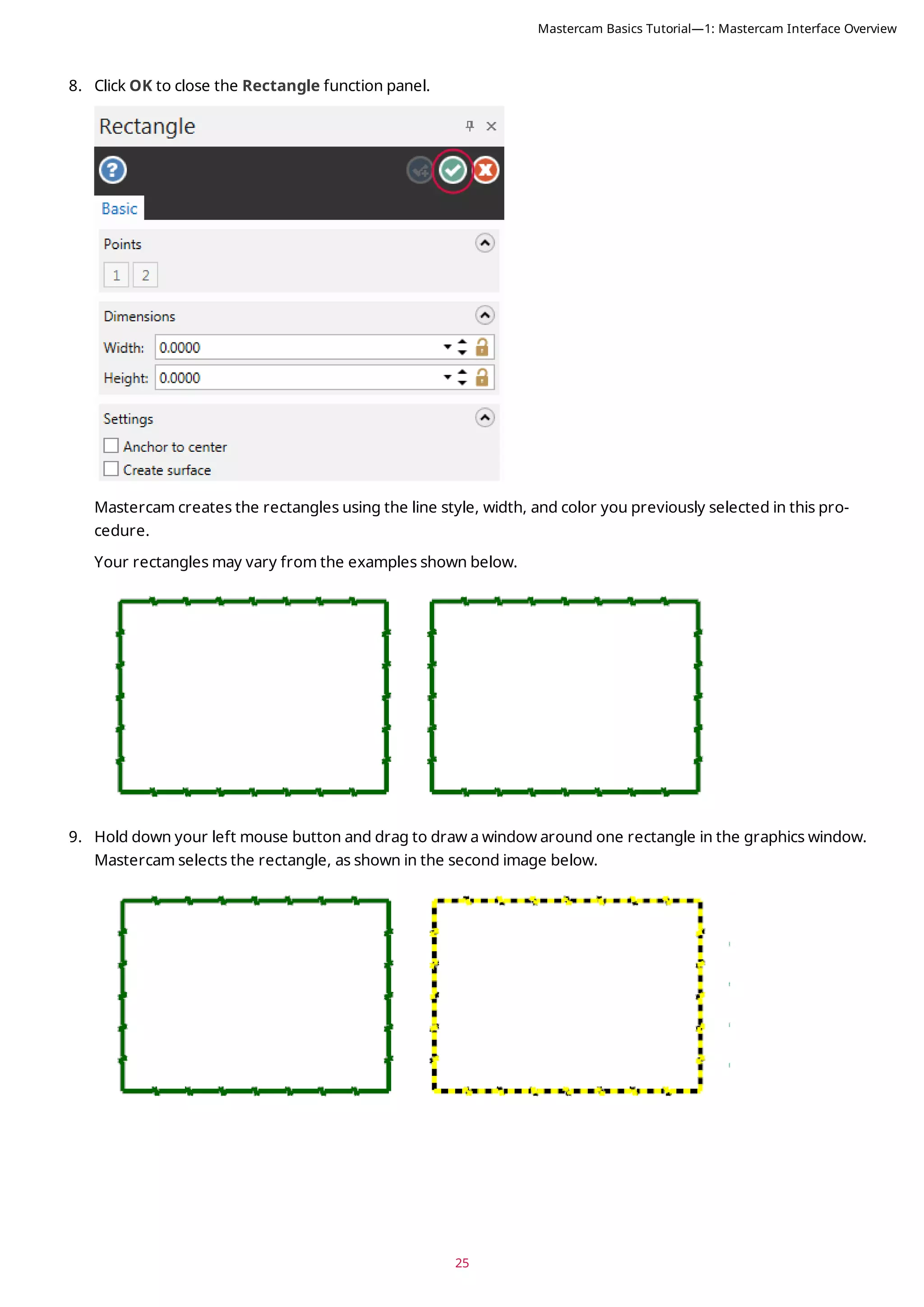
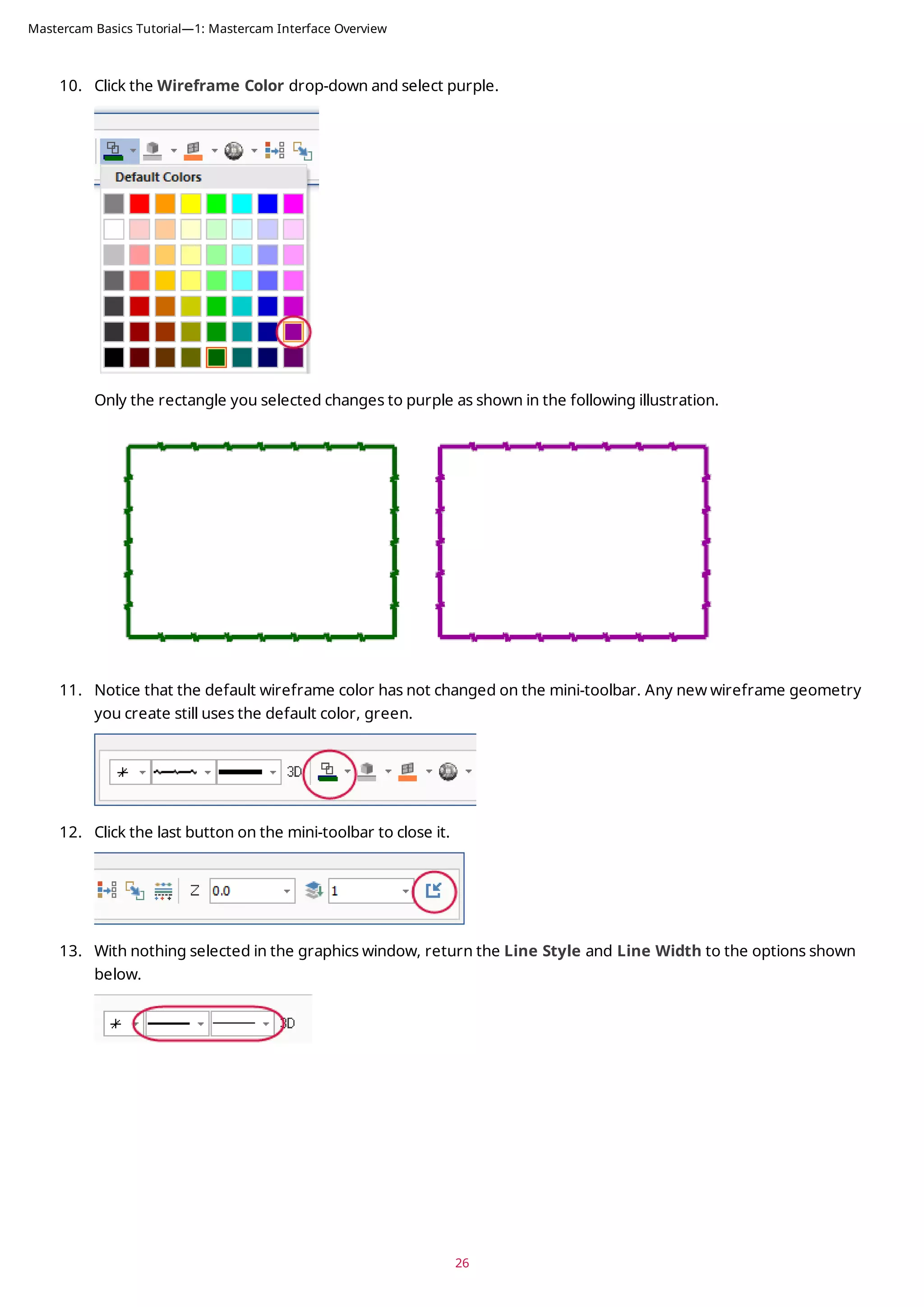
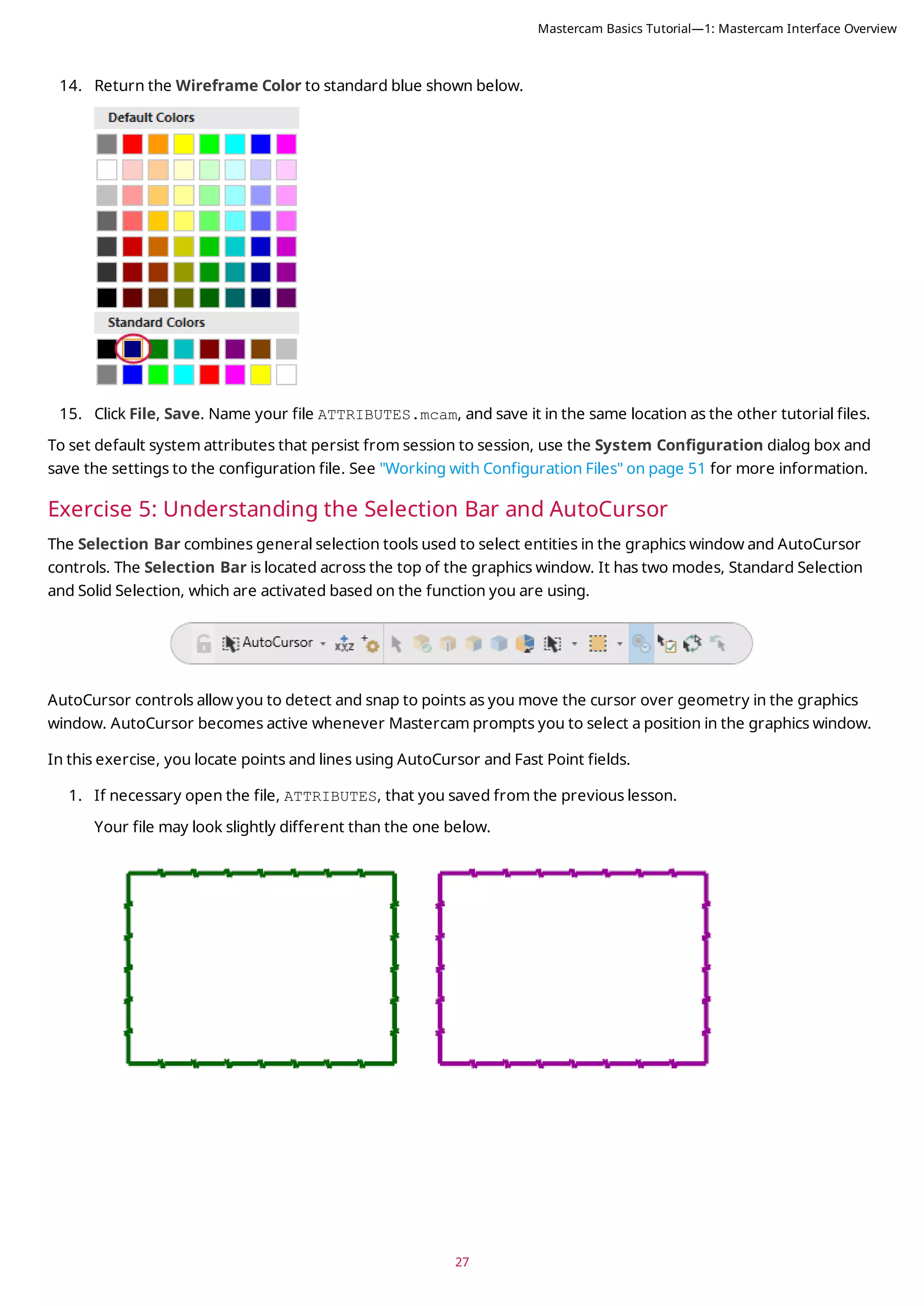
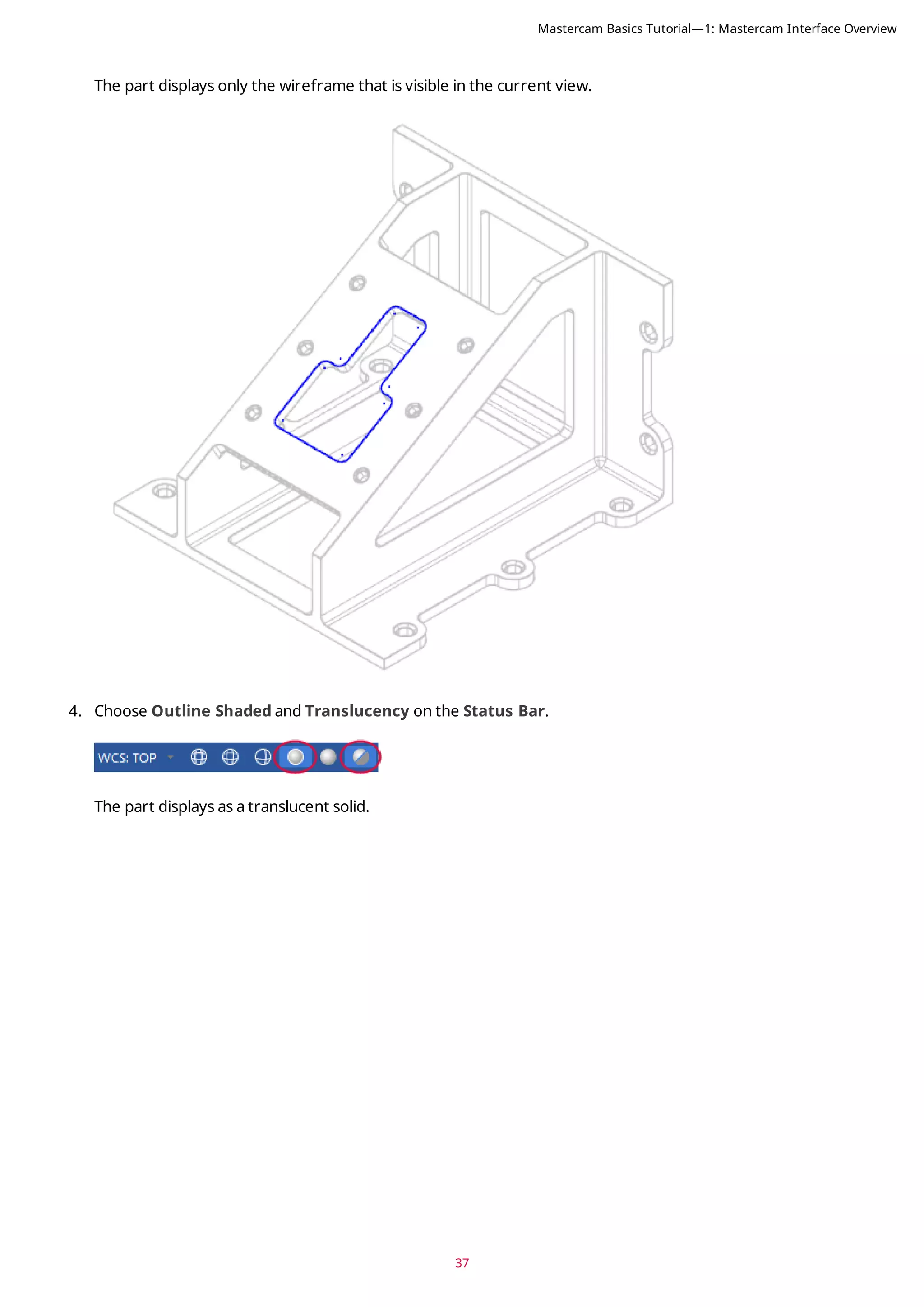
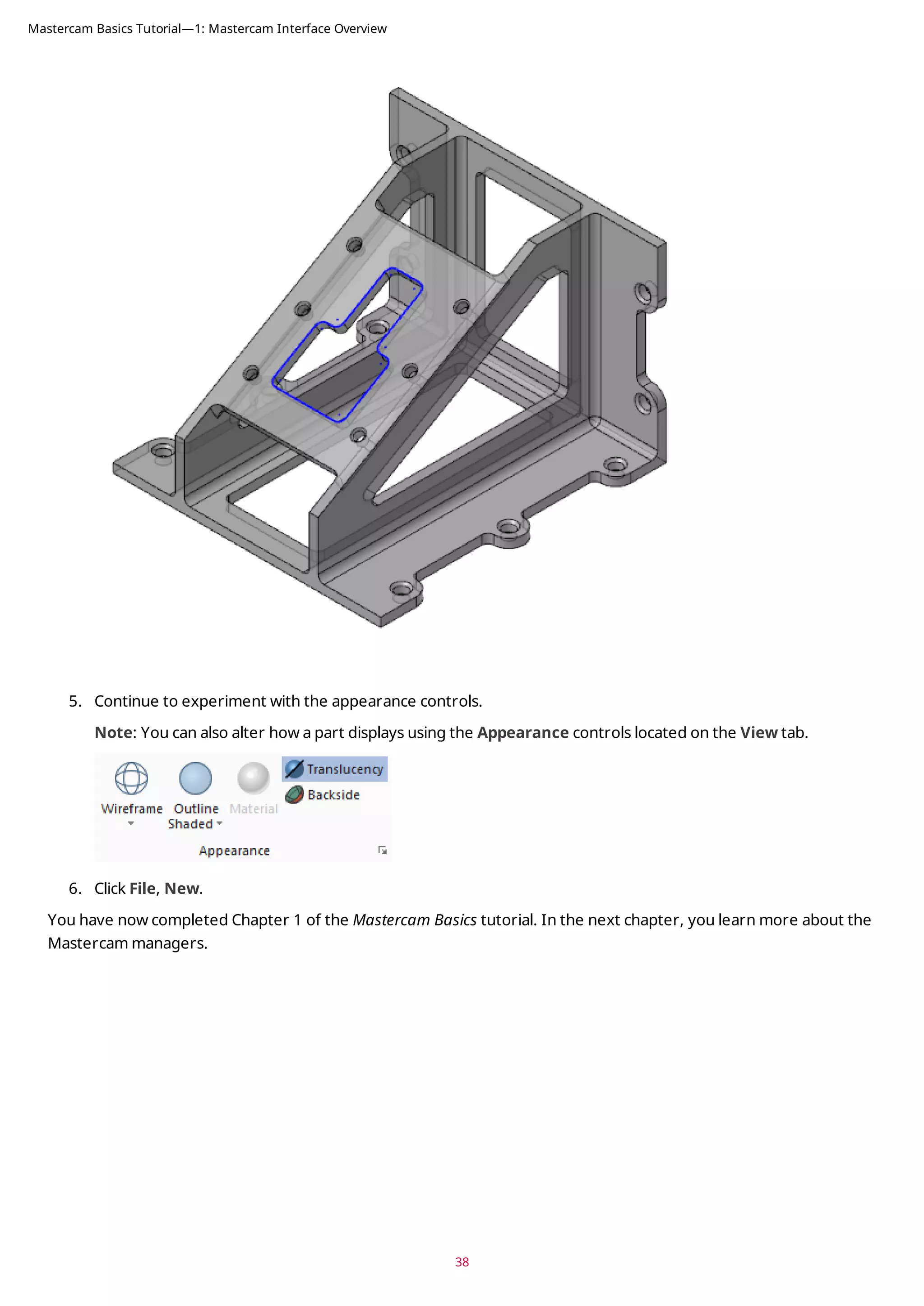
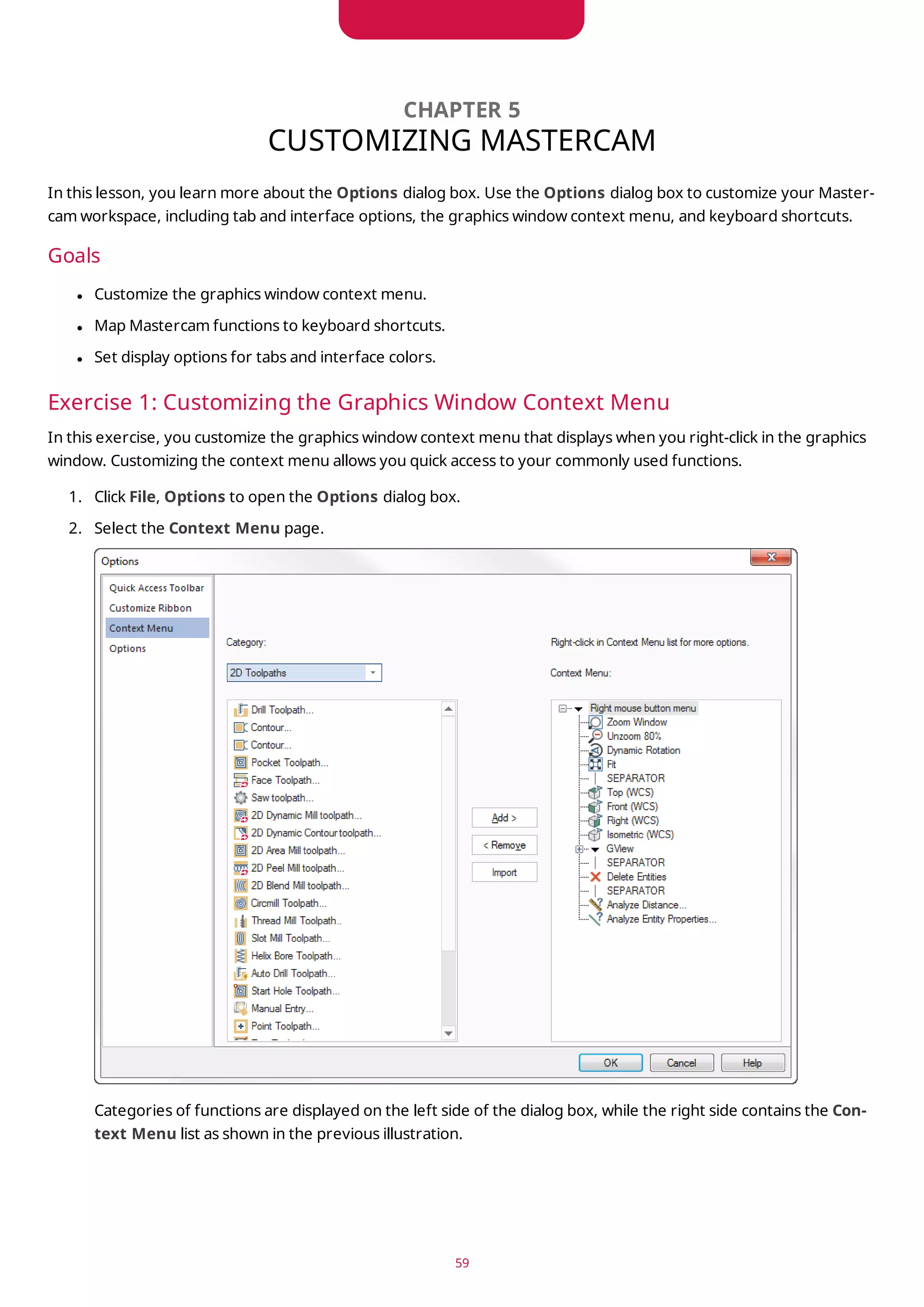
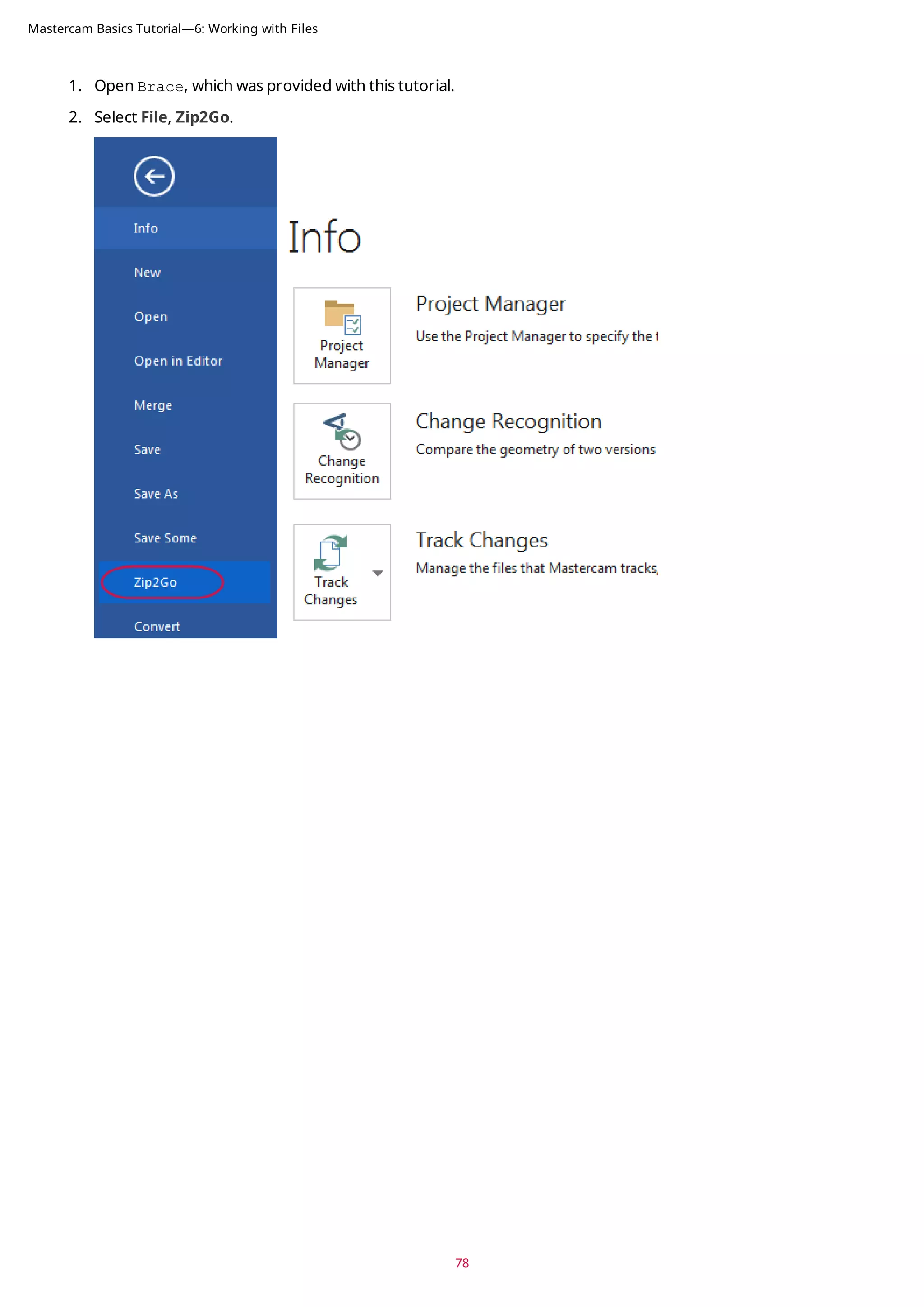
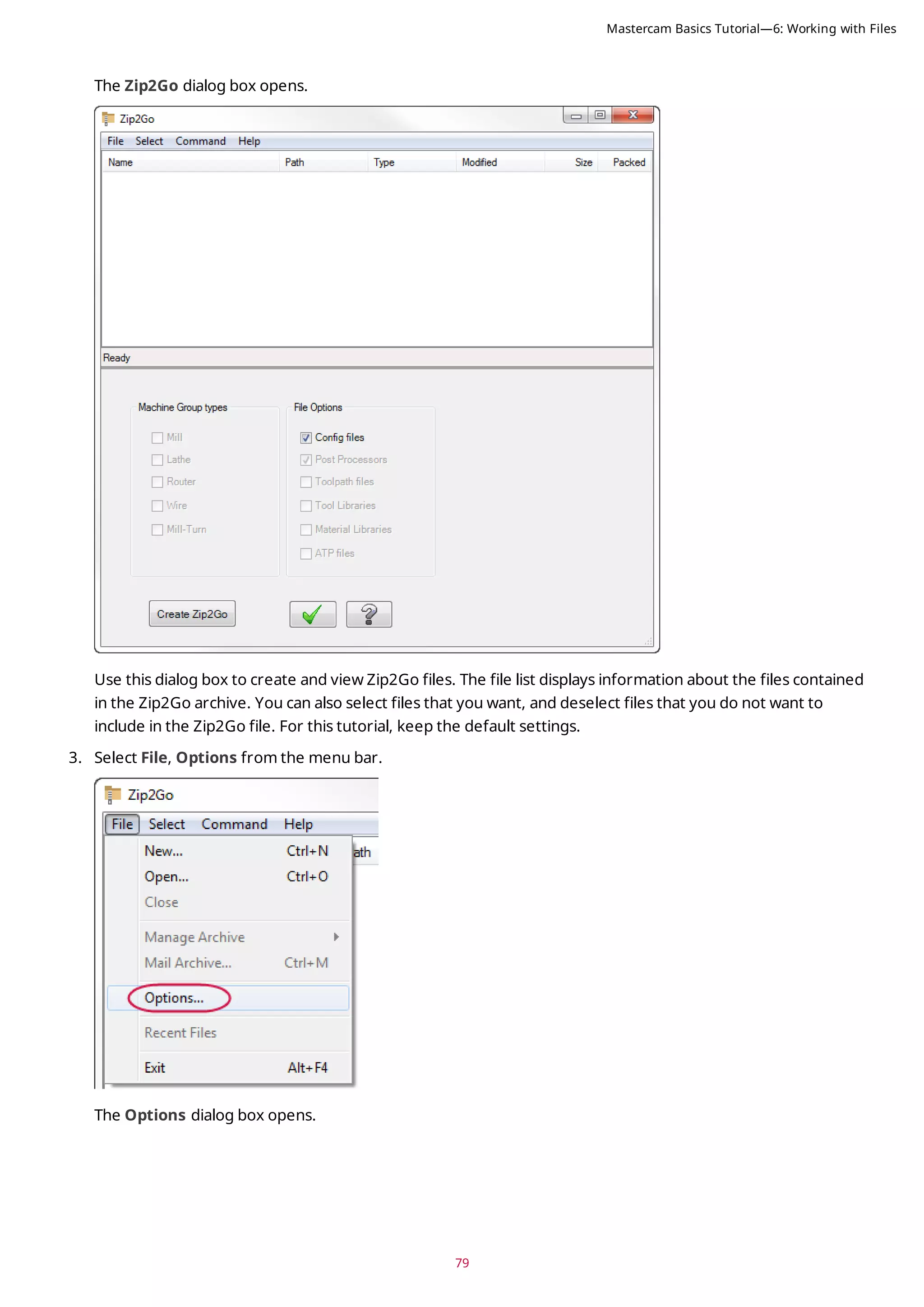
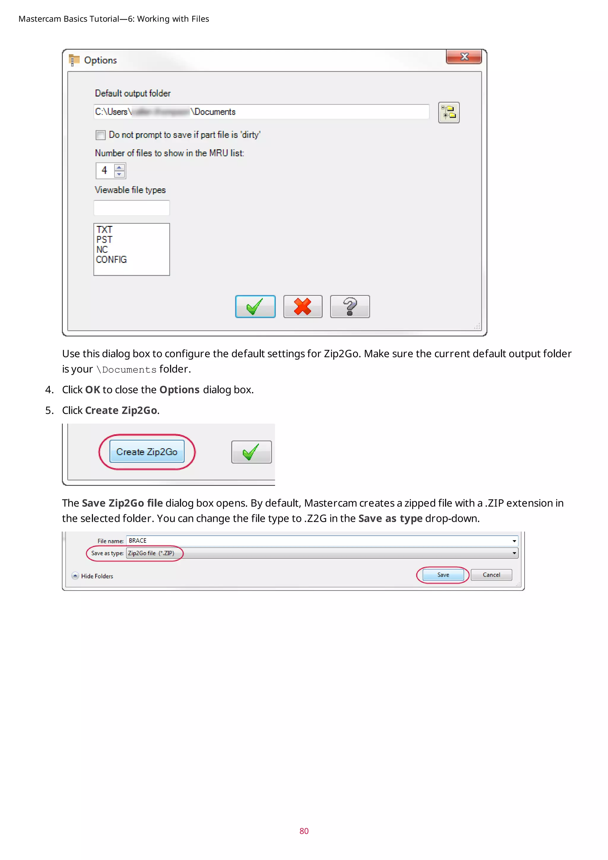
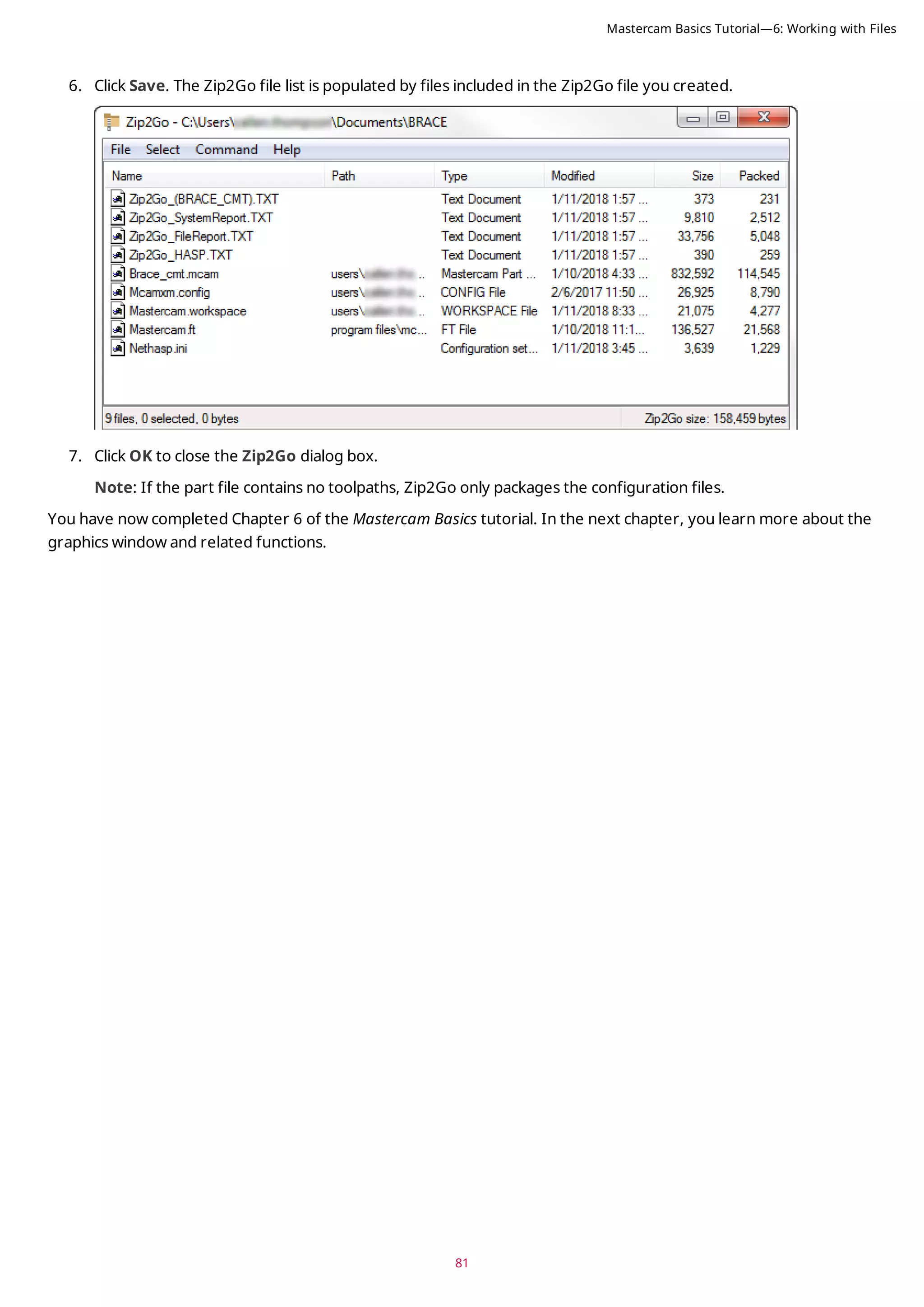
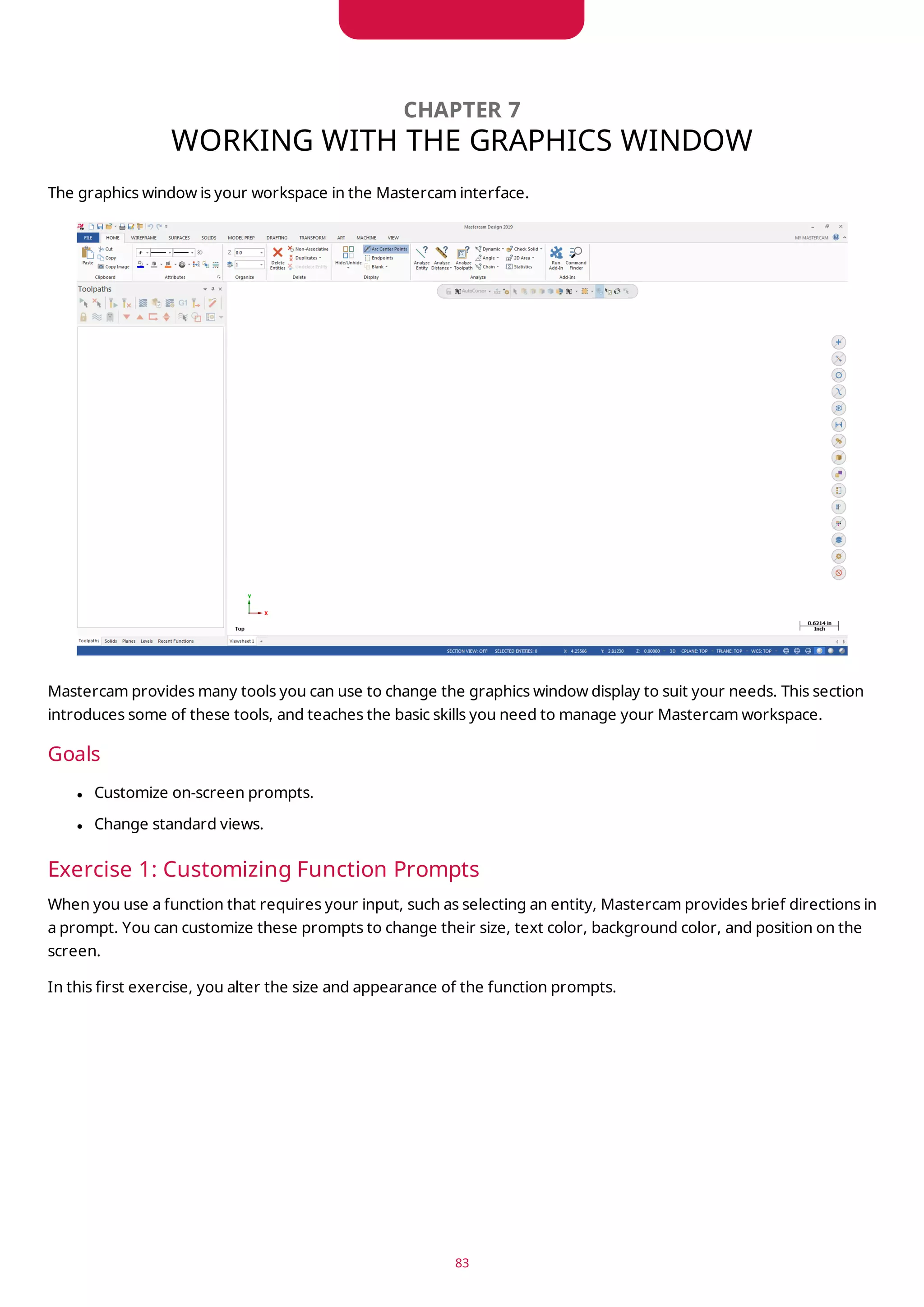
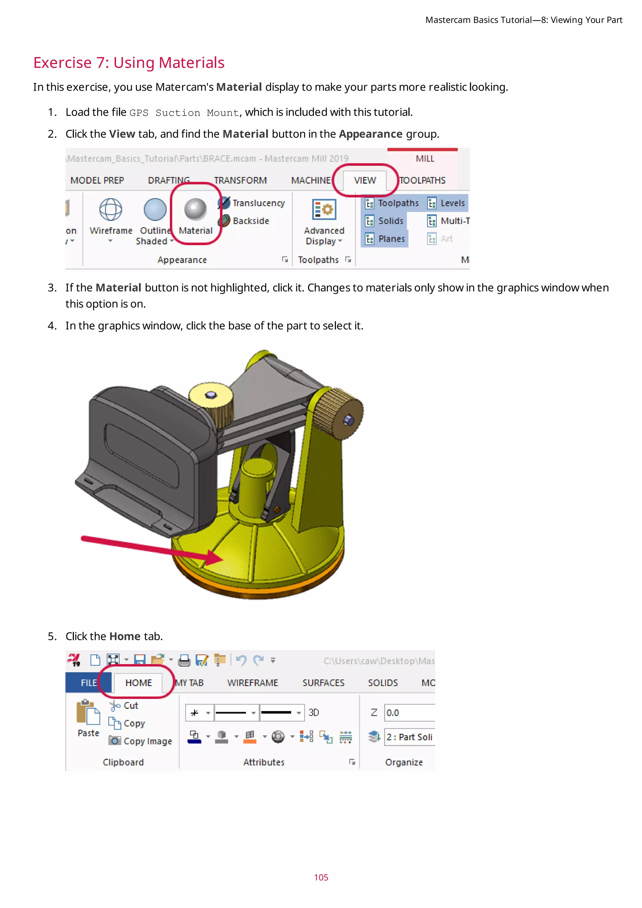
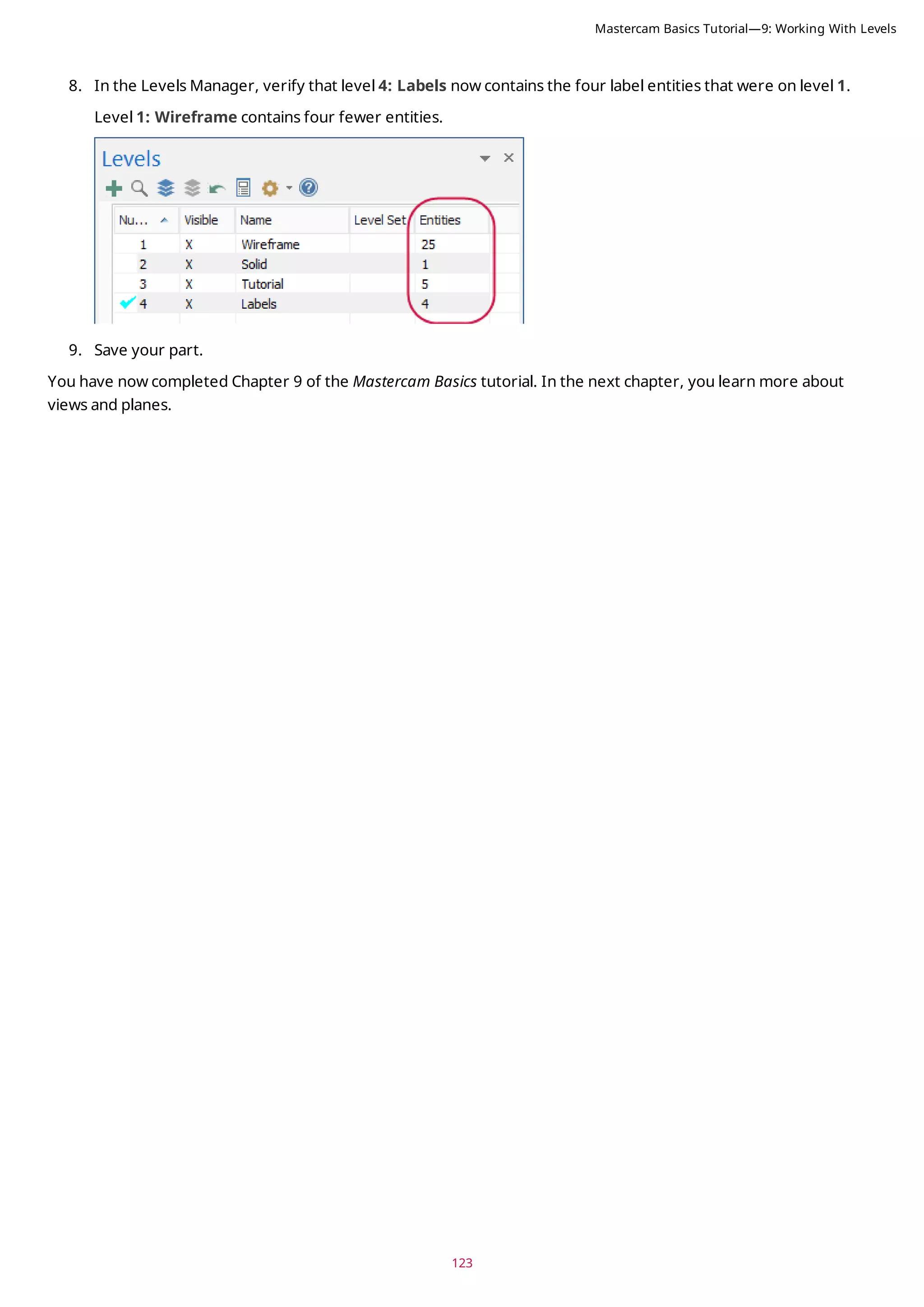
This document provides an overview of Mastercam's interface and includes exercises to familiarize users with key interface elements. It covers the Quick Access Toolbar, ribbon interface, selection bar, quick masks, status bar, and managers. Exercises guide users in customizing the Quick Access Toolbar, exploring the ribbon tabs, setting system attributes, and using common interface controls. The tutorial is intended to help users gain an understanding of Mastercam's interface and customize it for their workflow.


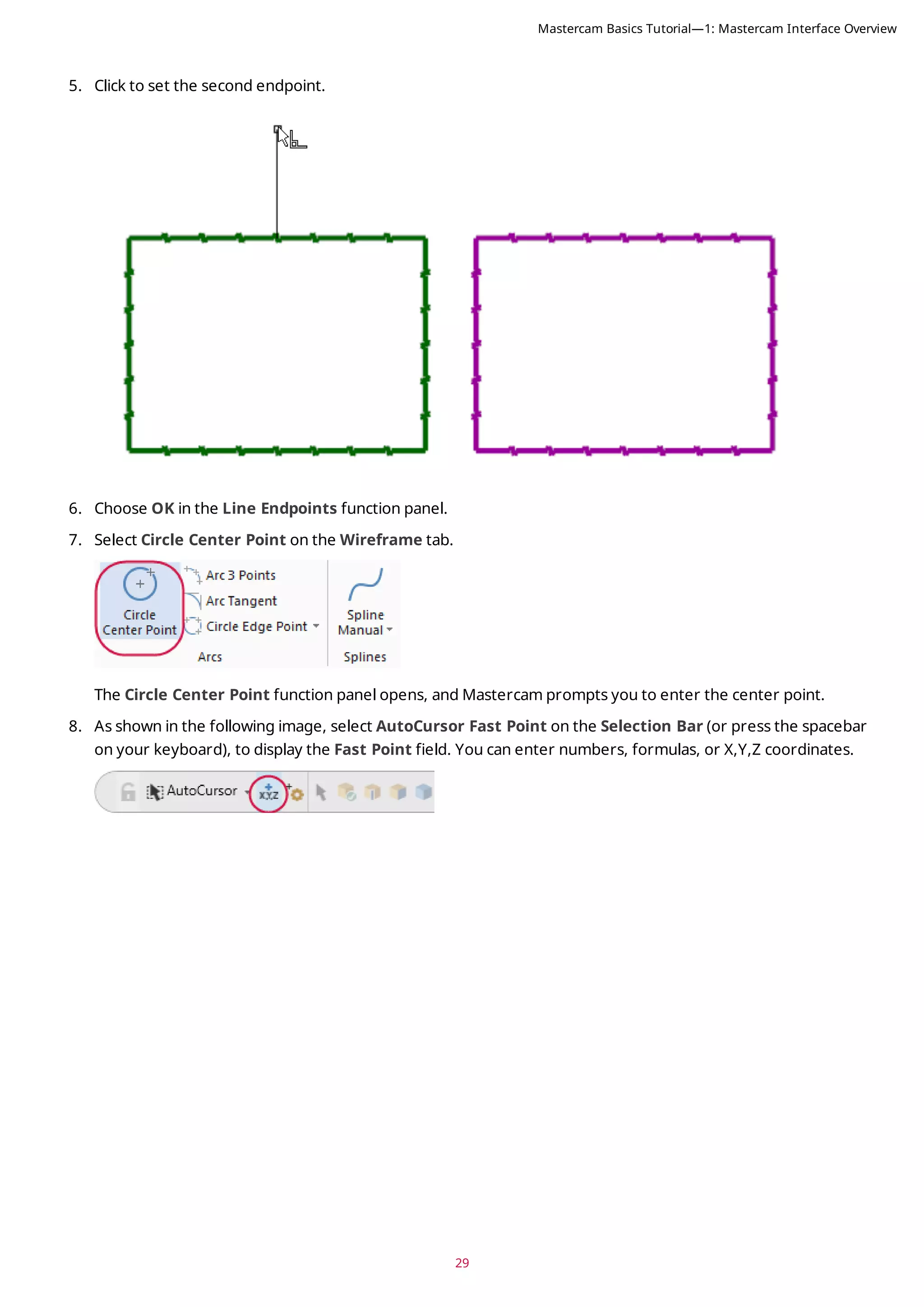
![9. Type 0,0,0 to enter the coordinate location of the circle’s center point, and then press [Enter].
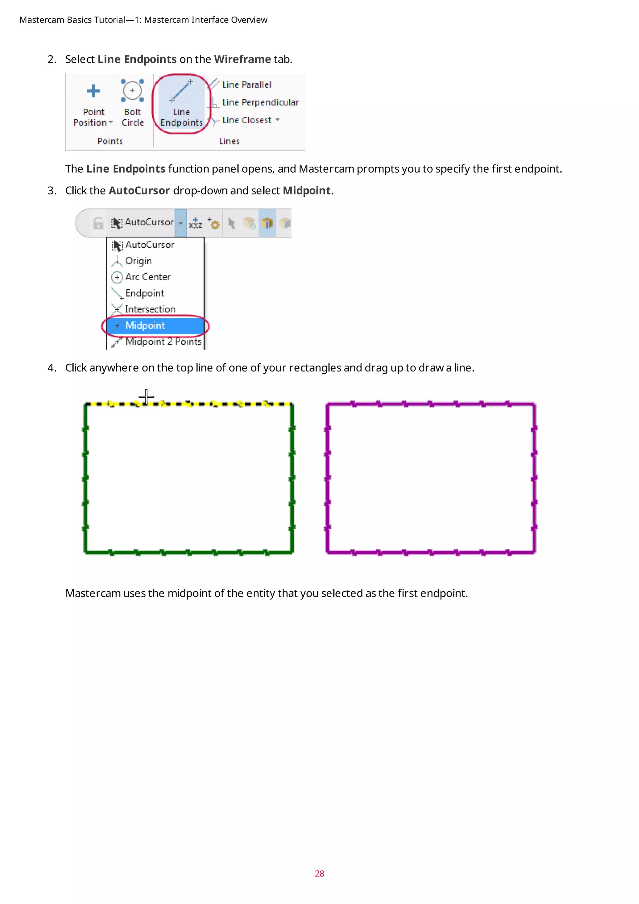
10. Drag and click to set the radius of the circle. The center point of the circle is at 0,0,0.
11. Choose OK in the Circle Center Point function panel.
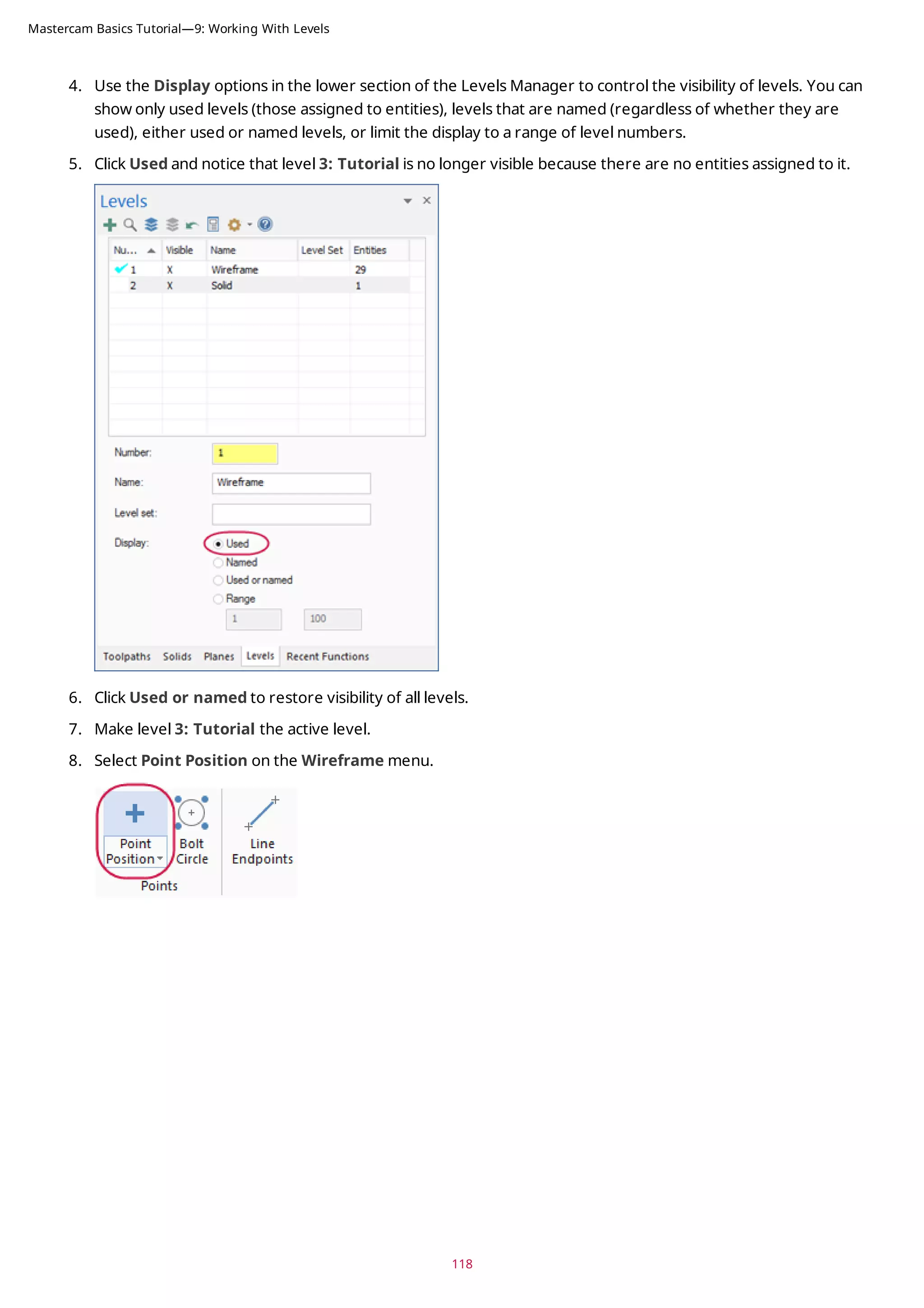
12. If the entities are outside of the graphics window, right-click and choose Fit.
13. Save your file.
30
Mastercam Basics Tutorial—1: Mastercam Interface Overview](https://image.slidesharecdn.com/mastercam-basics-tutorial-220225044543/75/Mastercam-basics-tutorial-30-2048.jpg)
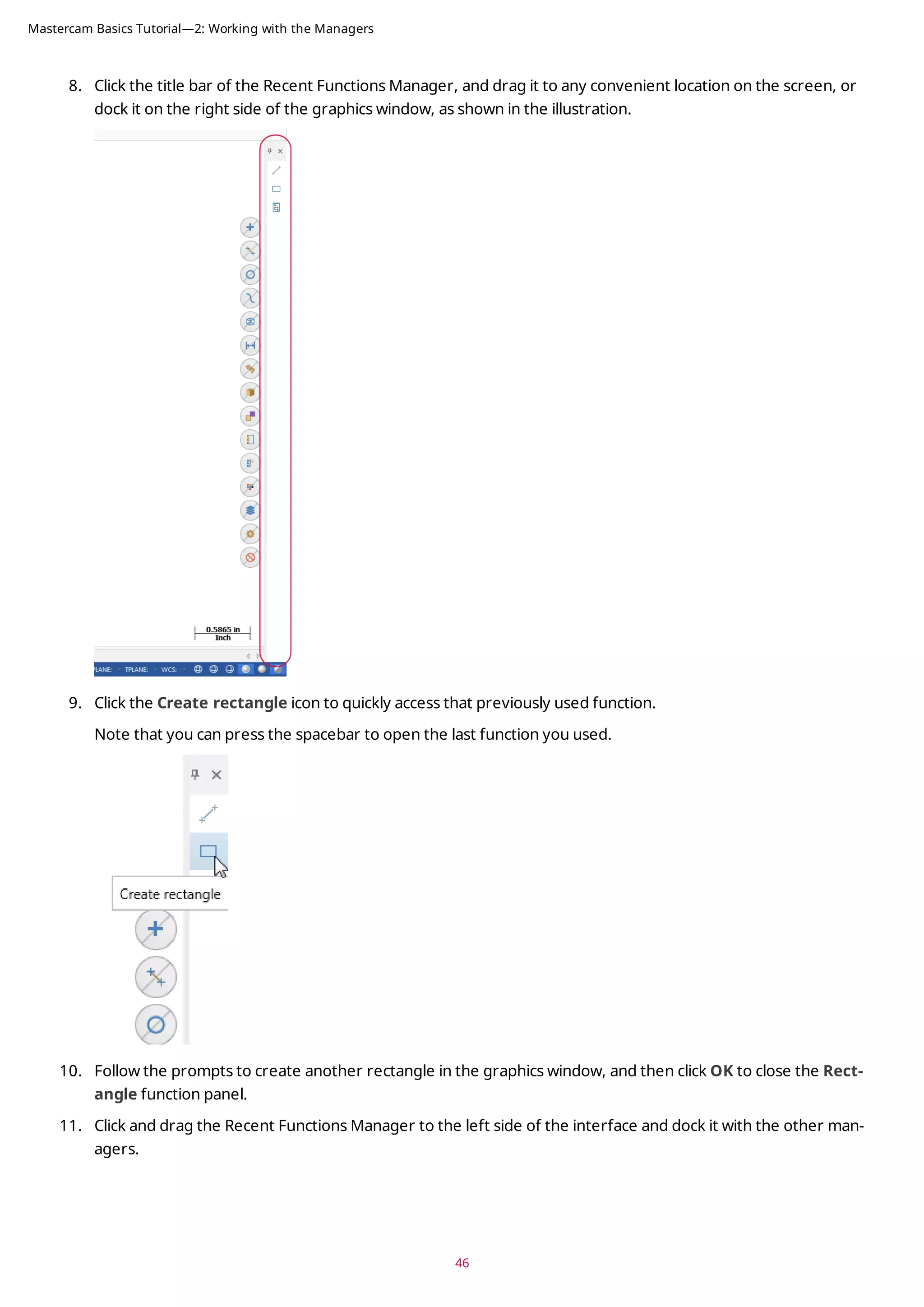
![41
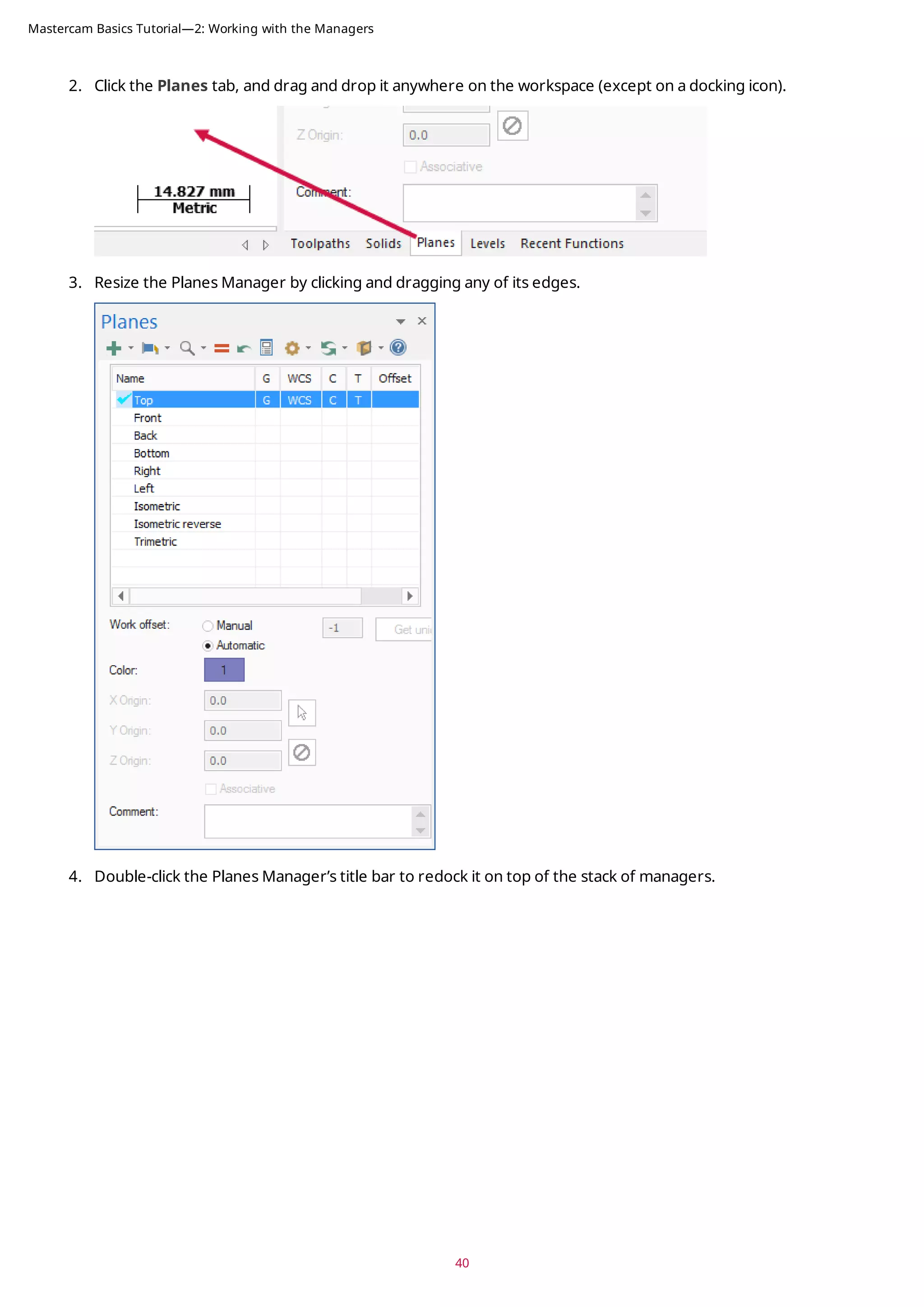
5. Click the title bar of the stack of managers, and drag it to the left side of the graphics window, where it was
docked at the beginning of this exercise.
Note: If you work with two monitors, position the managers onto the monitor that is not running Mastercam
to free the entire graphics window for drawing.
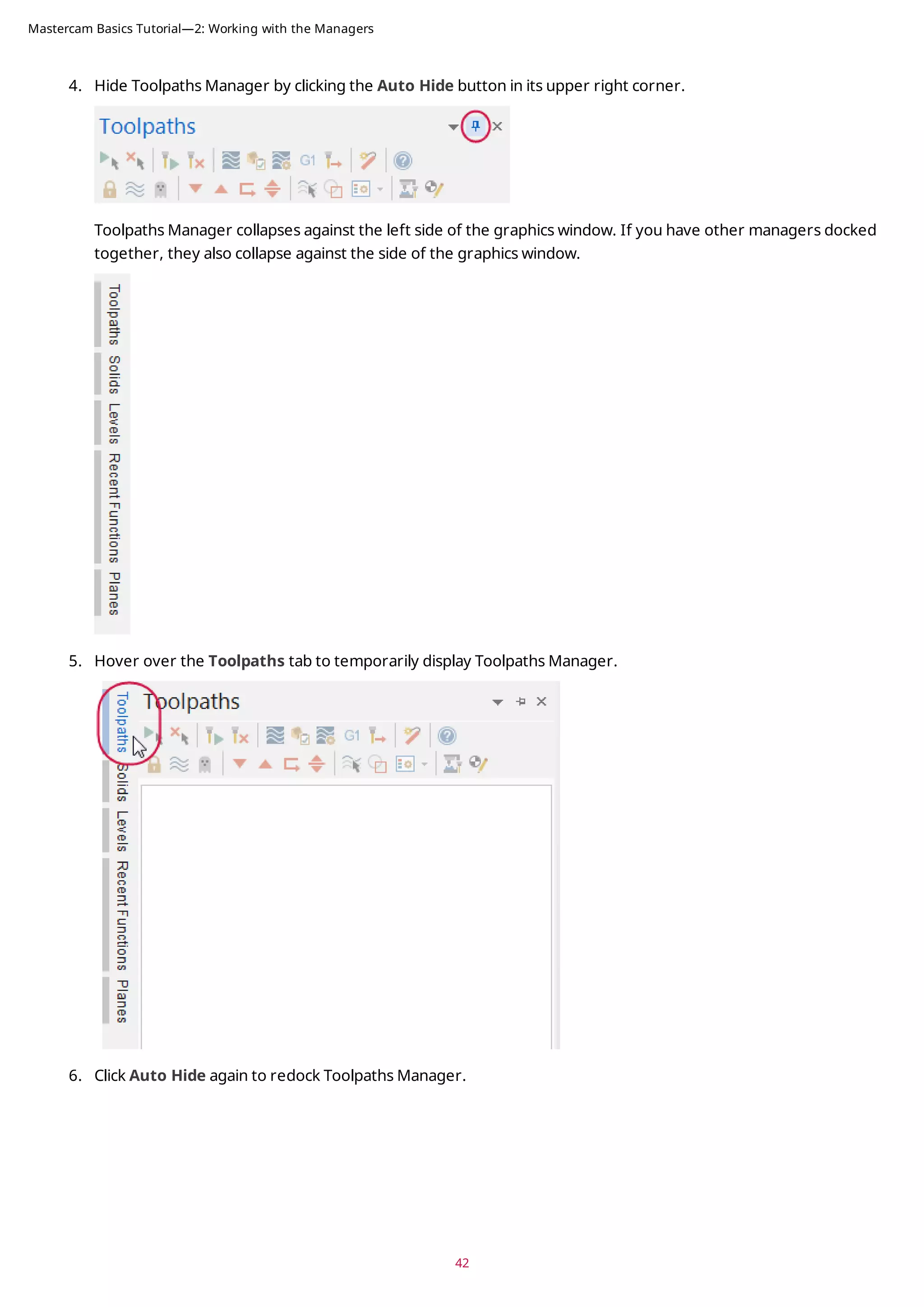
Exercise 2: Hiding and Displaying a Manager
In this exercise, you hide and display the Toolpaths Manager.
1. Click the Toolpaths tab to bring Toolpaths Manager to the front.
2. Hide Toolpaths Manager by clicking the Close button in its upper right corner.
3. Re-display Toolpaths Manager by choosing Toolpaths in the Managers group on the View tab.
Note: You can use the keyboard shortcut [Alt+O] to toggle the display of Toolpaths Manager.
Mastercam Basics Tutorial—2: Working with the Managers](https://image.slidesharecdn.com/mastercam-basics-tutorial-220225044543/75/Mastercam-basics-tutorial-41-2048.jpg)
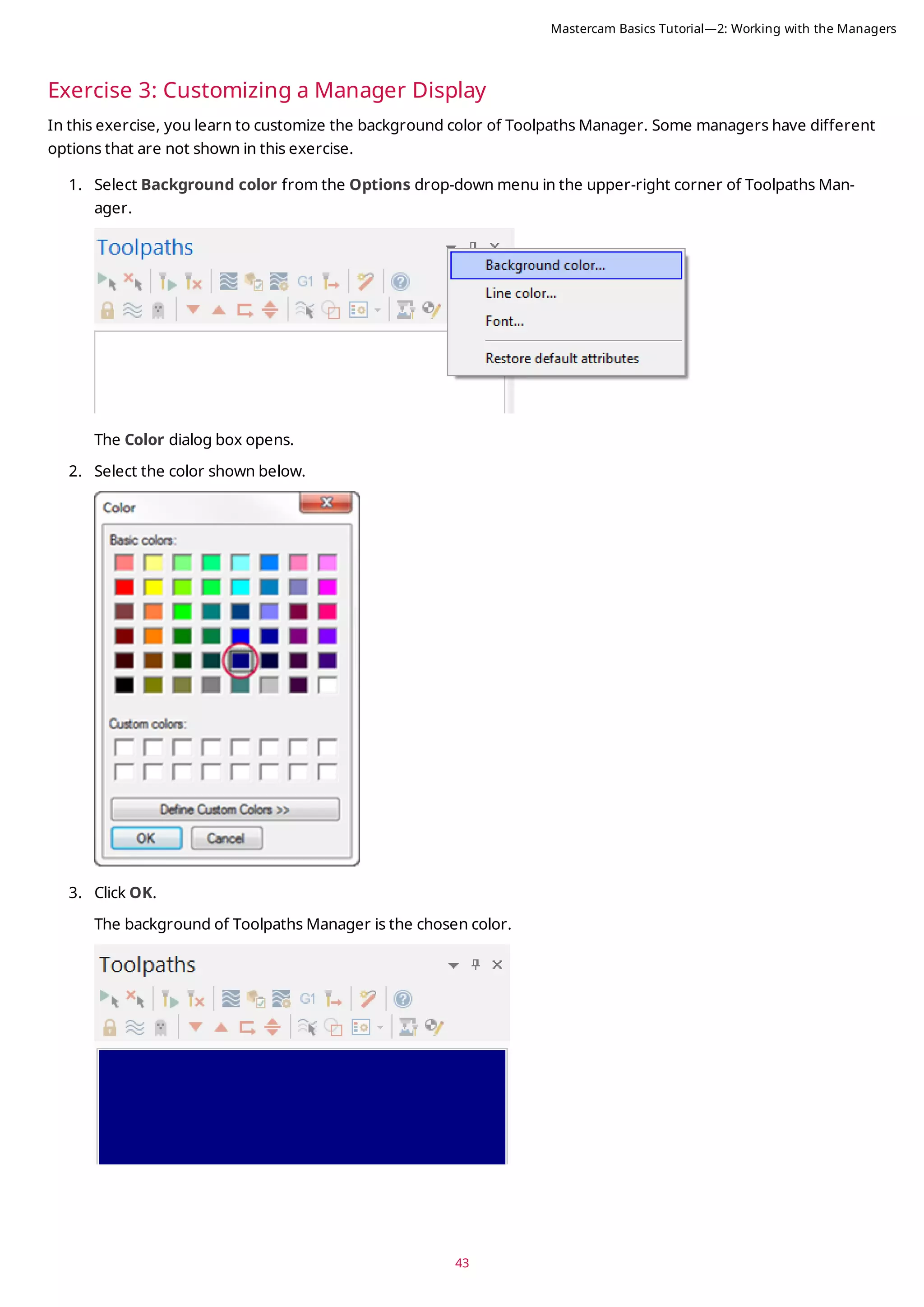


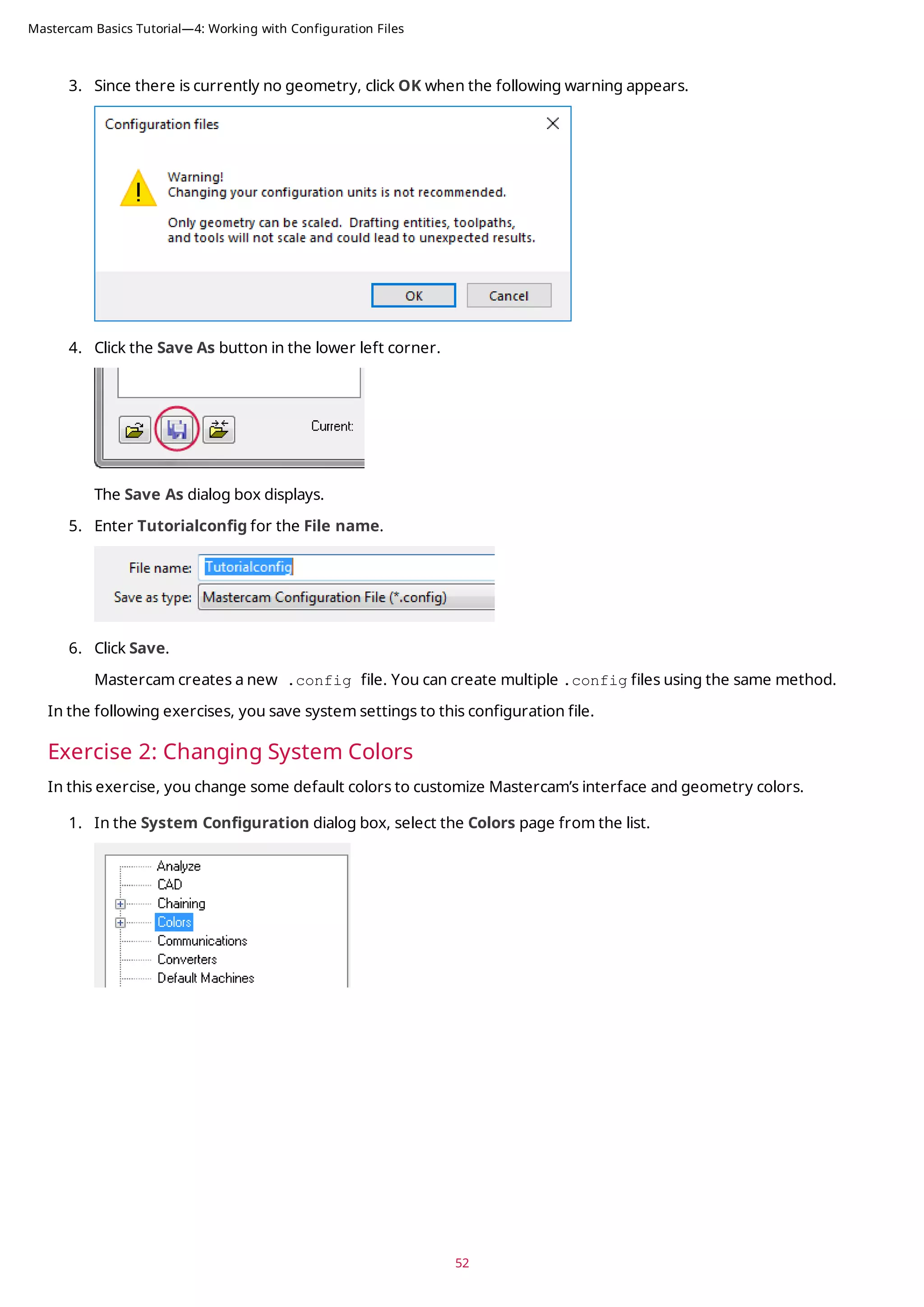
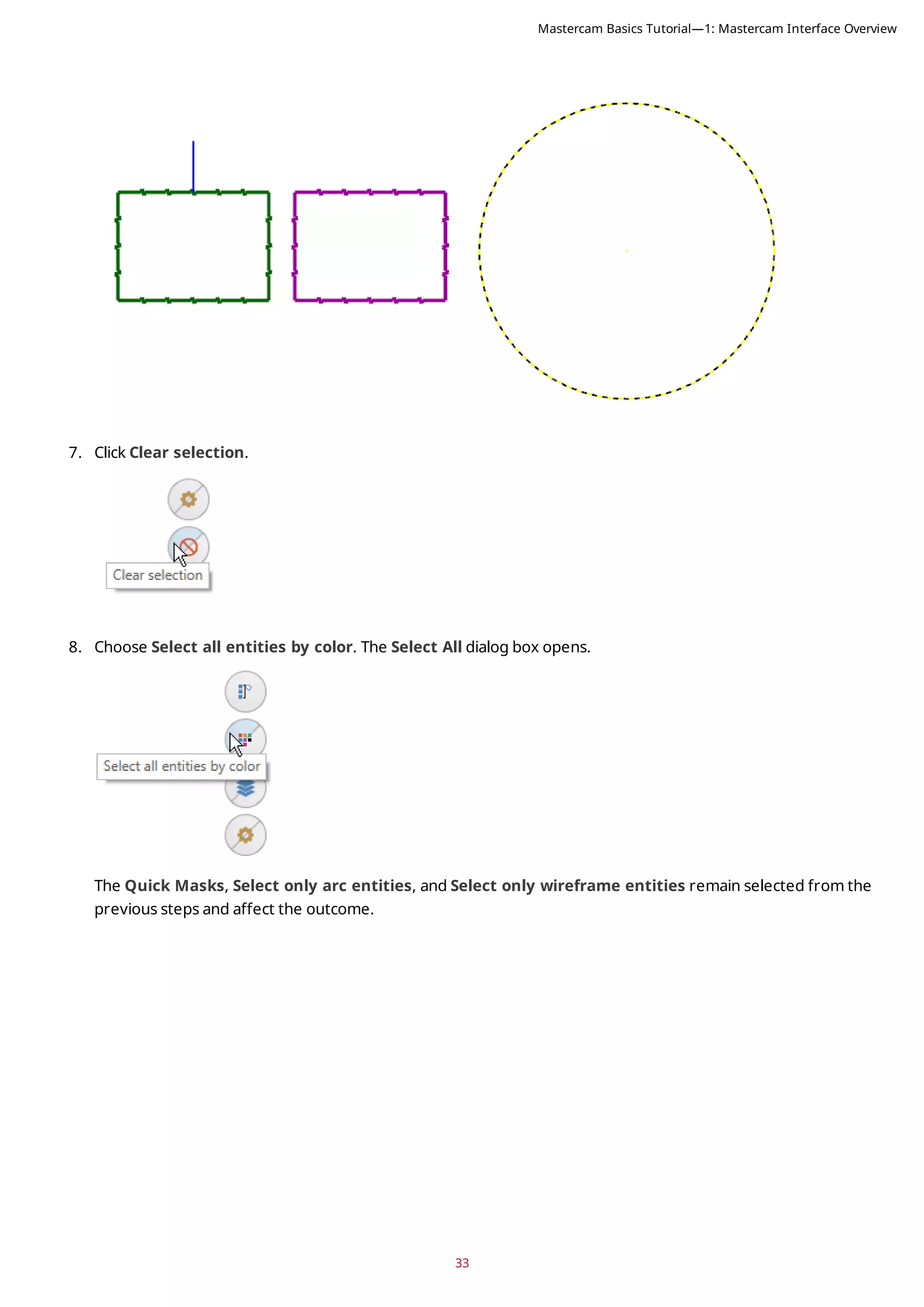
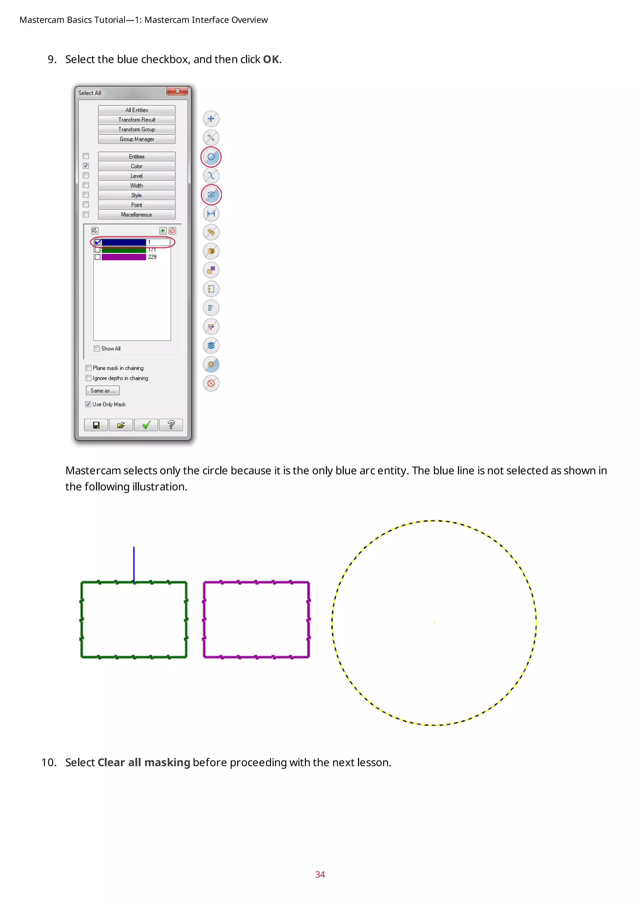
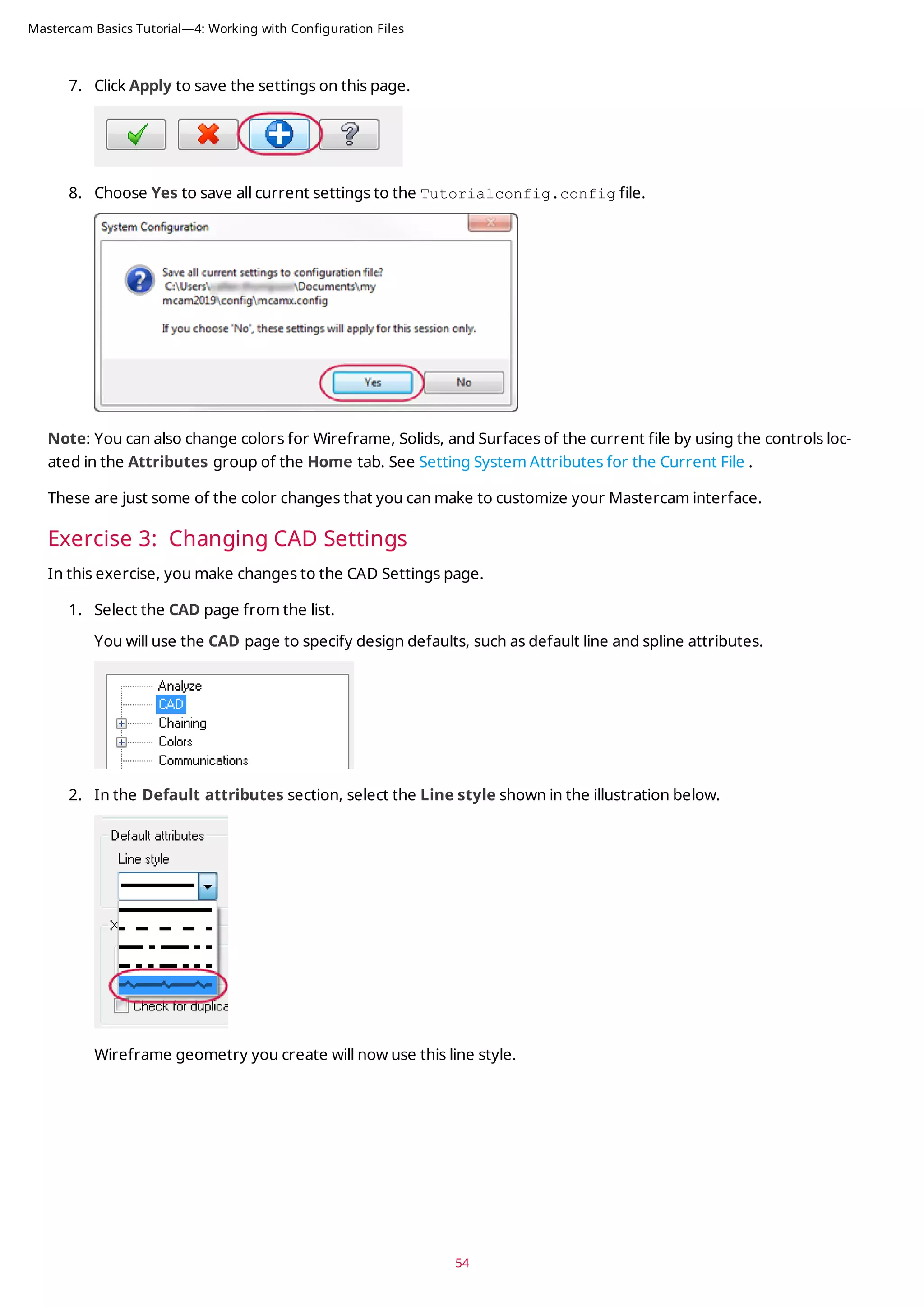
![53
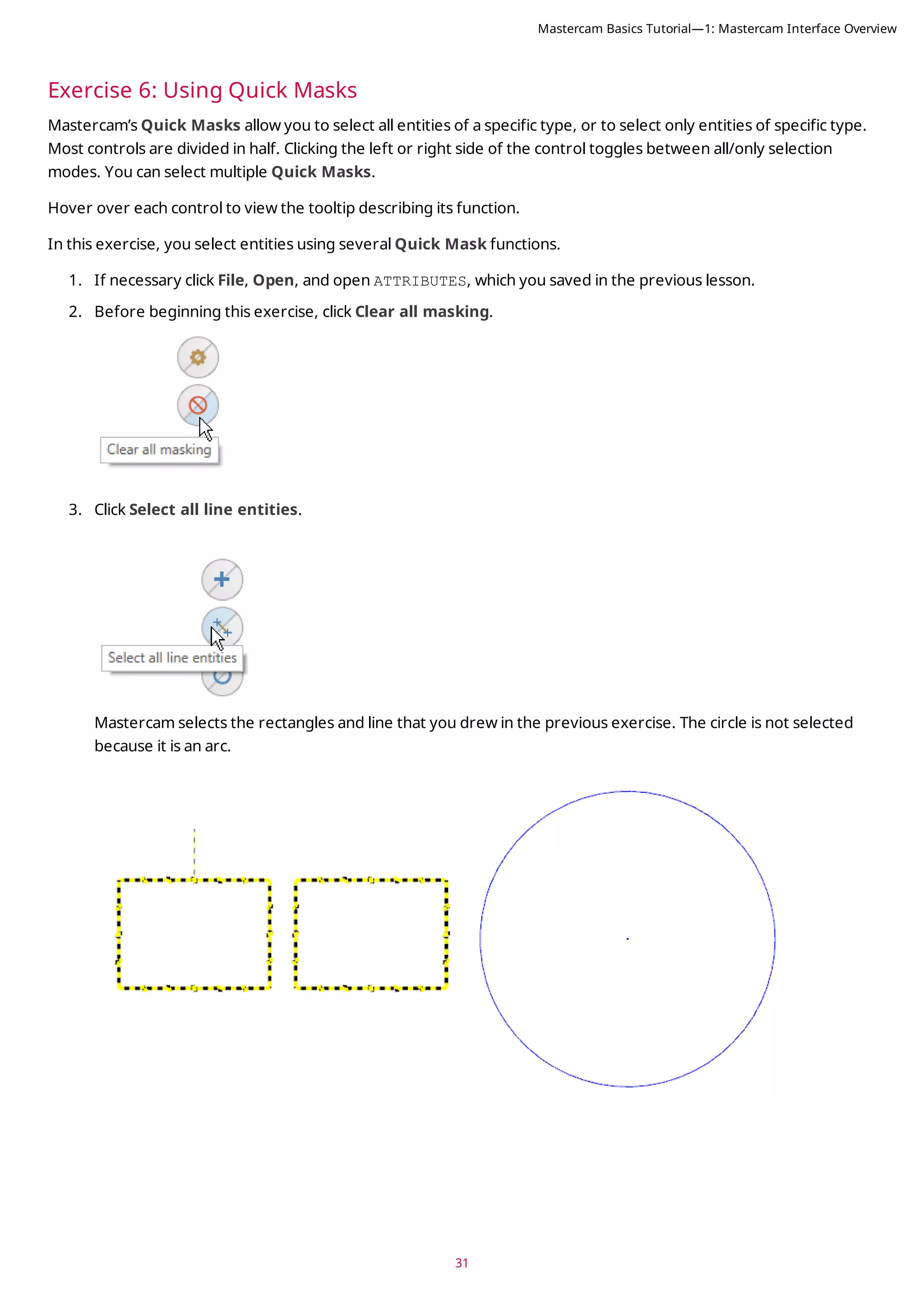
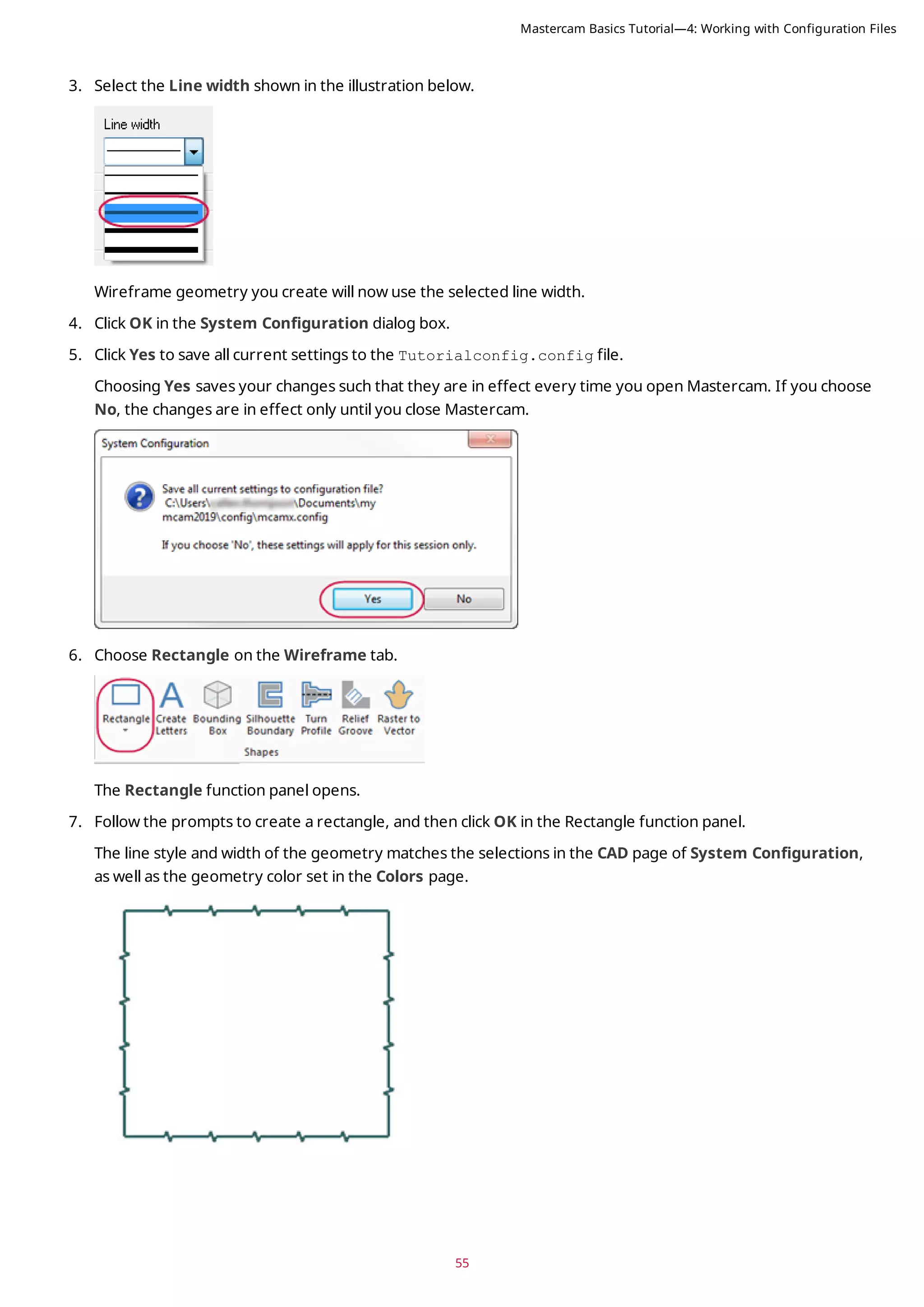
2. Select Wireframe geometry from the list.
You can see that Wireframe geometry is currently assigned to color 1.
3. Type 163 for the Color value, and press [Enter].
Wireframe geometry you create now uses this color.
4. Select Background (gradient start) from the list.
Color 111 is the current assignment.
5. Type 15 for the Color value, and press [Enter].
The start of the gradient background is now white.
6. Select None (Use Graphics background color) from the Gradient background direction drop-down.
This uses only the Background (gradient start), instead of creating a gradient background.
Mastercam Basics Tutorial—4: Working with Configuration Files](https://image.slidesharecdn.com/mastercam-basics-tutorial-220225044543/75/Mastercam-basics-tutorial-53-2048.jpg)
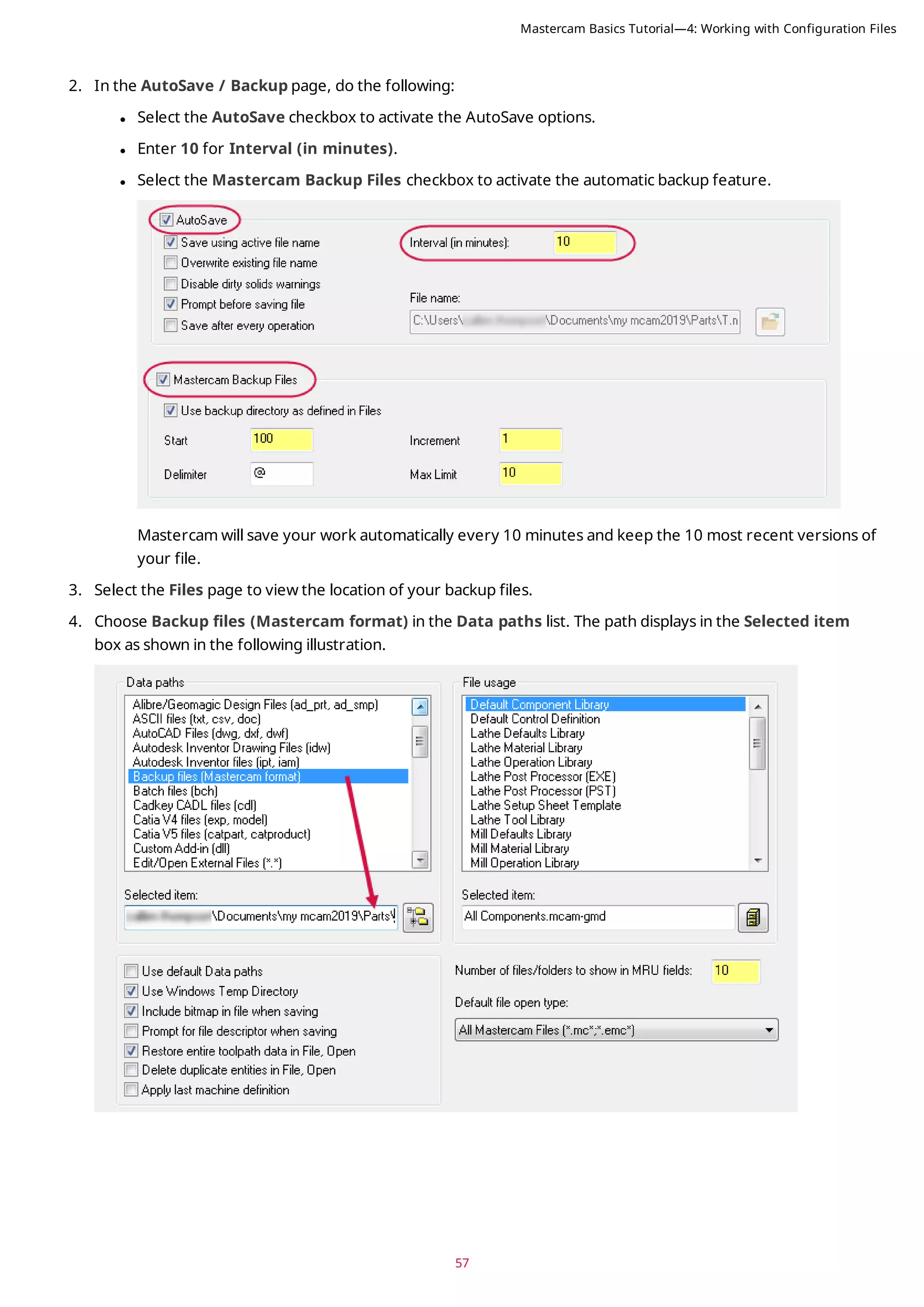
![Exercise 4: Changing the Size and Opacity of On-screen Controls
In this exercise, you set the size of the on-screen gnomons and text and change the opacity of the Selection Bar
and Quick Mask buttons.
1. Click File, Configuration to open the System Configuration dialog box.
2. Select the Screen page.
3. In the Graphics window overlays section, type 1.5 for Scale display gnomons and text and press [Enter].
The size of the elements is immediately changed in the graphics window.
4. The slider control for Selection controls opacity adjusts the opacity of the Selection Bar and Quick Masks.
The setting only affects the static display of the on-screen controls. The Selection Bar and Quick Mask con-
trols become opaque when you hover over them. Move the slider to the left to increase transparency and to
the right to increase opacity. Watch as the opacity changes with the slider movement, and choose a opacity
setting you like.
5. Click Apply to save the settings on this page.
6. Select Yes to save the settings to the configuration file.
Exercise 5: Setting up AutoSave and Backup
When you are working on a part, Mastercam can save your work automatically, at intervals that you specify. Master-
cam can also save versions of your files as backups.
In this exercise, you set up these functions.
1. Expand the Files category, and select the AutoSave / Backup page.
56
Mastercam Basics Tutorial—4: Working with Configuration Files](https://image.slidesharecdn.com/mastercam-basics-tutorial-220225044543/75/Mastercam-basics-tutorial-56-2048.jpg)
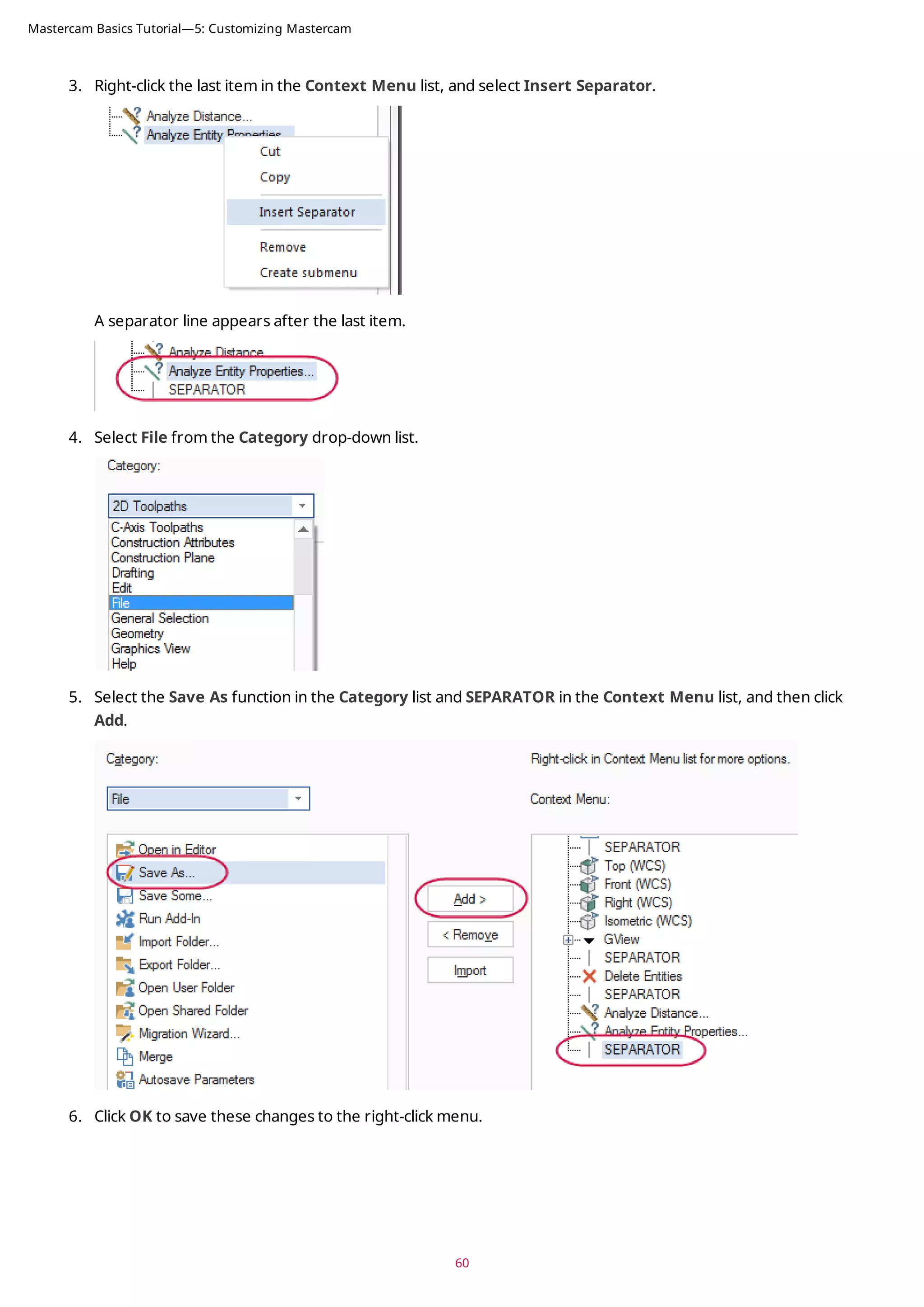
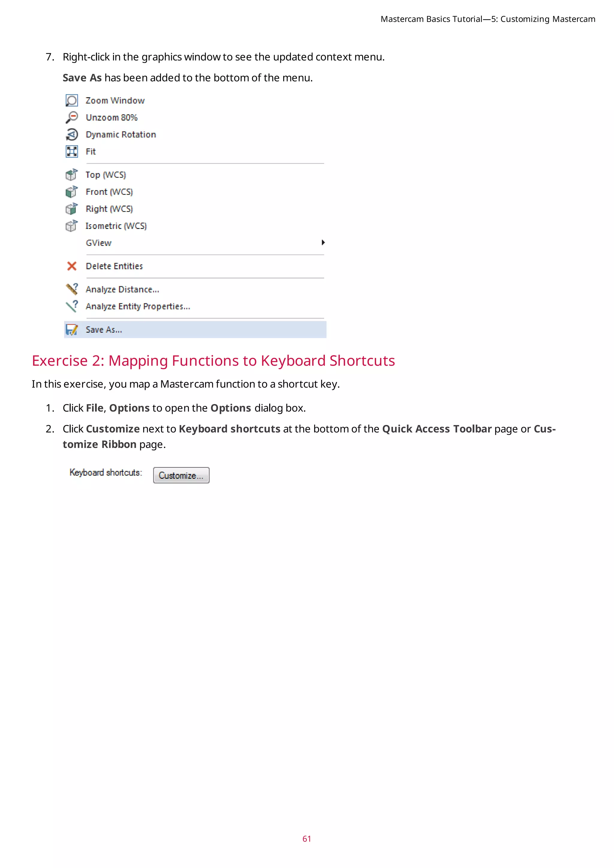
![The Customize Keyboard dialog box opens.
3. Select Home from the Categories list.
The Commands list populates with functions from the Home tab.
4. Select Statistics from the Commands list.
Notice that the Current Keys list is blank. This is because there are no shortcut keys assigned to this function.
5. Click in Press new shortcut key, and press [Ctrl+Shift+H] to create a new shortcut key.
62
Mastercam Basics Tutorial—5: Customizing Mastercam](https://image.slidesharecdn.com/mastercam-basics-tutorial-220225044543/75/Mastercam-basics-tutorial-62-2048.jpg)
![63
6. Click Assign to map this shortcut key to the Statistics function.
7. Click Close to exit the Customize Keyboard dialog box, and then OK to close the Options dialog box.
8. In the graphics window, press [Ctrl+Shift+H] to access the Statistics function.
The Statistics dialog box displays a summary of the entities in the current file, including total number of vis-
ible entities by type, and the number of operations and tools.
In this example, Statistics reports four lines because of the rectangle created in the previous lesson.
9. Click OK to close Statistics.
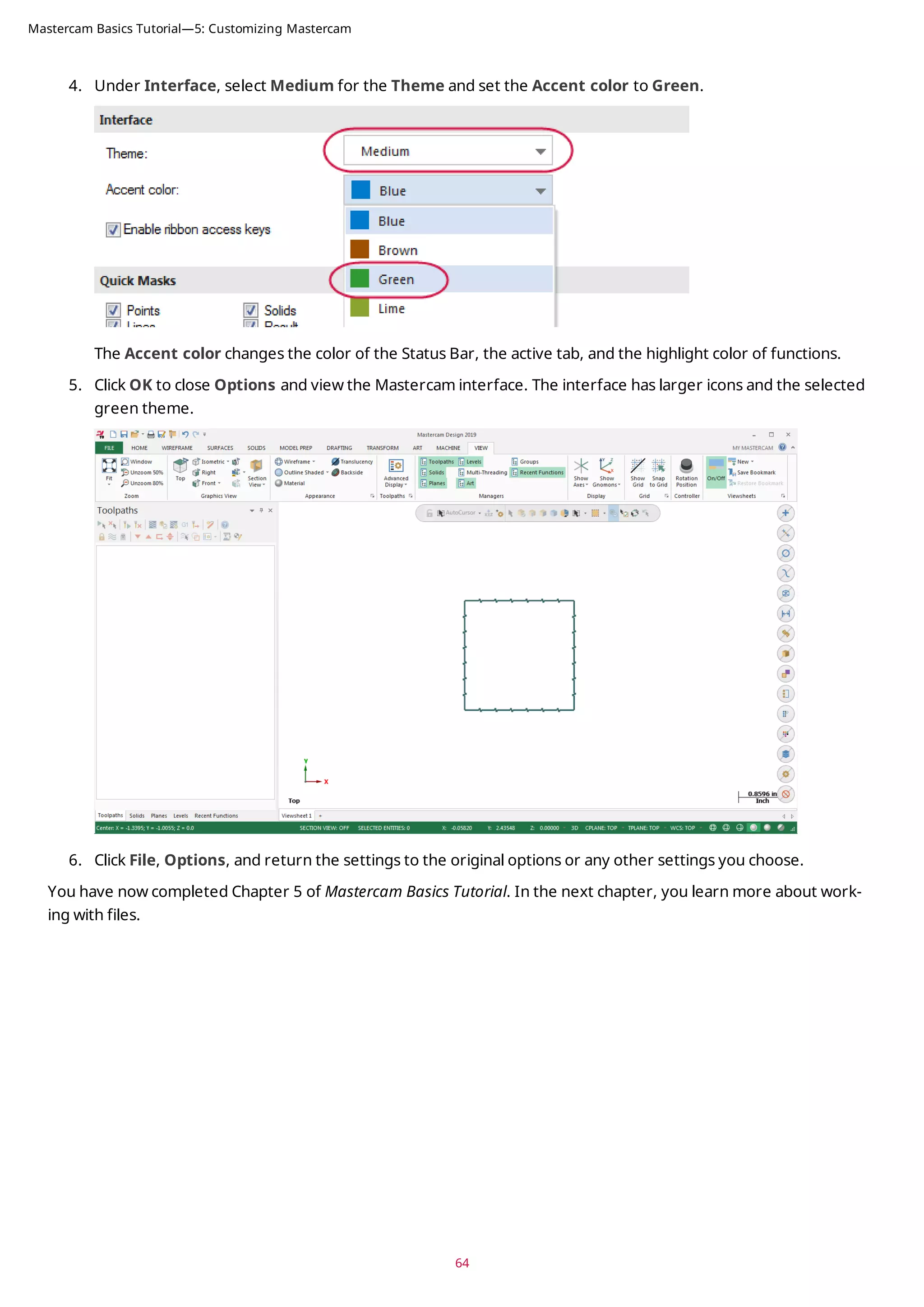
Exercise 3: Setting Mastercam Display Options
In this exercise, you set some of Mastercam’s display options.
1. Select File, Options to open the Options dialog box.
2. Select the Options page.
3. Under the Manager panels section, select Large icons.
Mastercam Basics Tutorial—5: Customizing Mastercam](https://image.slidesharecdn.com/mastercam-basics-tutorial-220225044543/75/Mastercam-basics-tutorial-63-2048.jpg)
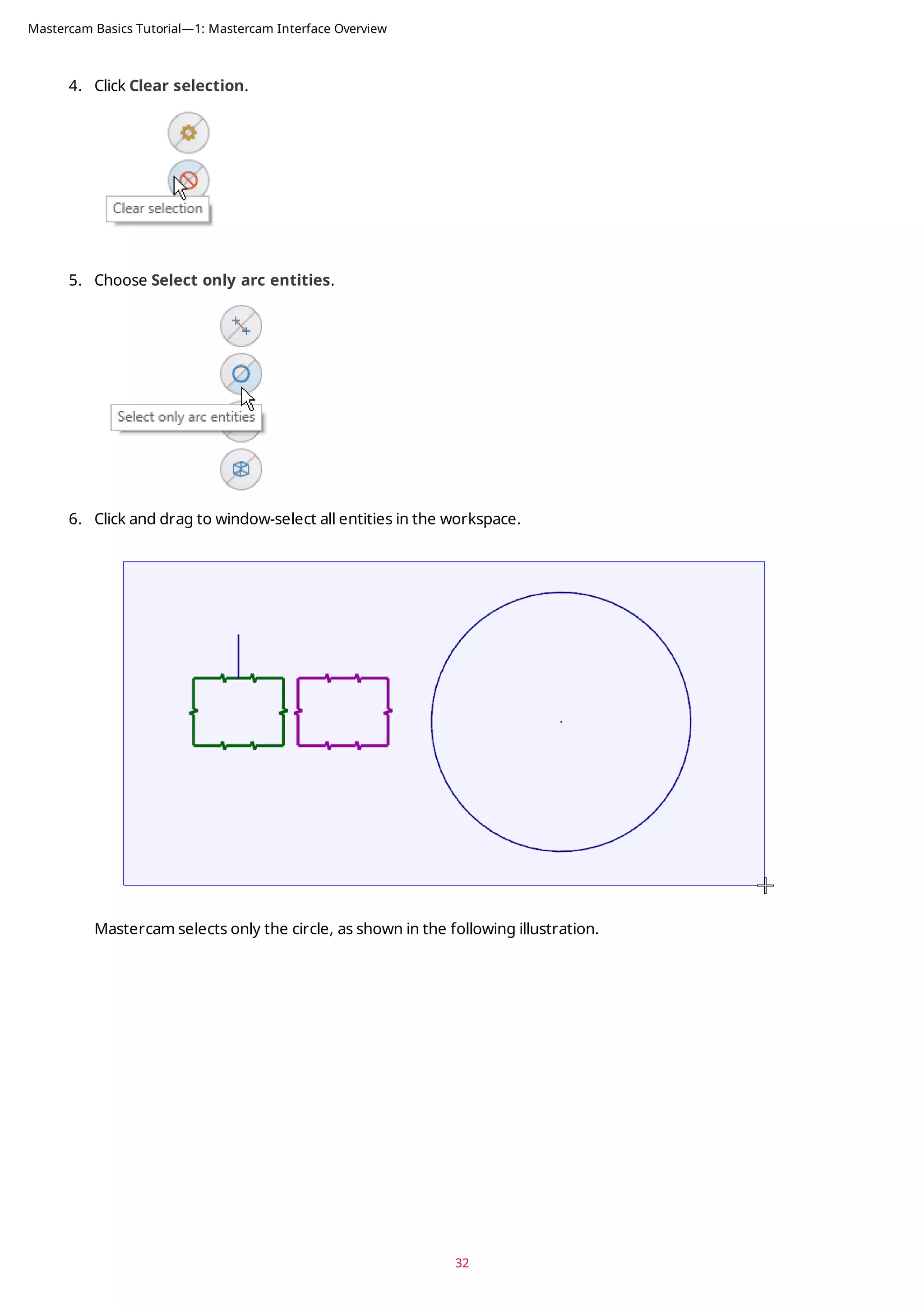
![4. Select the five arcs shown in the picture below. The arcs change color when they are selected.
5. Press [Enter] to accept the selection. The Save As dialog box opens.
6. Type 2D_CHAMFER_ARCS for the File name.
7. Click Save or press [Enter] to save the file. Mastercam saves only the selected arcs.
8. Open 2D_CHAMFER_ARCS, and notice that it contains only the arcs that you selected.
72
Mastercam Basics Tutorial—6: Working with Files](https://image.slidesharecdn.com/mastercam-basics-tutorial-220225044543/75/Mastercam-basics-tutorial-72-2048.jpg)

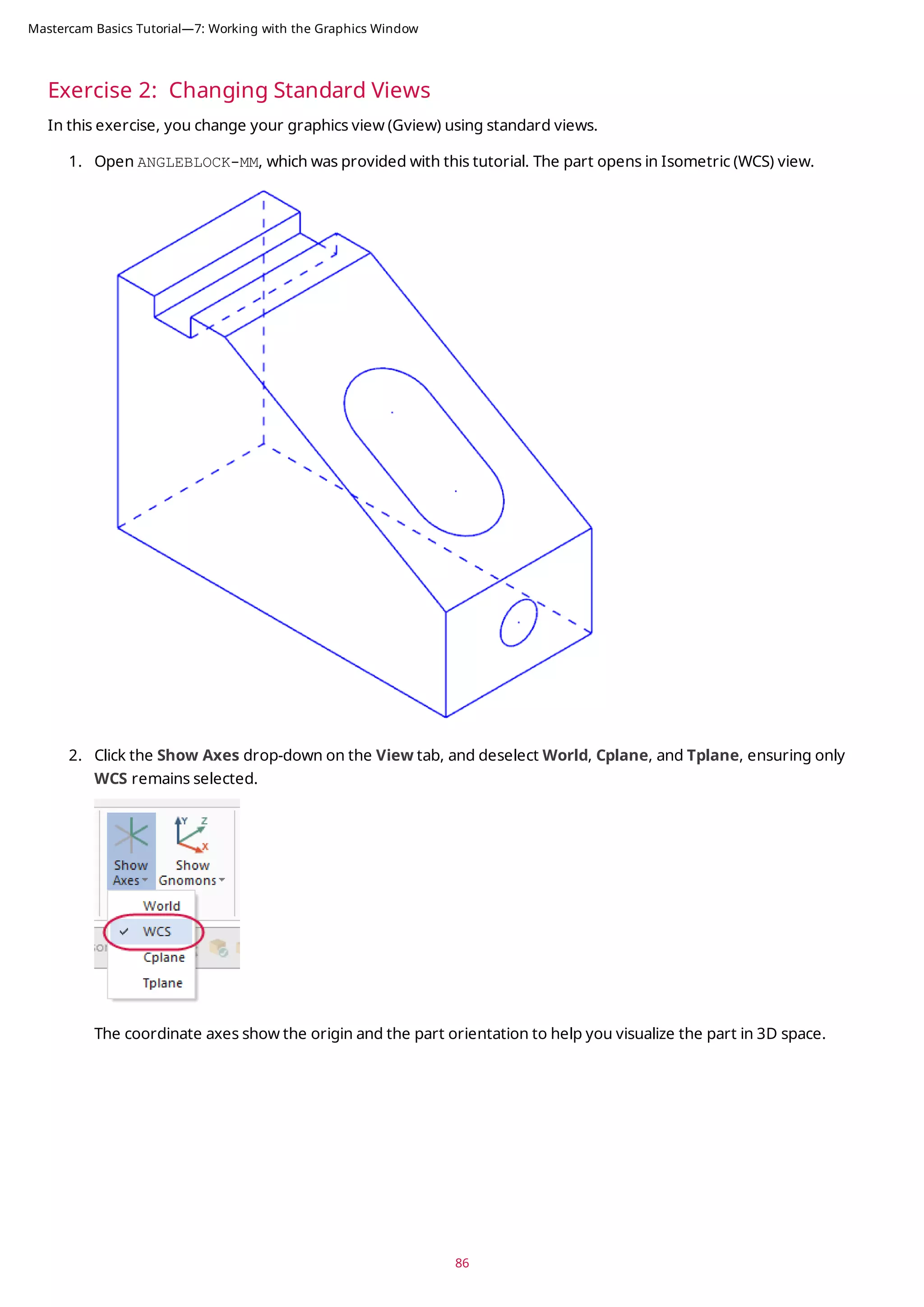
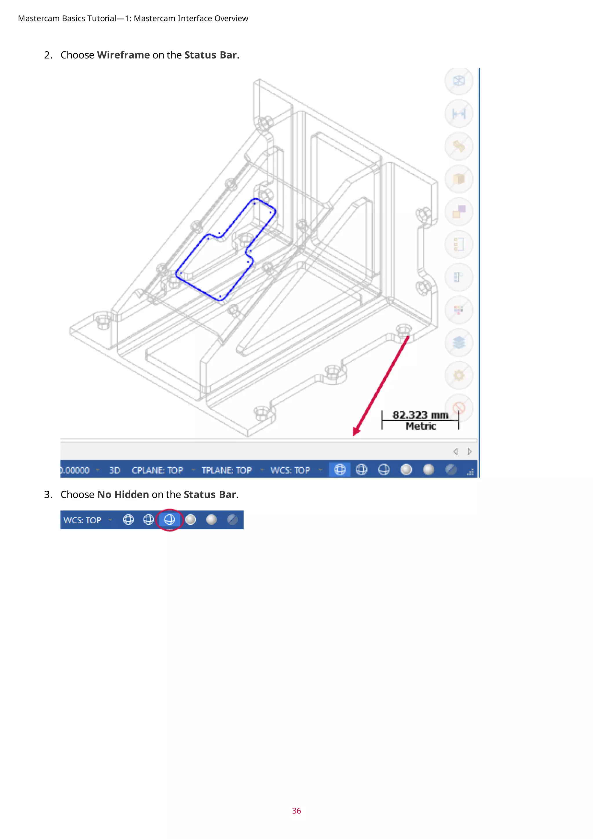
![87
3. Click Show Axes on the View tab or press [F9] to toggle the display of the WCS axes.
4. Click the Show Gnomons drop-down on the View tab, and deselect Cplane and Tplane, ensuring only WCS is
selected.
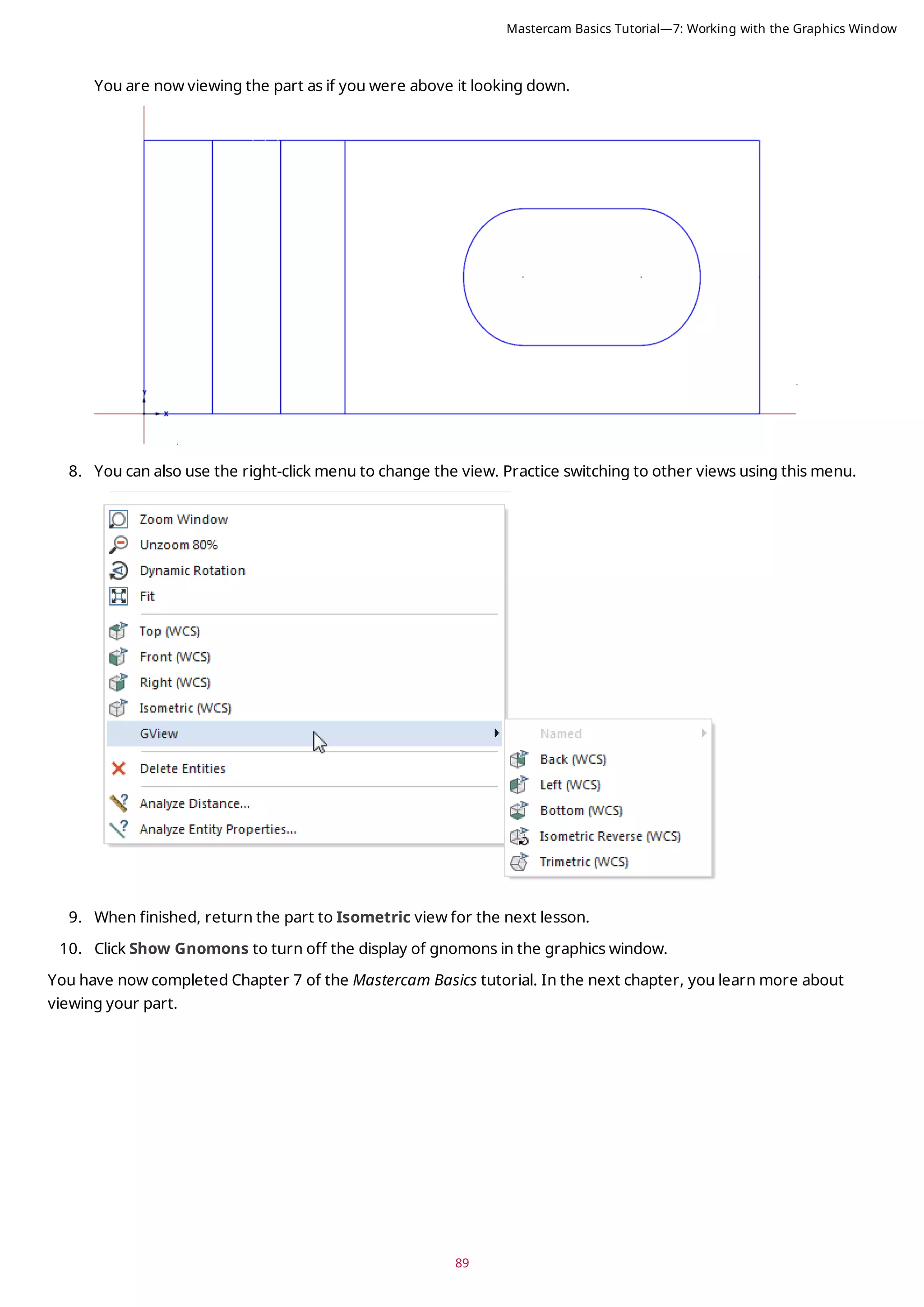
Mastercam Basics Tutorial—7: Working with the Graphics Window](https://image.slidesharecdn.com/mastercam-basics-tutorial-220225044543/75/Mastercam-basics-tutorial-87-2048.jpg)
![5. Click Show Gnomons or press [Alt+F9] to toggle the display of the on-screen gnomon.
6. On the View tab, click Top in the Graphics View group.
7. Click Unzoom 80% on the View tab to reduce the size of the part on the screen.
88
Mastercam Basics Tutorial—7: Working with the Graphics Window](https://image.slidesharecdn.com/mastercam-basics-tutorial-220225044543/75/Mastercam-basics-tutorial-88-2048.jpg)

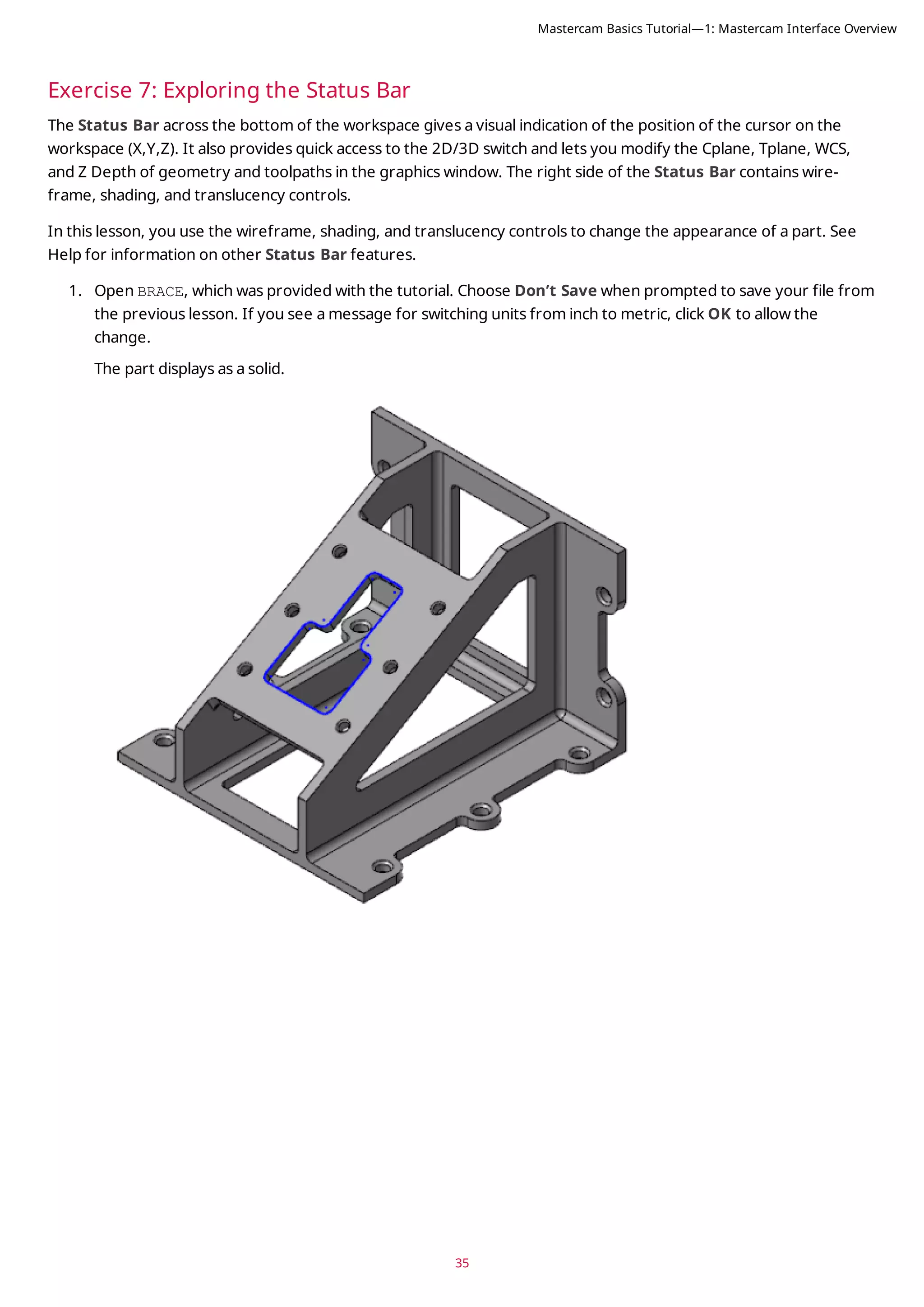
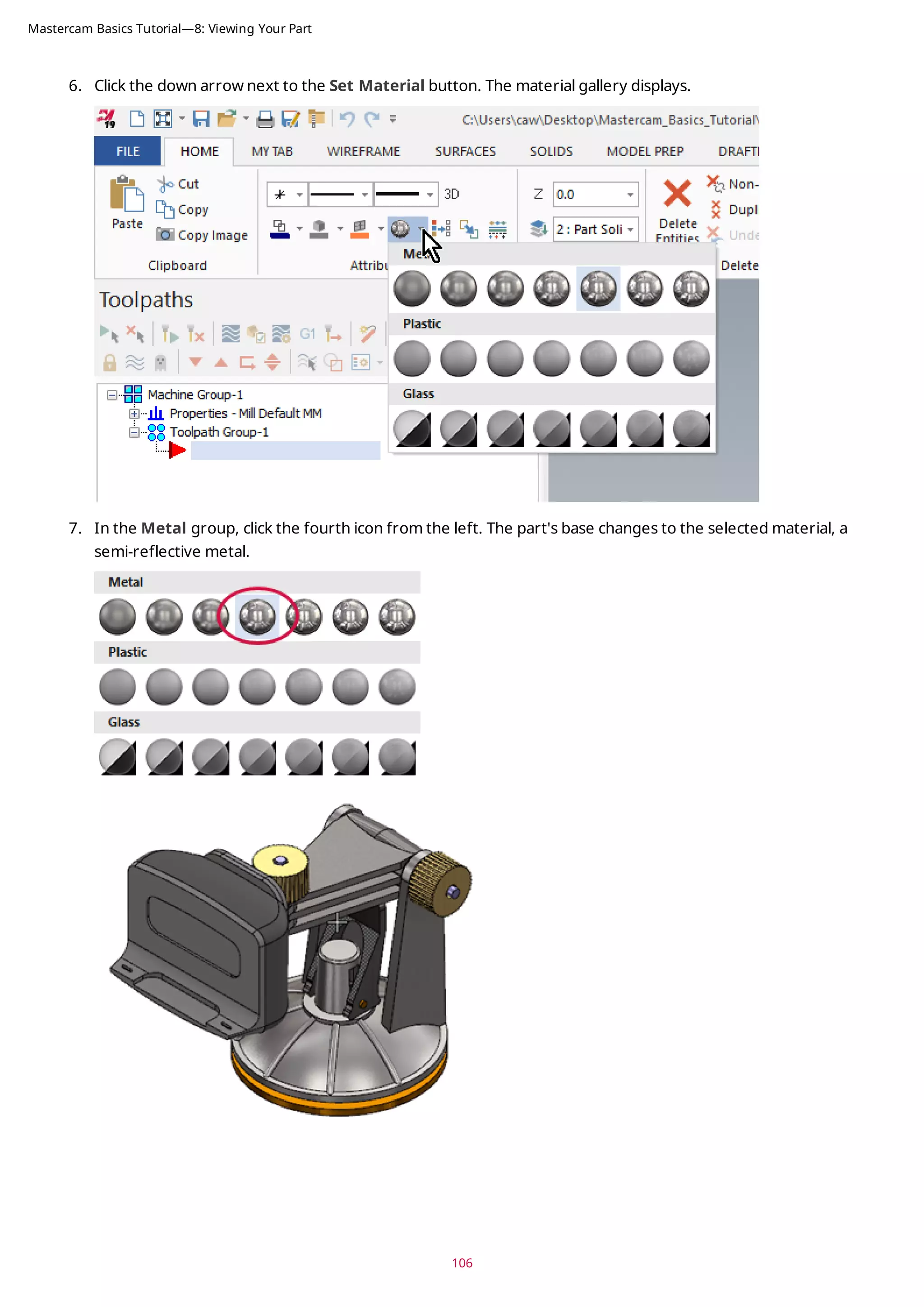
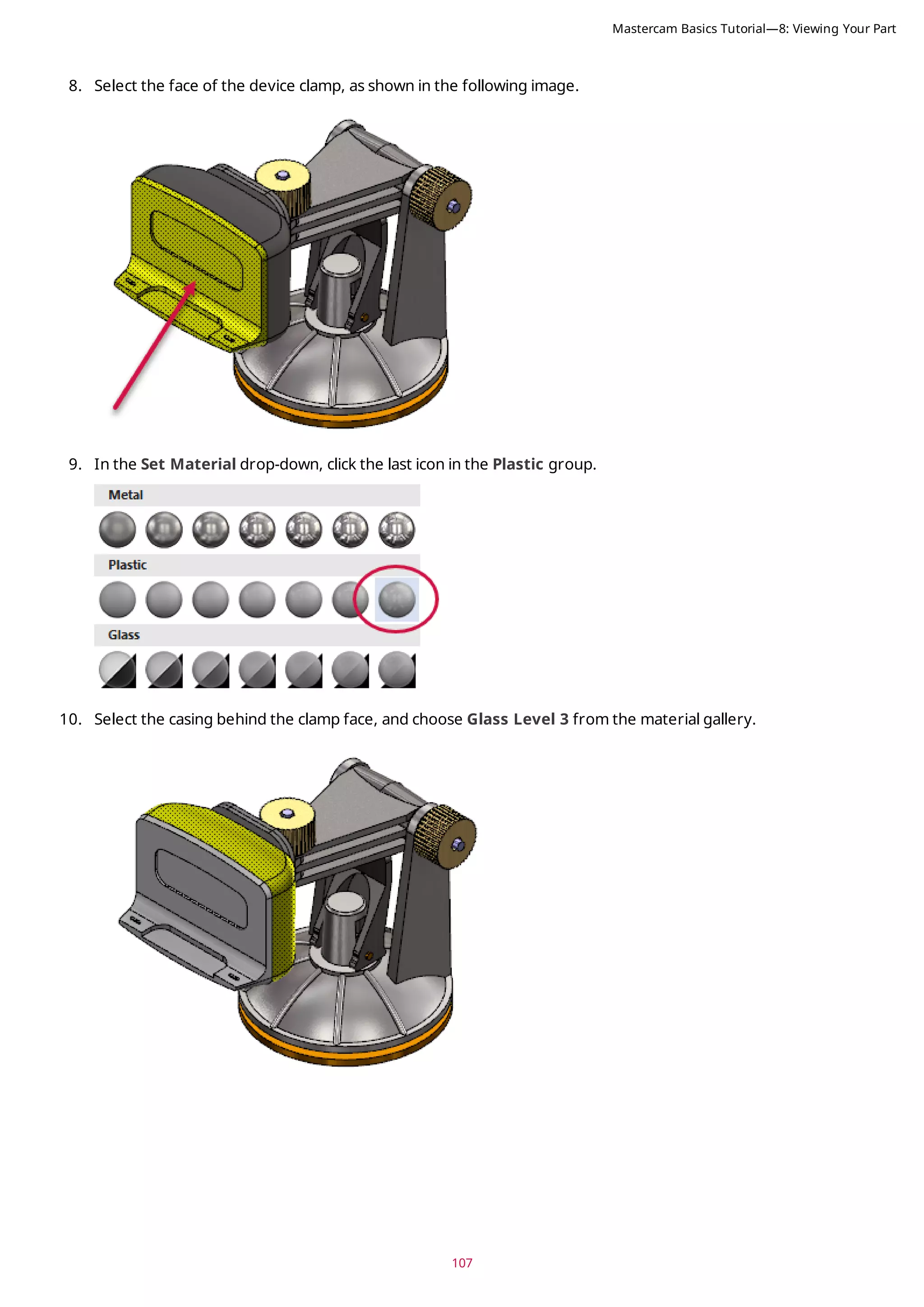
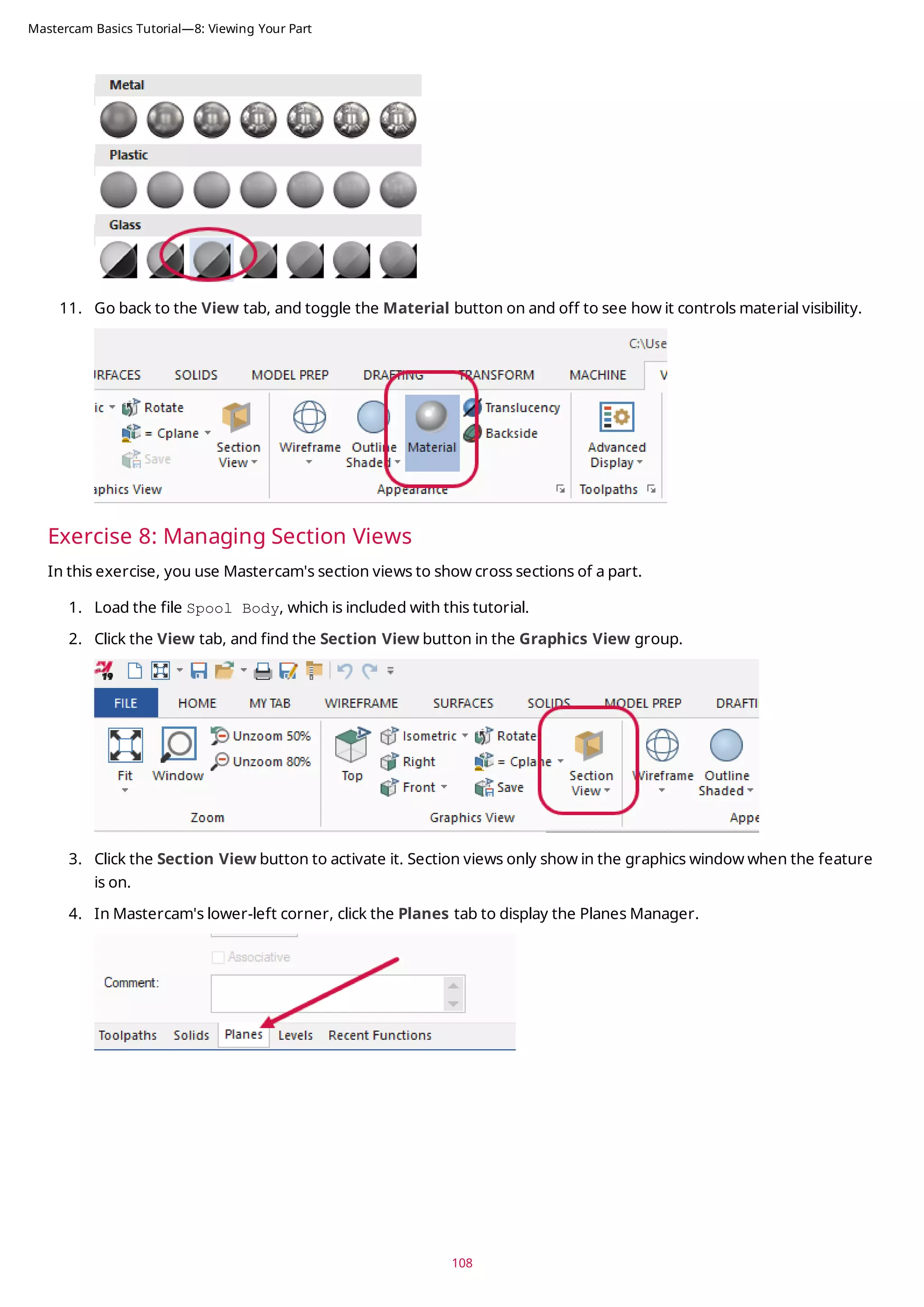
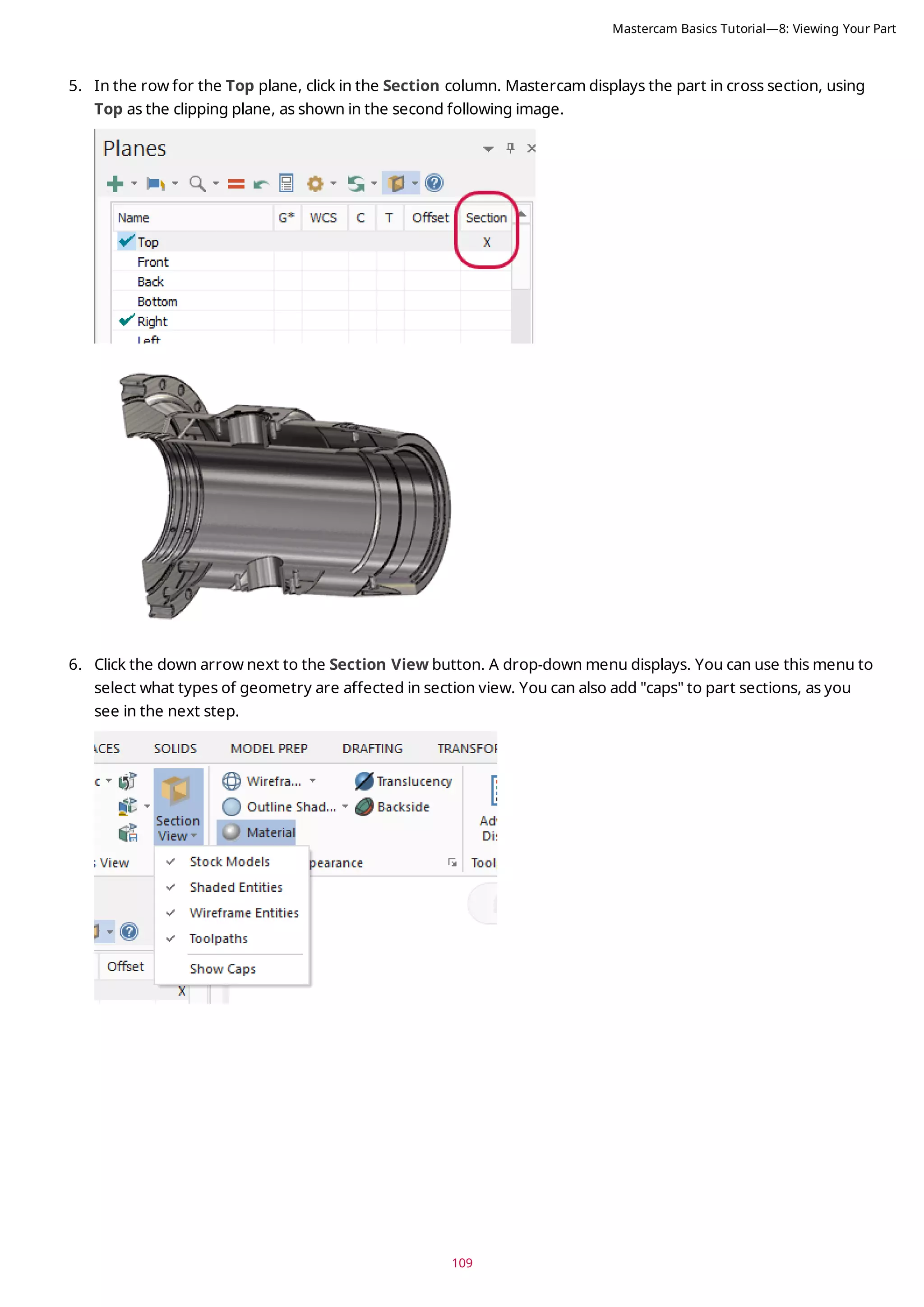
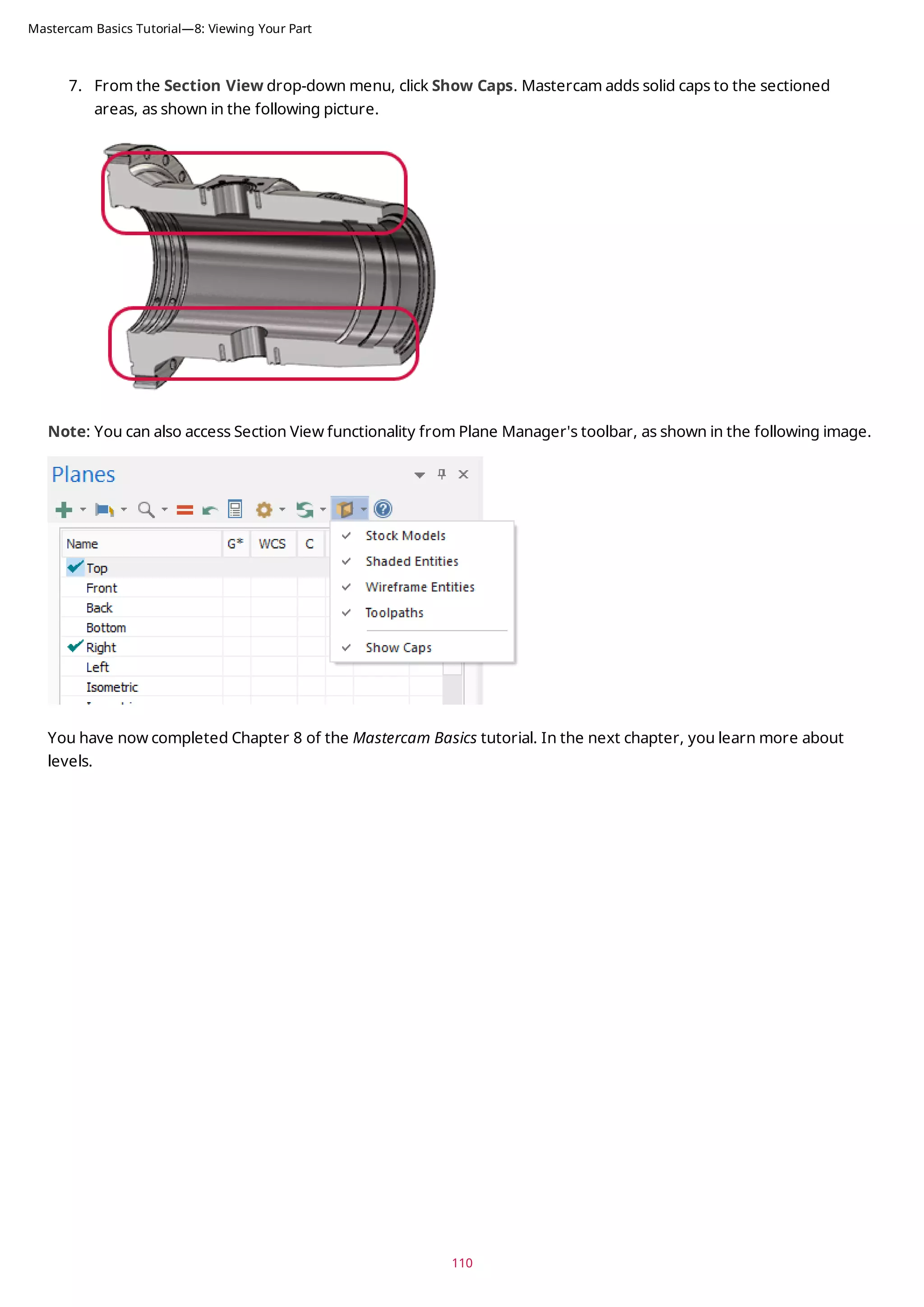
![CHAPTER 8
VIEWING YOUR PART
Mastercam provides several tools and methods for changing the appearance of the geometry and toolpaths in the
graphics window. In this lesson, you learn different ways of viewing your part, to hide portions of your part, and to
create and use Viewsheets.
Goals
l Fit all entities in the graphics window.
l Use zoom functions to magnify your view of selected entities.
l Dynamically rotate and pan entities in the graphics window.
l Create a Viewsheet.
l Blank and hide entities.
Exercise 1: Viewing All Entities
In this exercise, you set up your graphics window to view all entities in a Mastercam part file.
1. If necessary, open the tutorial part ANGLEBLOCK-MM. Change your view to Isometric, and press [F9] to show
the axes.
2. Choose Fit on the View tab or press [Alt+F1].
Fit and several other Zoom commands are also available in the right-click menu.
The part now fills the entire graphics window.
91](https://image.slidesharecdn.com/mastercam-basics-tutorial-220225044543/75/Mastercam-basics-tutorial-91-2048.jpg)
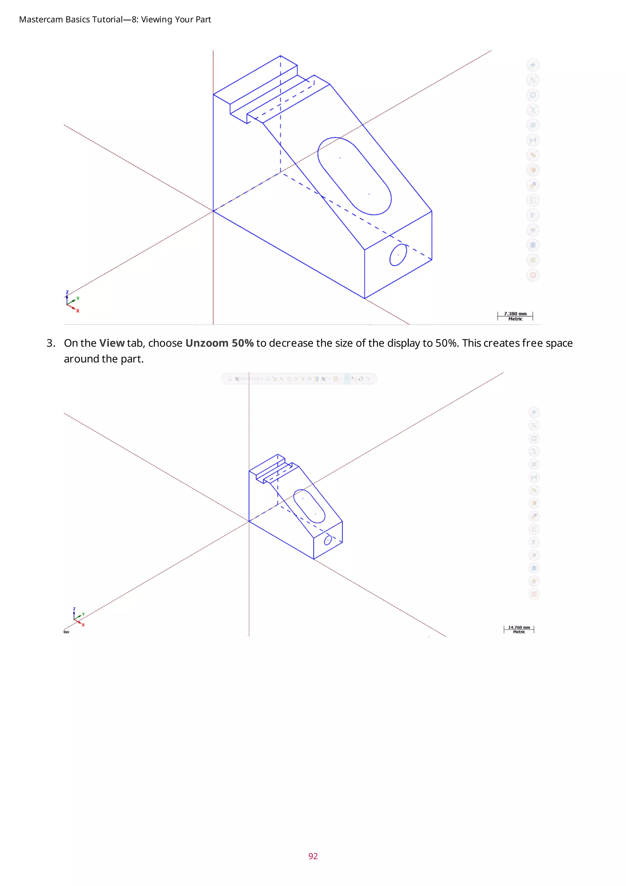
![93
Exercise 2: Zooming In and Out
In this exercise, you practice different techniques for viewing specific areas of detail in a Mastercam part.
1. Place your cursor in the upper left quadrant of the graphics window.
2. If your mouse has a middle mouse wheel, spin it back and forth to dynamically zoom in and out. You can also
press the [Page Up] and [Page Down] keys on your keyboard to zoom in and out.
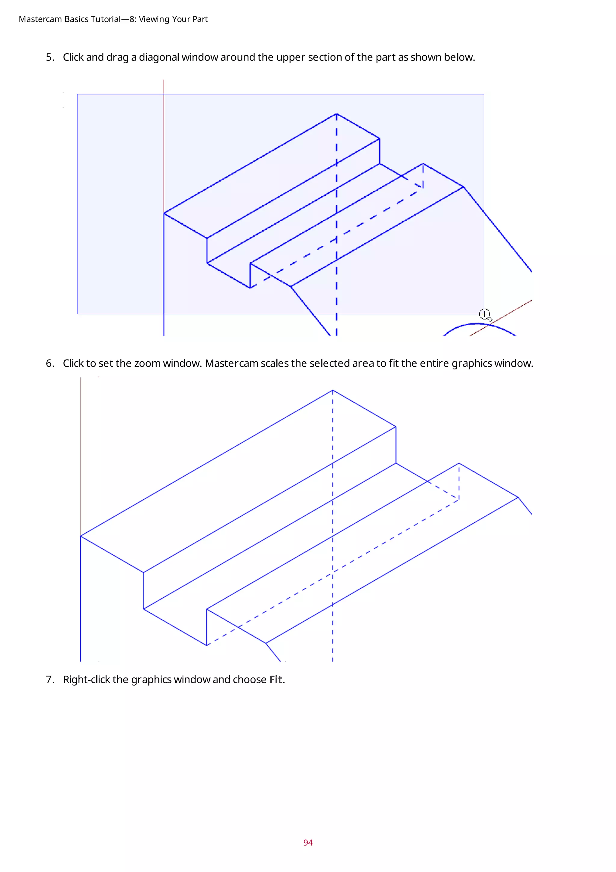
3. Click Fit or press [Alt+F1] to fit the part to the screen.
4. Choose Window.
Mastercam Basics Tutorial—8: Viewing Your Part](https://image.slidesharecdn.com/mastercam-basics-tutorial-220225044543/75/Mastercam-basics-tutorial-93-2048.jpg)
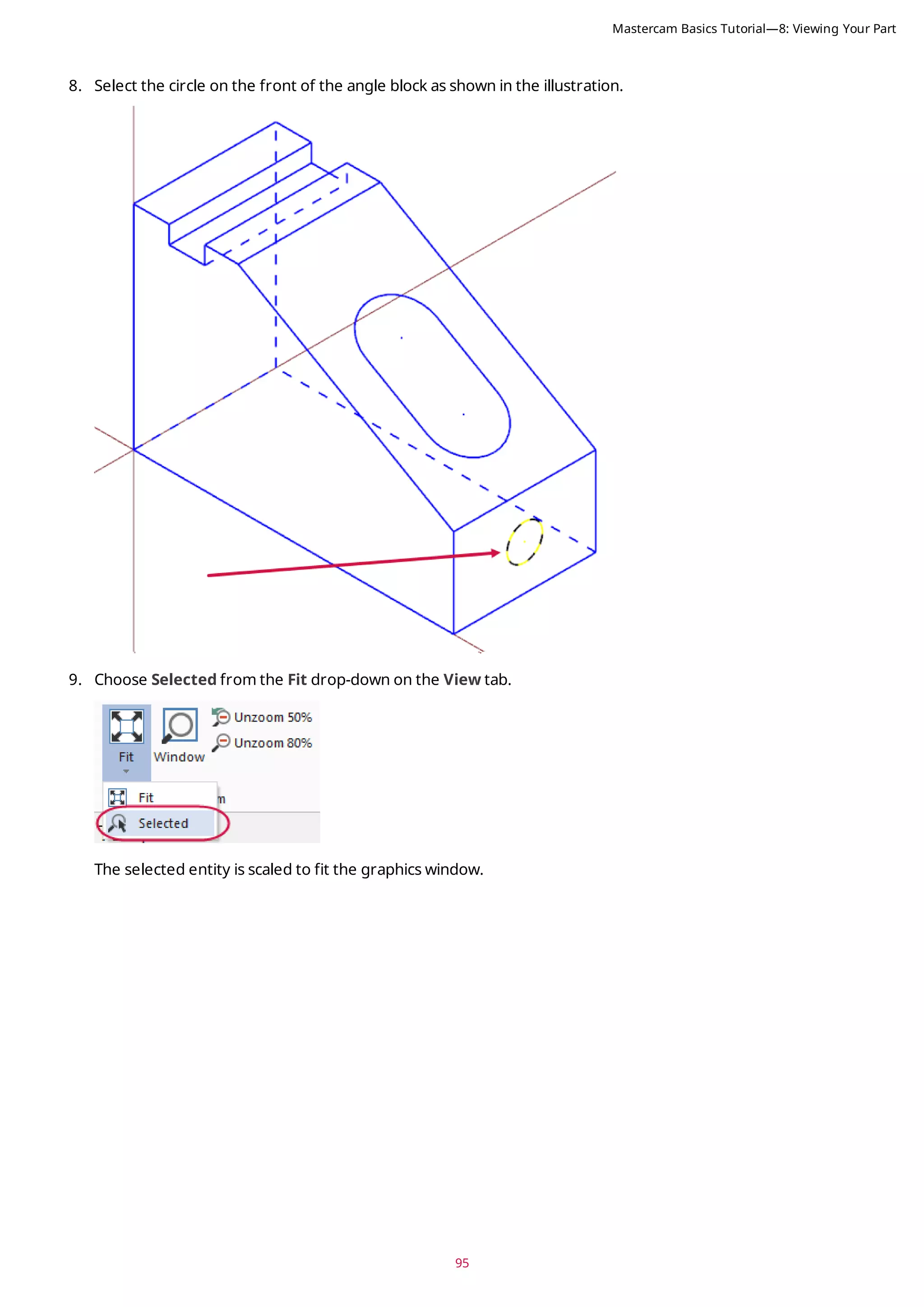
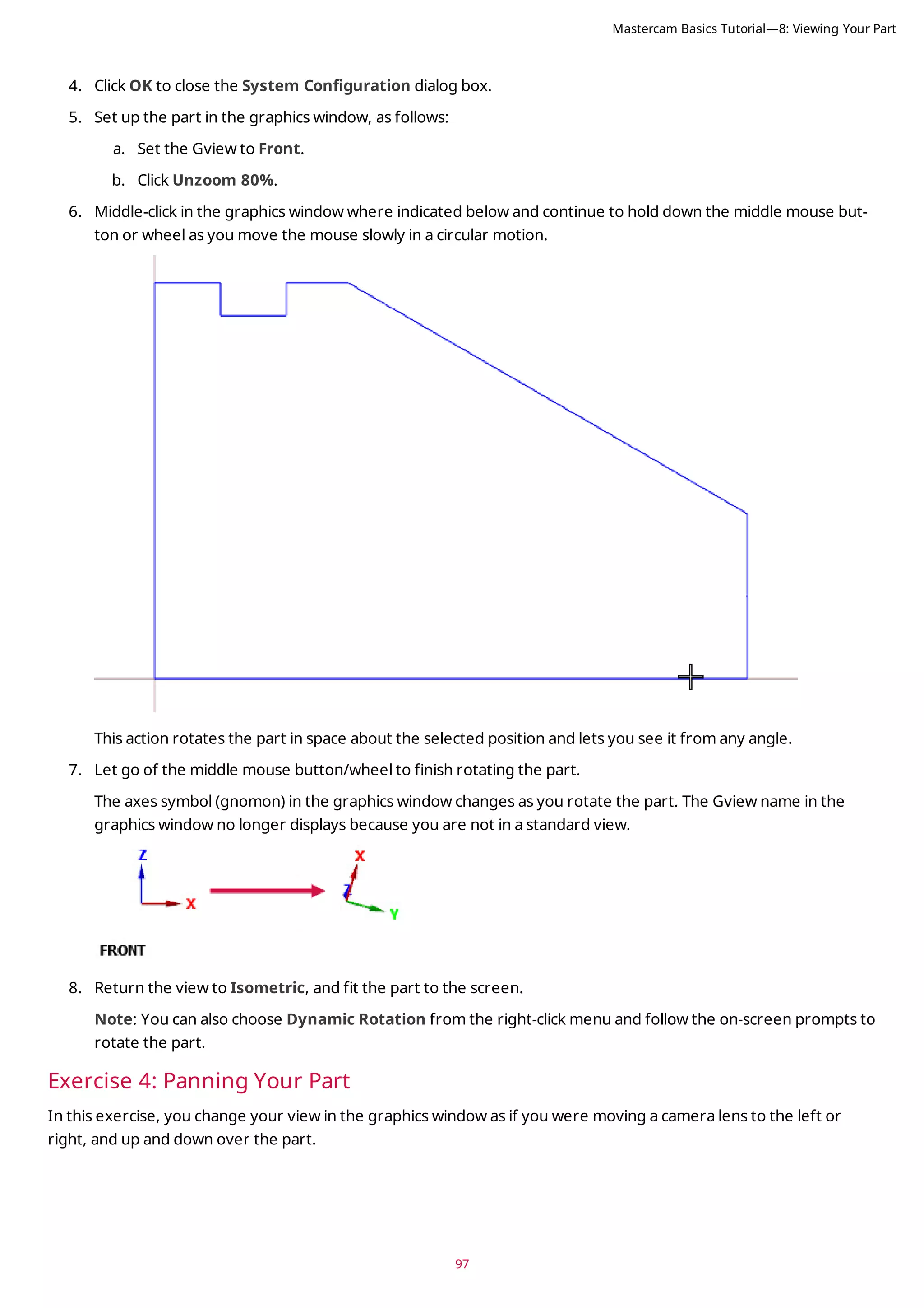
![10. Press [Esc] to clear the selection.
Exercise 3: Rotating Your Part View
This exercise shows how to set the preference for the action your middle mouse button or wheel performs in the
graphics window (rotate or pan). You also learn to dynamically rotate entities in the graphics window so that you can
see them from any angle.
1. Select File, Configuration to open System Configuration.
2. Expand the Screen group, and select View.
3. If necessary, set Middle button/wheel to Rotate.
By choosing Rotate, Mastercam sets dynamic rotation as the primary function when you click and hold the
middle mouse button or mouse wheel.
96
Mastercam Basics Tutorial—8: Viewing Your Part](https://image.slidesharecdn.com/mastercam-basics-tutorial-220225044543/75/Mastercam-basics-tutorial-96-2048.jpg)
![1. Hold down the [Shift] key, middle-click in the graphics window where indicated, and continue to hold down
the button/wheel while you move the mouse up, down, side to side, and around.
It appears that you have picked up the part and are moving it in the direction of the mouse. However, the
entities are not physically moved in space, only the display changes. The Gview does not change as you pan
the entities.
2. Release the [Shift] key while still holding down the middle mouse button/wheel and you can rotate the part.
Press the [Shift] again to return to panning.
3. When you finish panning, release the [Shift] key and the middle mouse button/wheel at the same time to exit
the function.
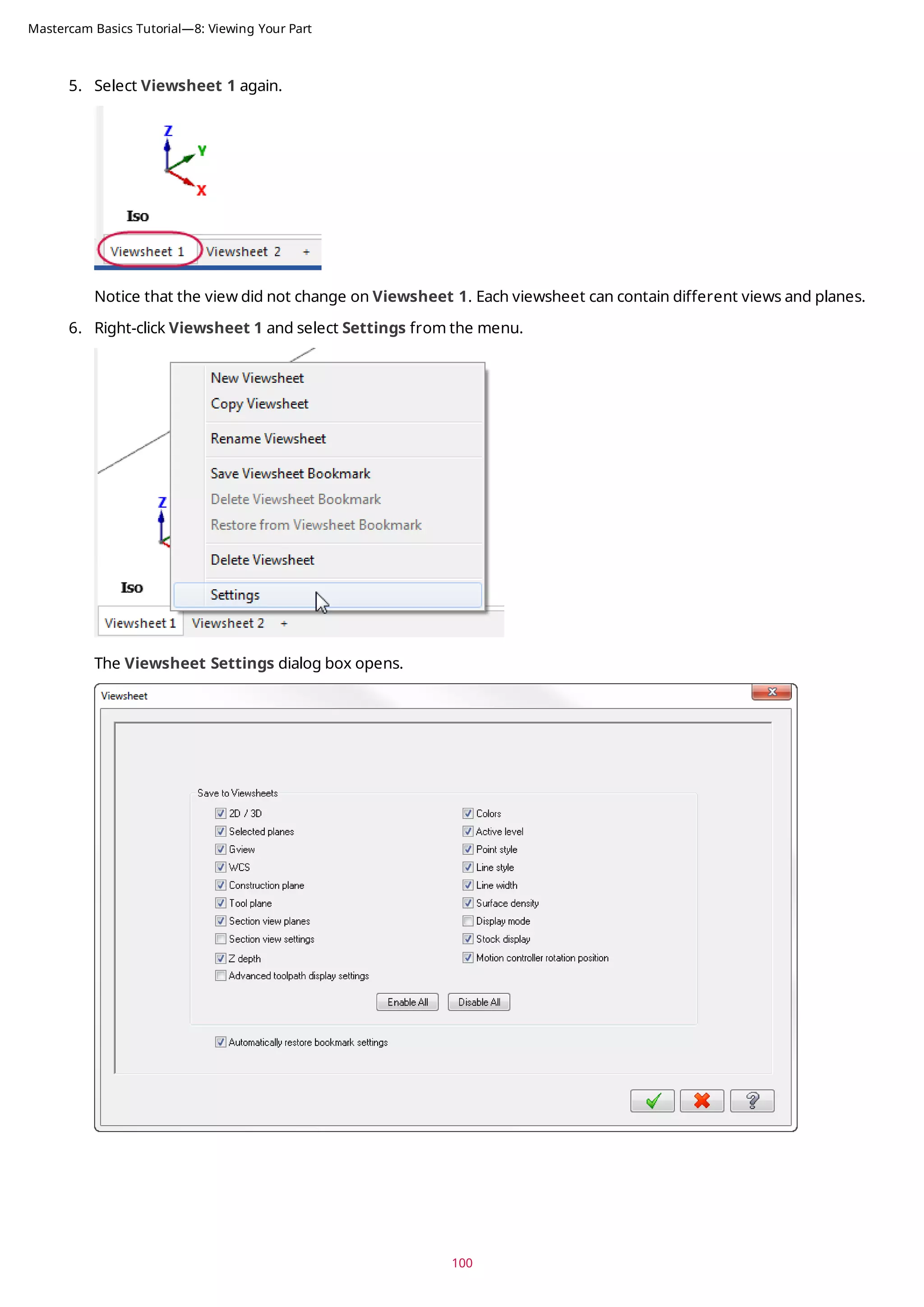
Exercise 5: Using Viewsheets
Mastercam allows you to view your part in different orientations by using viewsheets. Viewsheets make viewing a
large part easier, as you can set up multiple viewsheets with different views. Also, you can create a bookmark for
each viewsheet. A bookmark holds the settings for the view displayed in the viewsheet. When you save your part
file, Mastercam stores the viewsheet settings, including the bookmark, along with the part. When working with your
part, you can restore the viewsheet to its saved view by restoring the bookmark.
In this exercise, you create a viewsheet.
At the bottom of the graphics window, notice a tab named Viewsheet 1. This is the main view of your part and can-
not be deleted.
98
Mastercam Basics Tutorial—8: Viewing Your Part](https://image.slidesharecdn.com/mastercam-basics-tutorial-220225044543/75/Mastercam-basics-tutorial-98-2048.jpg)
![99
1. If necessary, fit the part to the graphics window, and set the view to Isometric.
2. Choose New in the Viewsheets group on the View tab. Alternately, you can right-click Viewsheet 1 and
select New Viewsheet from the menu.
3. Press [Enter] to accept the default name.
Viewsheet 2 is created and displayed next to Viewsheet 1.
4. Right-click in the graphics window, and select Right (WCS) to view the part on its right side.
Mastercam Basics Tutorial—8: Viewing Your Part](https://image.slidesharecdn.com/mastercam-basics-tutorial-220225044543/75/Mastercam-basics-tutorial-99-2048.jpg)
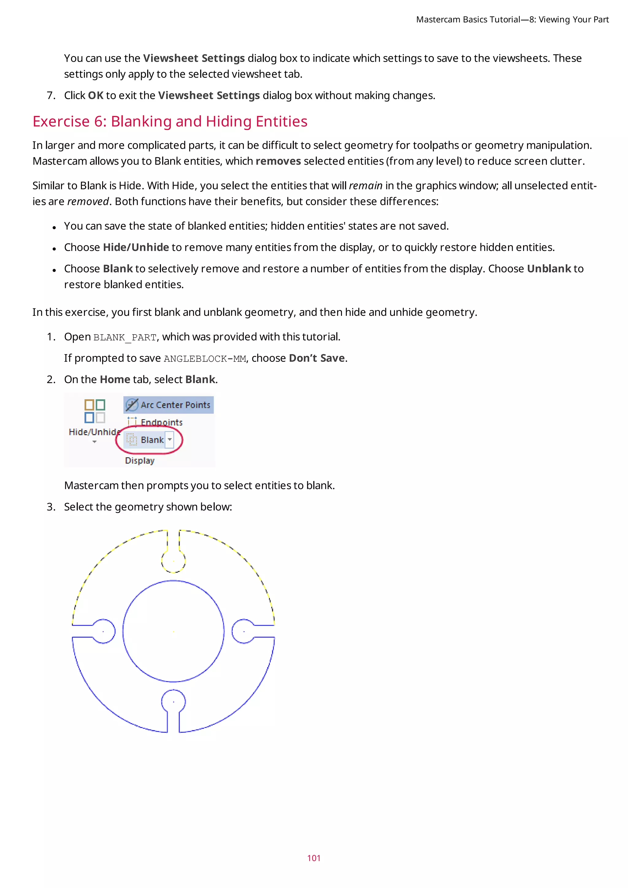
![4. Press [Enter] or choose End Selection located below the Selection Bar to accept the selections.
The selected geometry no longer displays in the graphics window.
Now, you unblank the geometry selected in the previous steps.
5. Select Unblank from the Blank drop-down.
The graphics window changes to display entities that have been blanked, so that you can select which ones to
unblank and which ones to keep hidden.
6. Select all of the blanked entities, and press [Enter]. The part should be whole again.
Next, you use the Hide/Unhide function.
102
Mastercam Basics Tutorial—8: Viewing Your Part](https://image.slidesharecdn.com/mastercam-basics-tutorial-220225044543/75/Mastercam-basics-tutorial-102-2048.jpg)
![103
7. Select Hide/Unhide.
Mastercam prompts you to select which entities to keep.
8. Select the geometry shown below:
9. Press [Enter] or choose End Selection to accept the selection.
The graphics window hides the unselected geometry.
Next, you unhide the geometry using Unhide Some.
Mastercam Basics Tutorial—8: Viewing Your Part](https://image.slidesharecdn.com/mastercam-basics-tutorial-220225044543/75/Mastercam-basics-tutorial-103-2048.jpg)
![10. Select Unhide Some.
Mastercam then prompts you to select entities to keep on the screen.
11. Select the geometry shown below:
12. Press [Enter] to accept the selections.
Mastercam unhides the selected geometry. Any geometry that was hidden and not selected remains hidden.
13. Click Hide/Unhide to show all entities.
104
Mastercam Basics Tutorial—8: Viewing Your Part](https://image.slidesharecdn.com/mastercam-basics-tutorial-220225044543/75/Mastercam-basics-tutorial-104-2048.jpg)
![5. Press [Enter] or choose End Selection located below the Selection Bar.
6. The Change Levels dialog box displays.
Note: You can also use general selection methods to pre-select entities before choosing the Change Level
option. When you pre-select entities, Mastercam does not prompt you to select additional entities and you
advance directly to the Change Levels dialog box.
7. In the Change Levels dialog box complete the following steps:
a. Choose Move.
b. Deselect the Use Active Level checkbox.
c. Type 4 in Number.
d. Click OK.
122
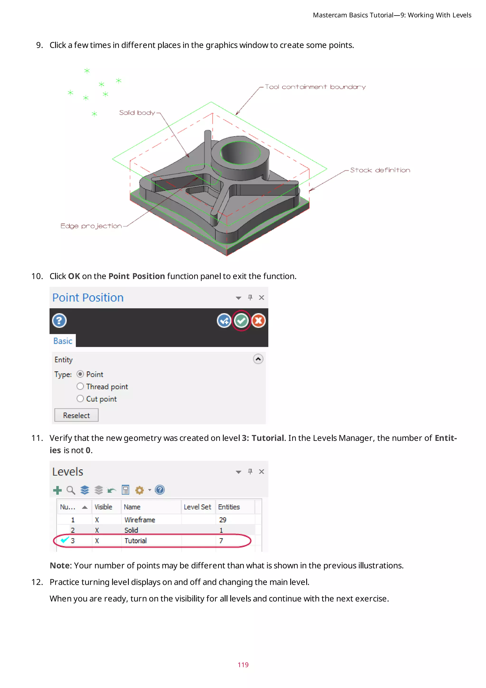
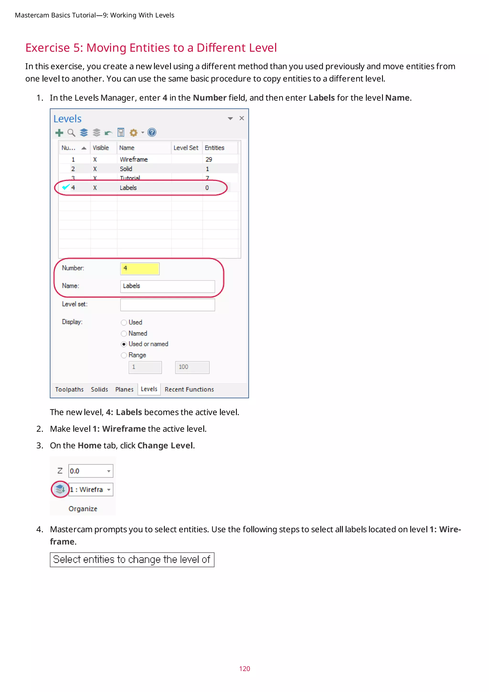
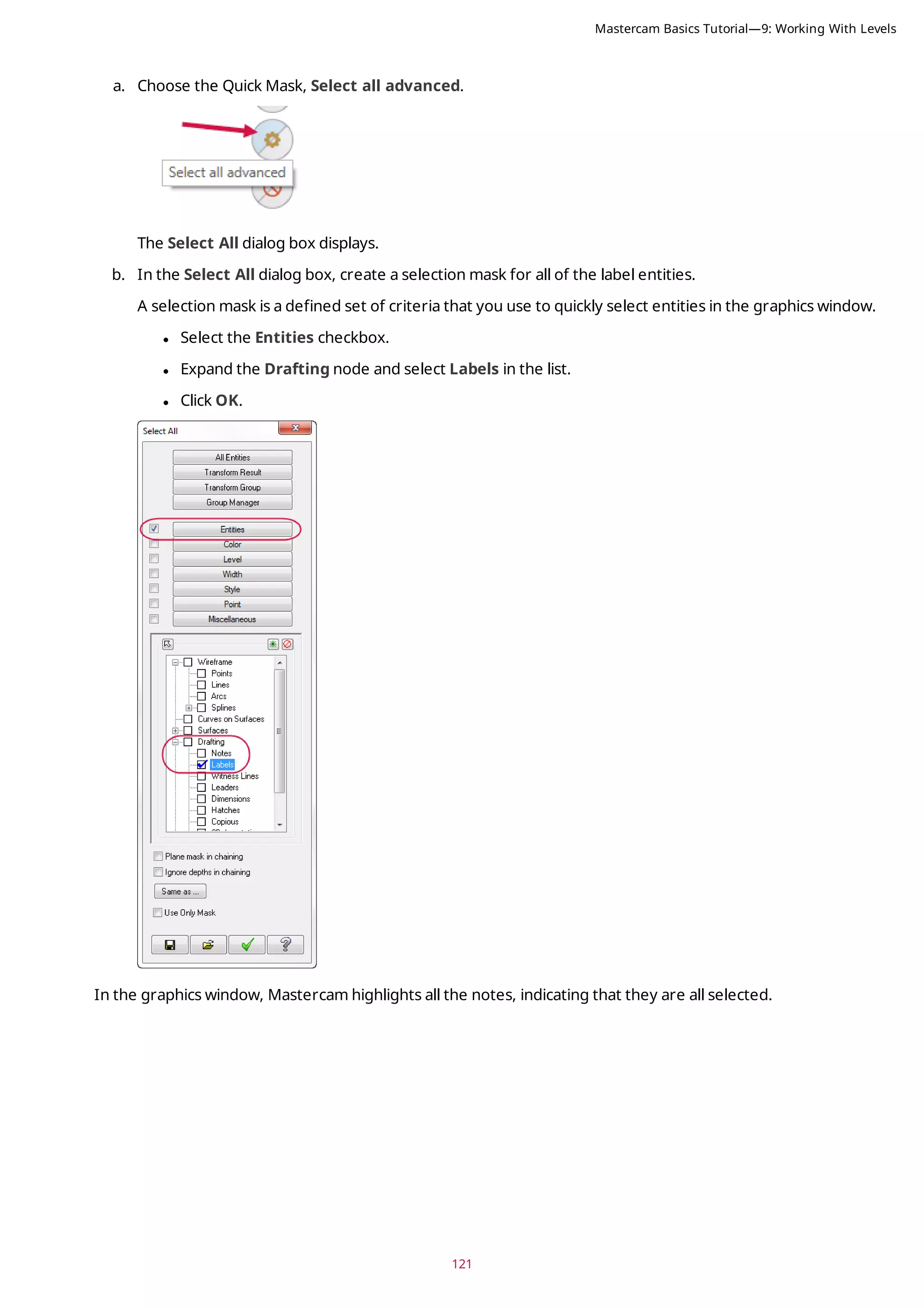
Mastercam Basics Tutorial—9: Working With Levels](https://image.slidesharecdn.com/mastercam-basics-tutorial-220225044543/75/Mastercam-basics-tutorial-122-2048.jpg)

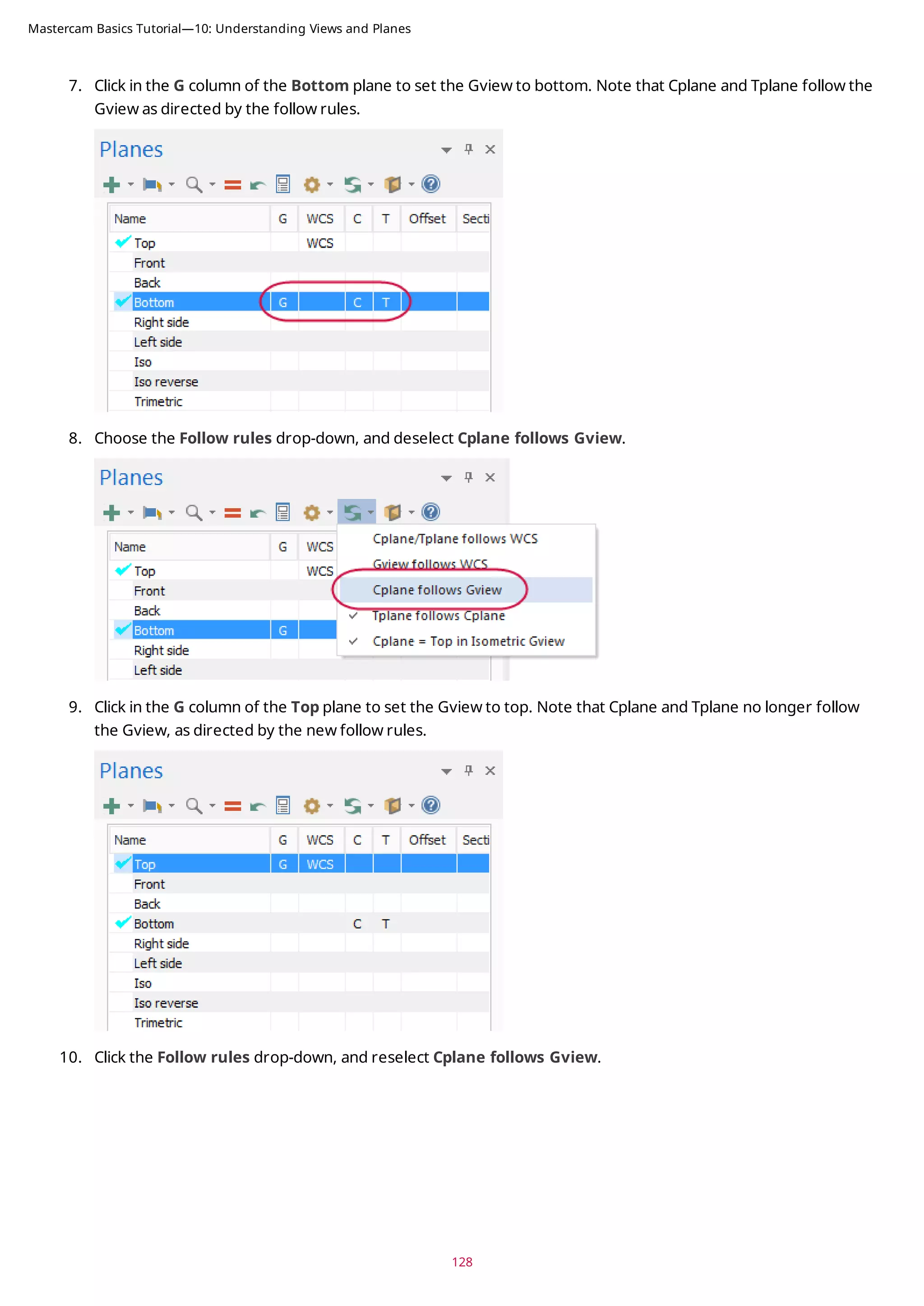
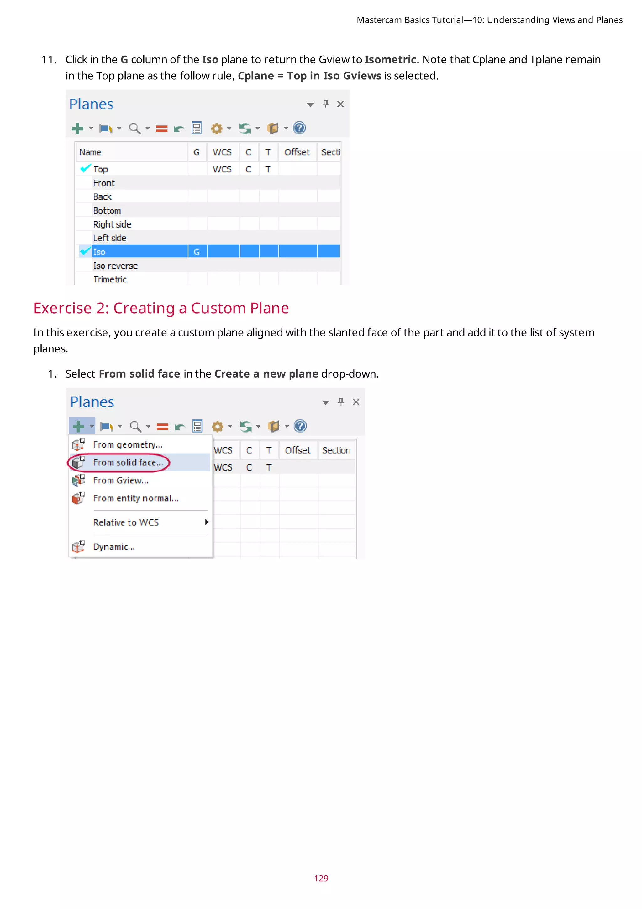
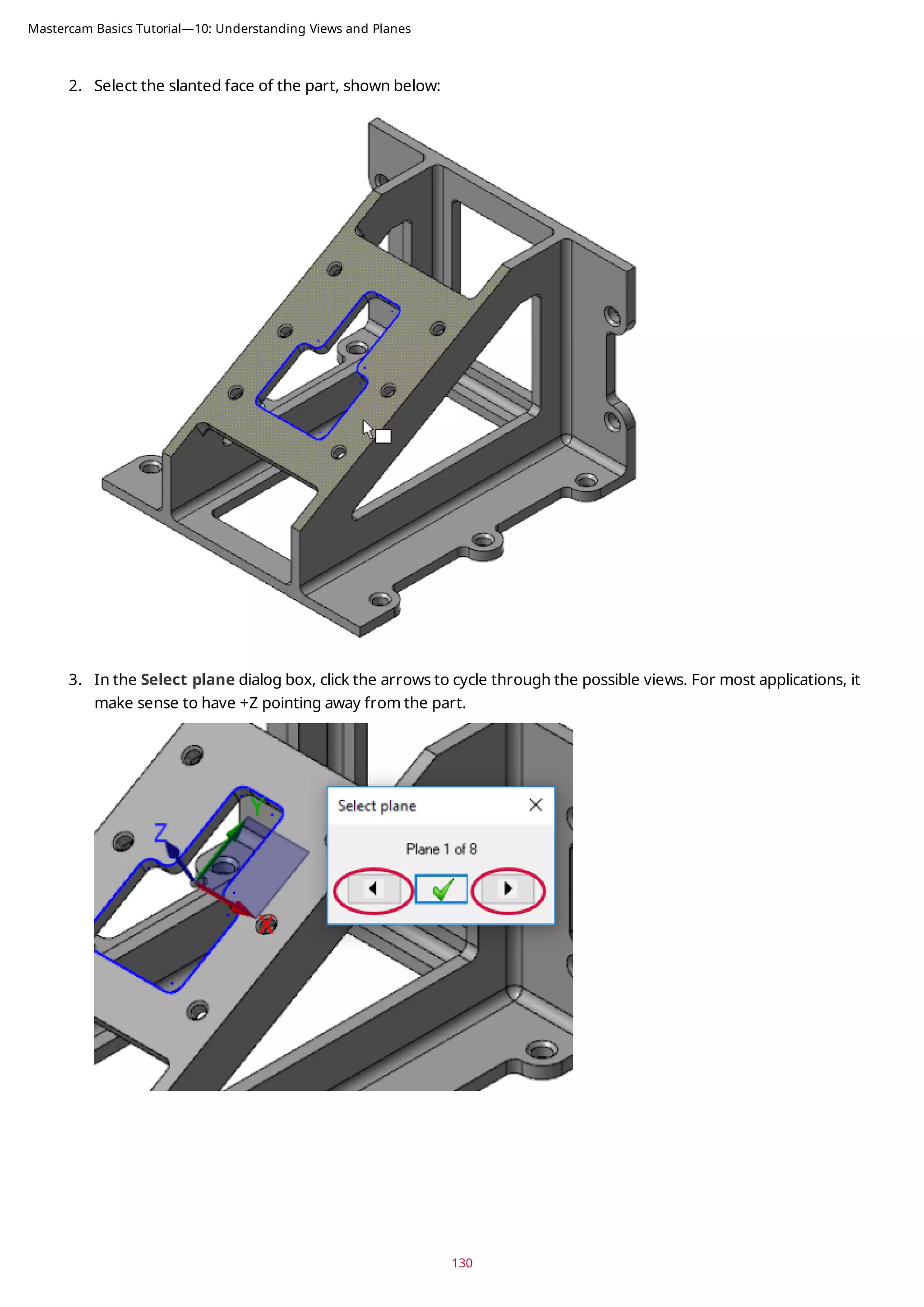
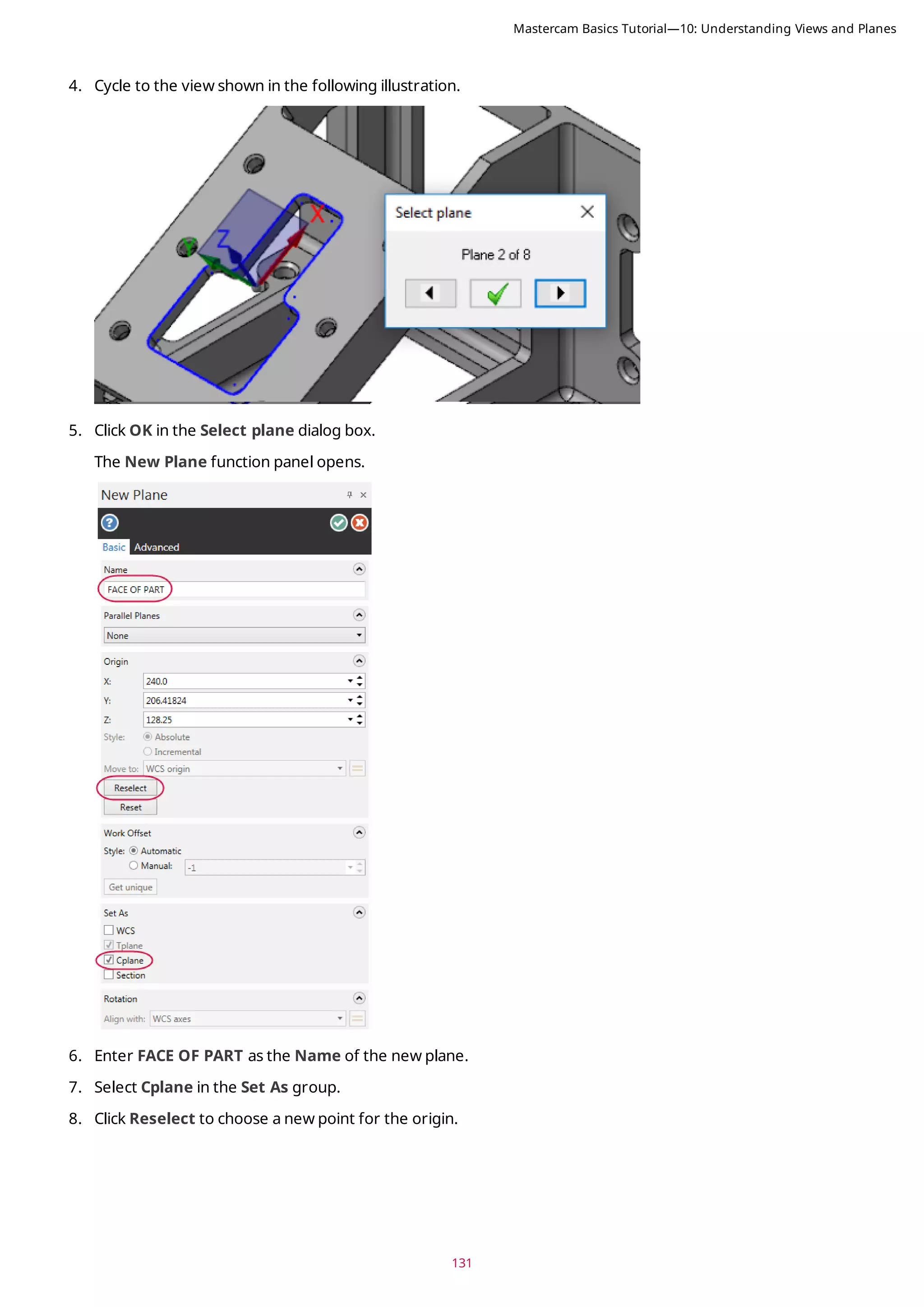
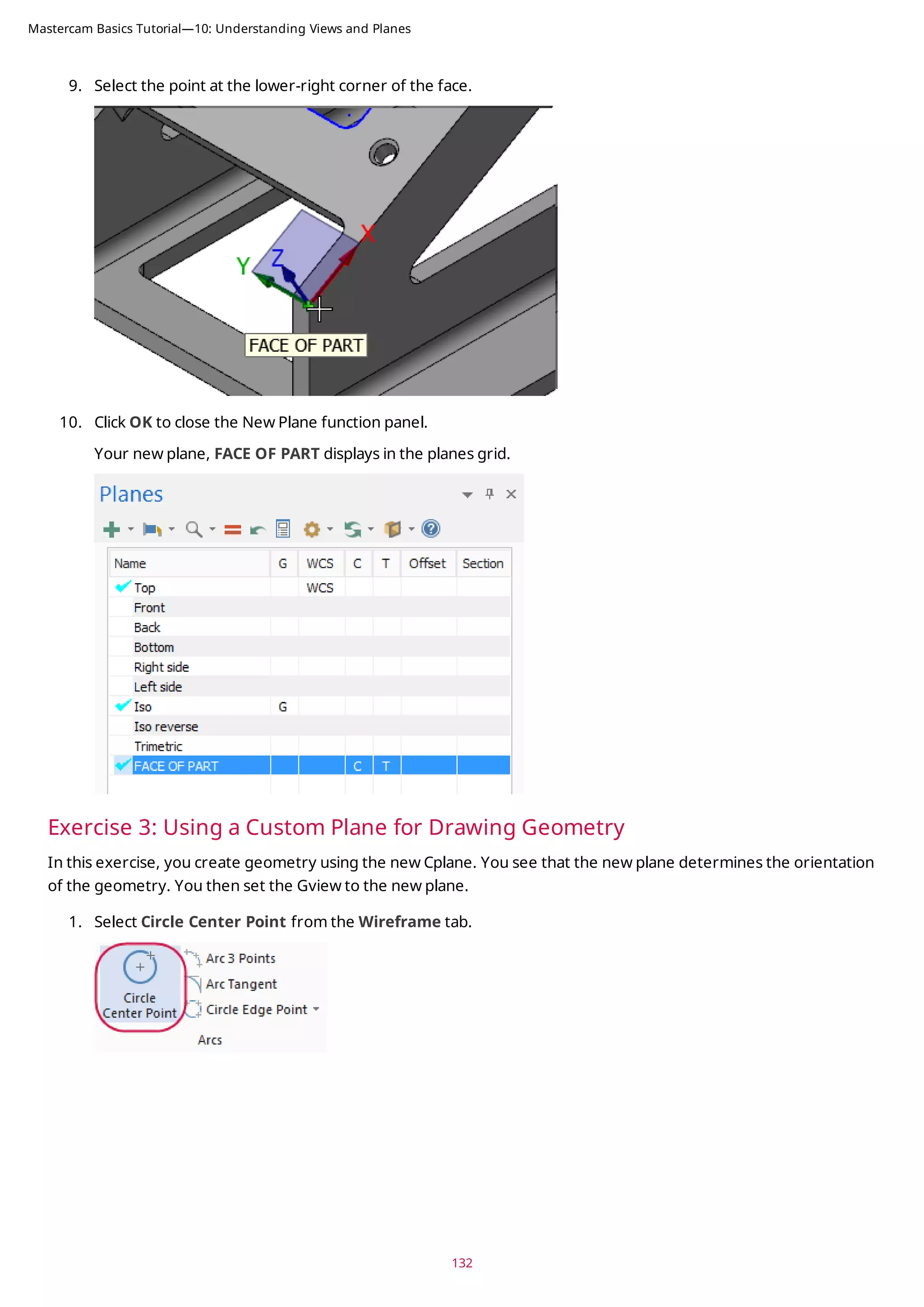
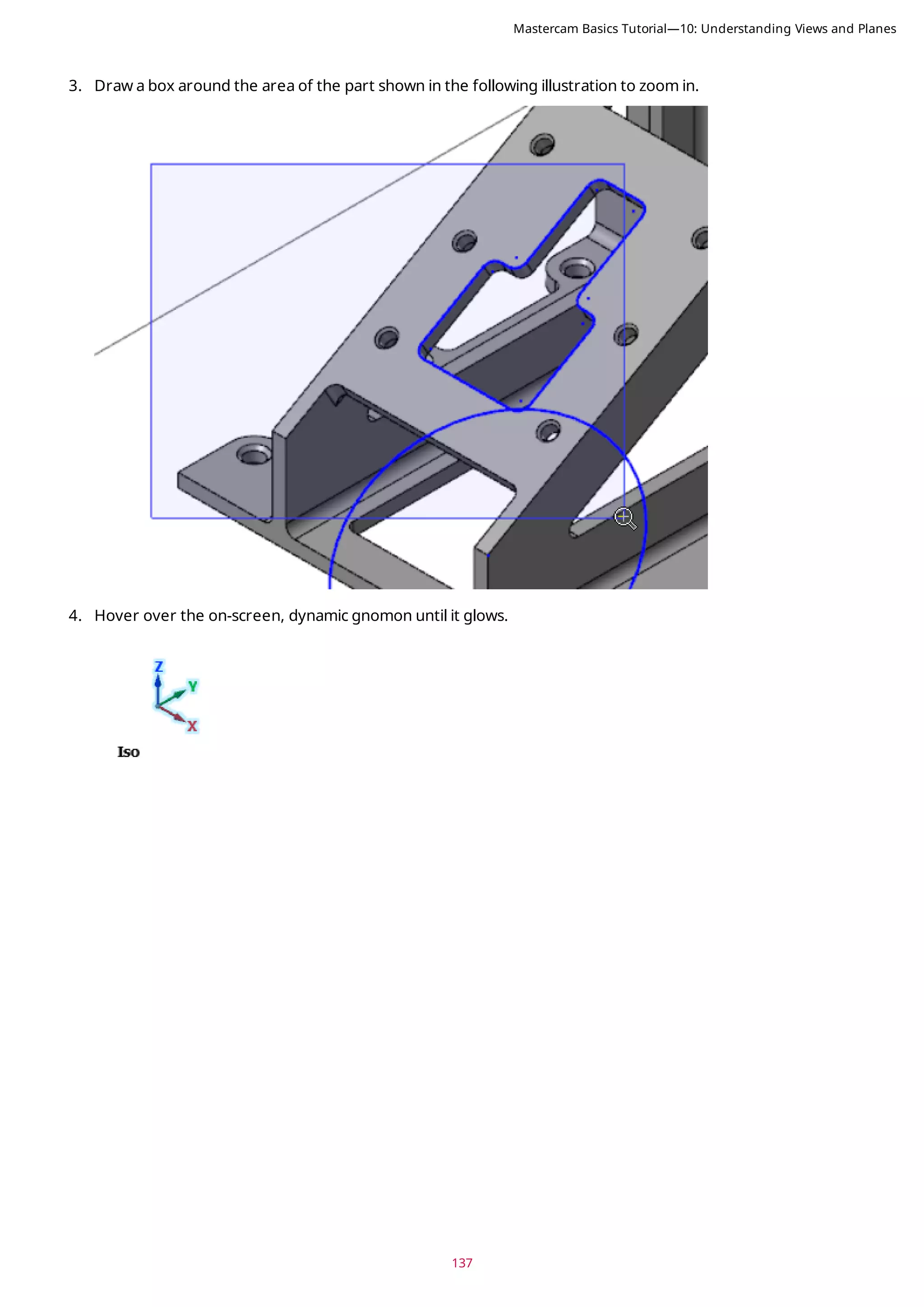
![135
5. If necessary, press [F9] to display the XYZ axes. Each axes type displays in a different color. Since Cplane and
Tplane are the same, the axes display as dotted lines. Experiment by turning individual axes on and off.
6. In the Planes Manager, click in the G column of the FACE OF PART plane to set the Gview.
Mastercam Basics Tutorial—10: Understanding Views and Planes](https://image.slidesharecdn.com/mastercam-basics-tutorial-220225044543/75/Mastercam-basics-tutorial-135-2048.jpg)
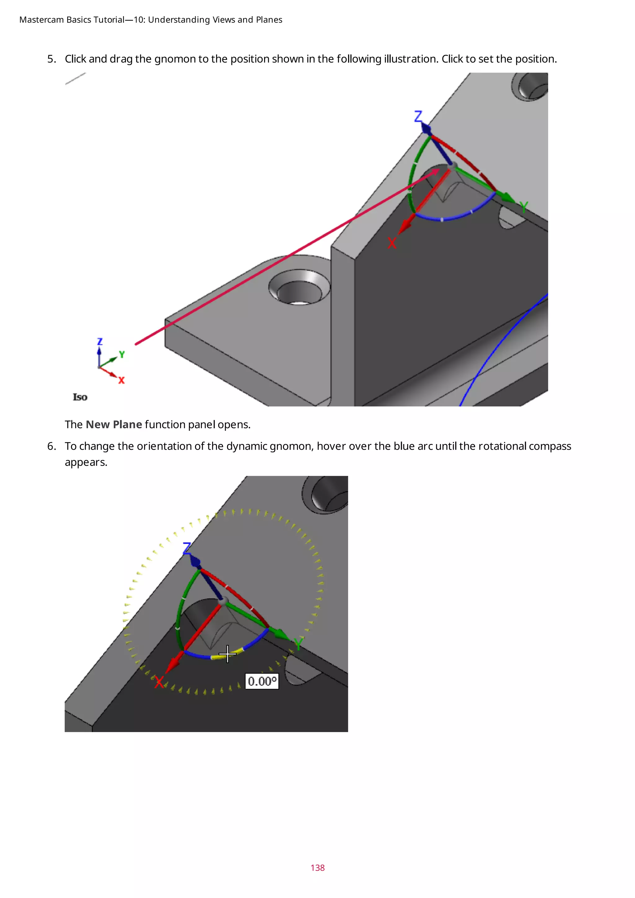
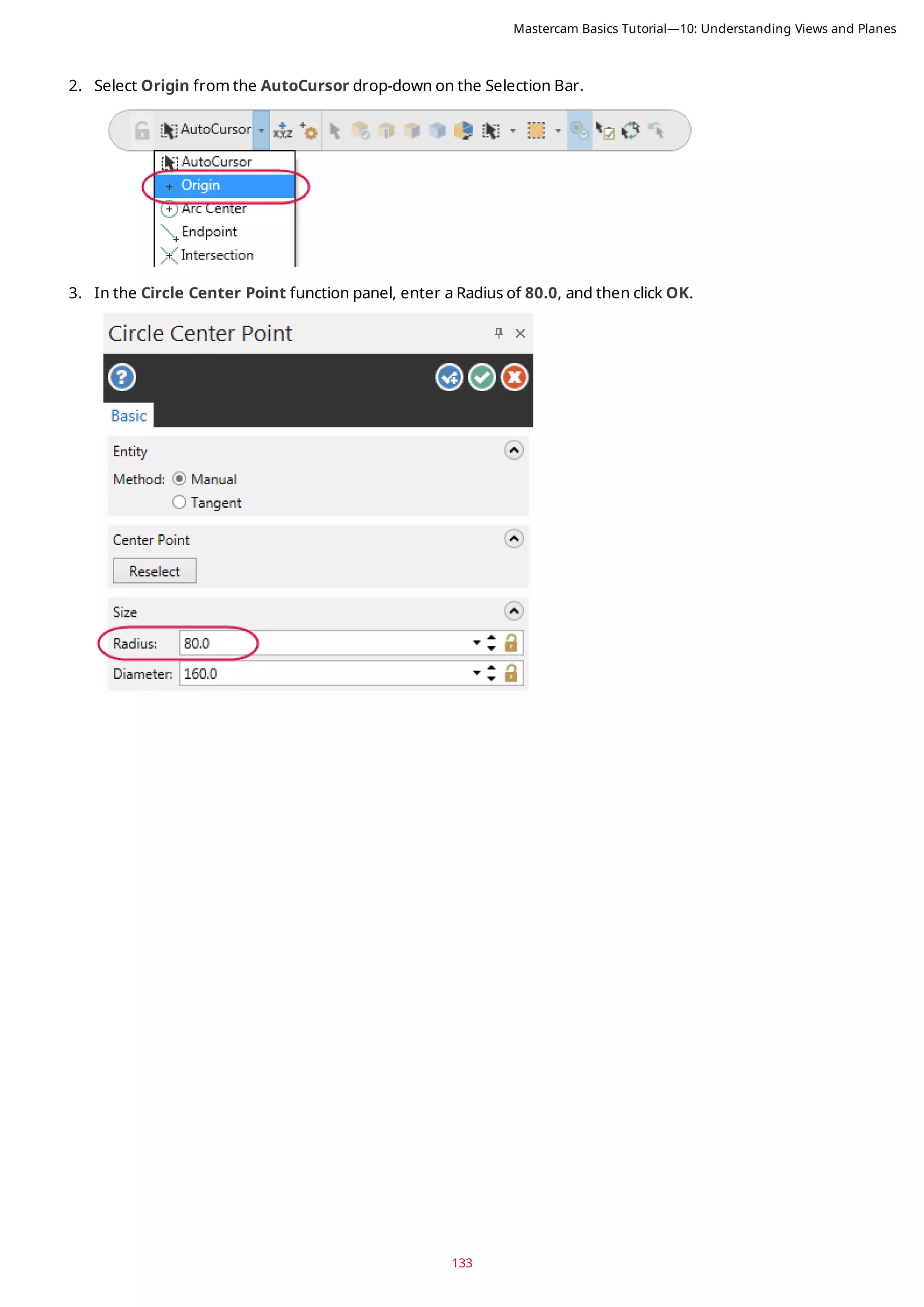
![139
7. Click the blue arc and rotate the gnomon from within the compass until it is at 90 degrees. Click to set the loc-
ation. (Rotating within the compass snaps in angular increments.)
Alternatively, you can enter 90 in the on-screen edit field, and press [Enter] twice.
Mastercam Basics Tutorial—10: Understanding Views and Planes](https://image.slidesharecdn.com/mastercam-basics-tutorial-220225044543/75/Mastercam-basics-tutorial-139-2048.jpg)

![143
CONCLUSION
Congratulations! You have completed the Mastercam Basics Tutorial! Now that you have mastered the skills in this
tutorial, explore Mastercam's other features and functions.
You may be interested in other tutorials that we offer. Mastercam tutorials are being constantly developed, and we
will add more as we complete them. Visit our website, or select Help, Tutorials from the File tab.
Mastercam Resources
Enhance your Mastercam experience by using the following resources:
l Mastercam Documentation—Mastercam installs a number of helpful documents for your version of software
in the Documentation folder of your Mastercam 2019 installation.
l Mastercam Help—Access Mastercam Help by selecting Help, Contents from Mastercam's File tab or by press-
ing [Alt+H] on your keyboard.
l Mastercam Reseller—Your local Mastercam Reseller can help with most questions about Mastercam.
l Technical Support—Our Technical Support department (+1 860-875-5006 or support@mastercam.com) is
open Monday through Friday from 8:00 a.m. to 5:30 p.m. USA Eastern Standard Time.
l Mastercam Tutorials—We offer a series of tutorials to help registered users become familiar with basic
Mastercam features and functions. Visit our website, or select Help, Tutorials from Mastercam's File tab to
see the latest publications.
l Mastercam University—Mastercam University, an affordable online learning platform, gives you 24/7 access to
Mastercam training materials. Take advantage of more than 180 videos to master skills at your own pace and
help prepare for Mastercam Certification. For more information on Mastercam University, please contact
your Authorized Mastercam Reseller, visit www.mastercamu.com, or email training@mastercam.com.
l Online Communities—You can find a wealth of information at www.mastercam.com. For tech tips and the
latest Mastercam news, follow us on Facebook (www.facebook.com/mastercam), Twitter
(www.twitter.com/mastercam), or Google+ (plus.google.com/+mastercam). Visit our YouTube channel to see
Mastercam in action (www.youtube.com/user/MastercamCadCam)! Registered users can search for inform-
ation or ask questions on the Mastercam Web forum, forum.mastercam.com, or use the knowledgebase at
kb.mastercam.com.
Contact Us
For questions about this or other Mastercam documentation, contact the Technical Documentation department by
email at techdocs@mastercam.com.
Mastercam Basics Tutorial—Conclusion](https://image.slidesharecdn.com/mastercam-basics-tutorial-220225044543/75/Mastercam-basics-tutorial-143-2048.jpg)


![Giáo trình NX Unigraphics [Tiếng Việt]](https://cdn.slidesharecdn.com/ss_thumbnails/giaotrinhugs-160304081230-thumbnail.jpg?width=640&height=640&fit=bounds)


![Sample x5-hbk-v3[1]](https://cdn.slidesharecdn.com/ss_thumbnails/sample-x5-hbk-v31-210524234813-thumbnail.jpg?width=640&height=640&fit=bounds)


![Moho Pro 14.4 Crack for MacOS Works Until 2050 [Latest] pptx](https://cdn.slidesharecdn.com/ss_thumbnails/softwareoverview-251207192639-797289c4-thumbnail.jpg?width=640&height=640&fit=bounds)
![AnyTrans for iOS 8.9.14.20251127 With Crack for MacOS [Latest] pptx](https://cdn.slidesharecdn.com/ss_thumbnails/softwareoverview-251207190907-2316965f-thumbnail.jpg?width=640&height=640&fit=bounds)
![Soundtoys Mac v5.5.5.0 Crack for MacOS Full Version [Latest] pptx](https://cdn.slidesharecdn.com/ss_thumbnails/softwareoverview-251207193711-91d8ae6b-thumbnail.jpg?width=640&height=640&fit=bounds)
![WinRAR Crack 7.13 Final Mac Keygen 2026 Download [Latest] Software.pptx](https://cdn.slidesharecdn.com/ss_thumbnails/software-251207185858-eb450678-thumbnail.jpg?width=640&height=640&fit=bounds)


![Chapter4_Initiation_of_Sediment_Motion_v2[1].pptx](https://cdn.slidesharecdn.com/ss_thumbnails/chapter4initiationofsedimentmotionv21-251208223747-f94ef163-thumbnail.jpg?width=640&height=640&fit=bounds)


