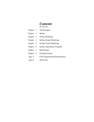
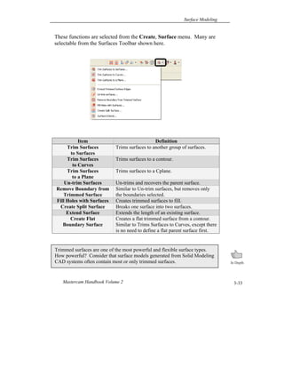
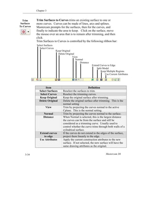
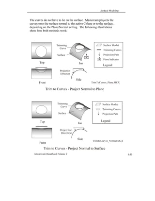
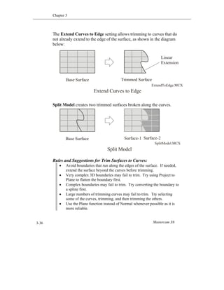
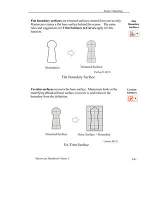
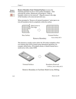
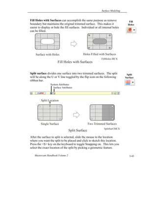
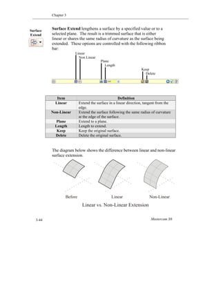
Mastercam Handbook Volume 2 for Mastercam X6
Copyright © 1984 - 2012 In-House Solutions Inc. - All rights reserved.
Software: Mastercam X6 Mill Level 3 & Solids
Authors: In House Solutions
ISBN: 978-1-926955-46-9
Revision Date: February 8, 2012
Notice
In-House Solutions Inc. reserves the right to make improvements to this manual at any
time and without notice.
Disclaimer of All Warranties and Liability
In-House Solutions Inc. makes no warranties, either express or implied, with respect to
this manual or with respect to the software described in this manual, its quality,
performance, merchantability, or fitness for any particular purpose. This In-House
Solutions Inc. manual is sold or licensed "as is." The entire risk as to its quality and
performance is with the buyer. Should the manual prove defective following its purchase,
the buyer (and not In-House Solutions Inc., its distributor, or its retailer) assumes the
entire cost of all necessary servicing, repair, of correction and any incidental or
consequential damages. In no event will In-House Solutions Inc. be liable for direct,
indirect, or consequential damages resulting from any defects in the manual, even if In-
House Solutions Inc. has been advised of the possibility of such damages. Some
jurisdictions do not allow the exclusion or limitation of implied warranties or liability for
incidental or consequential damages, so the above limitation or exclusion may not apply to
you.
Copyrights
This manual is protected under International copyright laws. All rights are reserved. This
document may not, in whole or part, be copied, photocopied, reproduced, translated or
reduced to any electronic medium or machine readable form without prior consent, in
writing, from In-House Solutions Inc.
Trademarks
Mastercam is a registered trademark of CNC Software, Inc.
Microsoft, the Microsoft logo, MS, and MS-DOS are registered trademarks of Microsoft
Corporation; Windows2000, Windows XP, Windows 7 are registered trademarks of
Microsoft Corporation.
This document complies with Mastercam X6 as of January 2012. Requires Mastercam Mill
Level 3 and Solids.
Contents
Introduction
Chapter 1 3D Workspace
Chapter 2 Splines
Chapter 3 Surface Modeling
Chapter 4 Surface Rough Machining
Chapter 5 Surface Finish Machining
Chapter 6 Surface High Speed Toolpaths
Chapter 7 Mold Project
Chapter 8 Prototype Project
App. A CNC Programming Planning Sheet
App. B Drill Chart
Introduction
The Handbook can be used as the primary resource for a Mastercam class,
as a self-study guide, or a shop reference. Mastercam help functions and
information on the student CD supplement the material in this book.
A unique feature of this book is the comprehensive, top-down approach it
takes to learning. Concepts and essential knowledge are included along
with practical applications. This approach means you not only learn how
to use Mastercam, but why things work as they do.
By understanding exactly what you are doing and why each step of the
way, you learn to recognize the best approach to problems. Not only will
you be better prepared to work effectively, you will gain a solid
foundation of knowledge that will help you continue to learn and adapt as
technology changes.
Specific recommendations about how to best use Mastercam are included.
There are often many ways to accomplish any task. However, you will
learn faster and understand the overall picture of what you are doing if you
first master fundamentals and standard practices.
In any case where information in this book conflicts with your machine
manuals or the methods used at your company or school, ignore the
suggestions in this book and use the information in the manuals and
established procedures at your facility.
Never operate a CNC Machine without having read and understood the
operator and programmer manual, and having received safety and
operator training by a qualified person on that machine.
Contents This book is divided into ten chapters. Each covers a specific knowledge
area. Following is a breakdown of the chapters and what you will find in
each:
Chapter 1: 3D Workspace explains the Mastercam 3D work environment.
Chapter 2: Splines shows how to create and machine splines. Spline modeling
and machining concepts are an essential foundation for surface modeling and
machining.
Chapter 3: Surface Modeling shows how to create and modify all types of
surfaces in Mastercam.
Chapter 4: Surface Rough Machining shows how to remove excess material
from a surface or solid model in preparation for finish machining.
Chapter 5: Surface Finish Machining shows how to finish machine surface and
solid models.
Chapter 6: Surface High Speed Toolpaths introduces concepts and principles
of high speed machining and how to use Mastercam’s advanced surface high
speed rough and finish toolpaths.
Chapter 7: Mold Project introduces basic mold concepts and terminology. A
simple two piece working plastic injection mold is made starting with prints.
Chapter 8: Prototype Project is an assignment that starts with a complex CAD
surface model. The model is prepared for machining and then rough and finished
machined.
App. A: NC Program Planning Sheet is a template used to document the
machining process.
App. B: Drill Chart
IconsIcons are used to alert, inform, and enhance your learning experience. The
following icons are found in the margins of the book:
Remember reminds you of important information that will help you work safely
and productively.
Tips are suggestions from experienced CAD/CAM users that will guide your
learning and use of Mastercam.
Step by Step are detailed instructions on how to use a specific function or
perform a task.
On the CD alerts you that a file exists on the CD included with this manual that
may be necessary for accomplishing a task.
Try It assigns a task you should be able to successfully complete before
proceeding further.
Warning is used to emphasize situations that can cause damage to machines,
property, bodily injury or death. Machining can be dangerous. Take these
warnings seriously and do not proceed unless you are certain your methods and
setup are completely safe.
In Depth are notes of interest that deepen your understanding and knowledge of
a topic.
Power User denotes tips that are likely only applicable to the highest level users
of Mastercam.
Conventions Key words and Mastercam menu items are shown in bold the first
time they are used. Columns on the outside edges of each page and
note pages at the end of each chapter provide ample space for taking
notes.
Useful tips, recommended settings, best practices, and detailed instruction
on the most important features are included when possible.
Extra credit exercises are included on the student CD in PDF format.
These will help build your skill to a higher level.
Common
Terms
The following terms are used throughout this book.
Left Click means to click once on the left mouse button.
Click means the same as left click.
Right Click means to click once on the right mouse button.
Scroll means to roll the mouse scroll wheel, or move the scroll index in a
list.
Options are Mastercam functions selected from the main menu.
Enter means to select the <Enter> key on your computer keyboard.
Press means to press on a keyboard key.
Choose means to select a menu option or button.
Open/Close means to open or close a dialog or information box.
Dialog Box is a window that opens to allow input of information and
setting of defaults.
Drop Down/Fly Out Menus are menus that expand down, left, right, or
up, to reveal more menu lists.
A Function is the same as a menu option or command.
Help means the Mastercam help files loaded with your software.
Surface Modeling
Mastercam Handbook Volume 2 3-1
Objectives
Introduction
This chapter shows how to model parts using surfaces. Upon
completion of this chapter, you should be able to do the following:
 Understand the difference between wireframe and surface geometry.
 Understand common surface definitions.
 Identify and create basic surfaces including Ruled, Lofted, Revolved, and
Draft.
 Recognize and create advanced surfaces including Swept, Net, Fence,
Trim, Fillet, and Offset surfaces.
 Create surfaces that blend plane, curve, or other surfaces.
 Recognize which surface type(s) are suitable given the wireframe geometry
and part feature requirements.
 Trim surfaces to a curve, plane, or other surfaces.
 Extend split and un-trim surfaces.
 Remove trim surface boundaries and fill holes in surfaces.
Wireframe geometry consists of lines, arcs, and splines. These entities
describe only the edges of the part. They contain no information about
what lies on the faces of the part between the edges.
To illustrate, use Analyze Dynamic and select the edge geometry of any
3D wireframe part. As you drag the mouse along the wireframe edges,
the system displays coordinates. Clicking on the faces of the part fails to
select the face and provides no geometry information.
While wireframe geometry includes enough information to model and
machine 2D parts, more complex ones, especially those with complex
and organic shapes, require more. These parts need information about
every point that lies on every face of the part. Surfaces and Solids
include face information required to model and machine these complex
3D shapes.
Surface Modeling
3
Chapter 3
Mastercam X63-2
CAD
Geometry
Types
There are three types of geometry used by CAD/CAM software:
 Wireframe
 Surfaces
 Solids
Geometry Type Description
Wireframe  Wireframe geometry consists of curves (lines, arcs,
points and splines) and points.
 Wireframe geometry includes information only about
the edges of a part.
 Wireframe models cannot be shaded.
 Wireframe geometry is adequate to model and
machine most prismatic or “2-1/2D” parts –where all
contours exist in flat planes.
Surfaces  A surface can be thought of as an infinitely thin shell
stretched over a wireframe.
 Surfaces can have a 3D shape with length and breadth,
but they have no thickness.
 Surface geometry includes information about the faces
and edges of a part.
 There are many types of surfaces; each suited to model
a specific type of shape.
 Surfaces are used to model complex, freeform
(organic) shapes common in the automotive, aircraft,
mold, and consumer goods industries.
Solids  Solids contain information about the edges, faces, and
interior of the part.
 Most mechanical parts are now designed using Solid
Modeling software, like Mastercam Solids®,
SolidWorks®, SolidEdge®, ProEngineer®, and others.
 Solids are able to model many parts, but some highly
sculpted shapes, like car bodies, are best modeled
using surfaces.
 All Solids start with profiles of wireframe geometry.
Surface Modeling
Mastercam Handbook Volume 2 3-3
Surfaces begin with wireframe geometry: lines, arcs, splines and points.
These entities form profiles, or curves, referred to as Drive Curves.
Depending on the surface type and shape, one, two or more drive curves
may be required to define a surface. These curves are revolved, swept,
or otherwise used to create the surface.
With some surface types, drive curves are referred to as running in the
Along or Across direction, depending on whether they run along or
across the predominate shape of the part.
UV curves are curves that run along and across the face of the surface at
regular intervals. UV lines are not geometric entities. They cannot be
selected for any purpose. They are simply used to help visualize the
shape of the surface when shading is turned off. The density, or number
of UV lines per surface, can be set for each surface before it is created.
A surface normal is a vector that points away from the surface at a 90-
degree angle at any particular point on the surface. The direction of the
normal can be, and often is, different for every position on the surface.
The surface normal is used for certain surface creation, manipulation,
and machining operations.
All surfaces can be thought of as having two sides; one that the normal
points away from and the opposite side. When shading is not active, the
normal side is colored. The opposite side is dull gray.
The surface normal can be displayed using Analyze Dynamic. The
normal can be flipped from one side to the other using the Edit, Set
Normal or Change Normal functions.
Surface
Terms
Chapter 3
Mastercam X63-4
The following illustration shows all common surface terminology.
Item Definition
Drive Curves Curves used to define the surface.
UV Curves Used to help visualize the shape of the surface when
shading is not active. UV lines are not selectable
geometry, but are for display only.
Surface
Normal
A vector that points away from the surface at a 90 degree
angle all around at any particular point on the surface.
Shading Shading provides a photorealistic rendering of surface and
solid models. It can be turned on/off using Alt-S or the
shading toolbar.
Translucent A shading mode that allows you to partially see through
the shaded object.
Surface Shaded
Surface Normal
Surface Terms
Drive Curves
UV Curves
Legend
Surface Modeling
Mastercam Handbook Volume 2 3-5
Many different types of surfaces have been developed. Each uses a
different mathematical model to describe a certain type of shape.
Surfaces may have different wireframe geometry requirements and offer
relative strengths and weaknesses compared to other surface types.
While some shapes can be modeled using different types of surfaces,
often only one is best suited for that shape.
Recognizing which surface to use in a given situation, and how to build
that surface, is a skill. This skill is developed by first understanding
each surface type, its potential applications, and its relative strengths and
weaknesses. It takes practice to develop an eye for recognizing which
surfaces to use and to acquire the skills needed to create them.
Surfaces supported by Mastercam are shown in the menus below.
Surface
Types
Chapter 3
Mastercam X63-6
Ruled surfaces are created by linearly blending between two or more
contours. Think of this as making the shape by creating evenly spaced
lines between the two curves.
These curves can be made up of lines, arcs, splines or points. Most
ruled surfaces use two curves to define the surface. Notice that the UV
curves along the ruled surface are linear.
Consider using a Ruled surface to model a shape that could be formed by
drawing equally spaced lines between two or more curves.
Surface Shaded
Drive Curves
Ruled Surface
Contour-1
Contour-2
Ruled-1.MCX
UV Curves
Legend
Ruled
Surface
Surface Modeling
Mastercam Handbook Volume 2 3-7
Created Ruled / Lofted Surface
Follow the steps below to create a simple ruled surface. This example
uses the file, Ruled - 1.MCX, which is included on your student CD,
Step 1: Select the Create Ruled / Lofted Surface function from the
main menu or the Surfaces toolbar.
Step 2: Select the Ruled setting on the Create Ruled / Lofted
Surface ribbon bar.
Step 3: Chain Curve 1 and then Curve 2. Be sure to pick the curves
from the same side so they chain in the same direction or the surface
will be twisted. Close the Chain Manager and then select OK or
Apply on the Ruled/Lofted surface toolbar.
Ruled
Surface
Ruled
Lofted
Twisted Surface
Contour 2
Contour 1
Chapter 3
Mastercam X63-8
One of the curves for a ruled surface can be a point entity. This blends
the curve as shown in the example below. Simply select the Point
option in the Chaining dialog box and pick the point.
Rules and Suggestions for Ruled Surfaces:
 Always select both drive curves in the same direction. If you select in
opposite directions, the surface will be twisted.
 Turn shading on to make it easier to see any errors in the surface.
 Very complex drive curves can cause problems creating the surface.
Consider using partial chains to model the shape with two or more ruled
surfaces instead of one. In other words, create the shape using several
simple surfaces rather than one complex surface.
 Sharp corners in drive curves will sometimes be ignored. Mastercam will
display a warning in this case. Consider creating the shape using multiple
ruled surfaces or using the Chaining Option, Sync mode. Sometimes
putting a small fillet radius (.001-.005 inches) on sharp corners will cause
the surface to transition smoothly along the curve. Sync mode is covered
under Draft Surfaces in this chapter.
Rule
To Point
Rule Curve to Point
Point
Curve
RuleToPoint.MCX
Surface Modeling
Mastercam Handbook Volume 2 3-9
A Lofted surface is similar to a Ruled surface except blending between
the curves uses splines instead of lines. This creates a surface that flows
smoothly between multiple curves.
Lofted surfaces are used extensively in the boat building and aircraft
industry. Examples of parts that use lofted surfaces include wings,
propellers, turbine blades, and boat hulls.
Lofted surfaces have three or more drive curves, called Lofting Sections
or Lofting Stations, which are usually parallel to each other. A lofted
surface with only two drive curves would be the same as a ruled surface,
since there would be only two node points on the blending splines,
making them linear.
Consider using a Lofted surface when the drive curves are cross sections of
the resulting shape, and the shape can be formed by blending splines equally
between these sections.
Lofted
Surface
Lofted Surface
Surface Shaded
Lofting Sections
UV Curves
(Spline Blending)
Legend
LoftWing.MCX
Chapter 3
Mastercam X63-10
Rules and Suggestions for Lofted Surfaces:
 The same tips for ruled surface drive curves apply for lofted Surfaces.
 Cross sections should exist on the same Cplane. If needed, use the Xform
Project, Plane function to force all entities in a cross section to the same
plane.
 Chain all drive curves in the same direction or the surface will twist.
 For problems with spline drive curves, check for excess node points and
consider removing excess nodes.
 If the problem persists, use Analyze Dynamic to check for nodes that
incorrectly reverse the spline abruptly. Re-create the spline if all else fails.
A revolved surface is created by spinning a profile about a line, called
the axis of revolution. This line must exist before the revolved surface
function is selected.
Revolved
Surface
Revolved Surface
RevolveSurf.MCX
Surface Shaded
Profile
Axis of
Revolution
UV Lines
Direction Symbol
Legend
Surface Modeling
Mastercam Handbook Volume 2 3-11
Revolved surfaces are controlled by the ribbon bar shown below.
Angles are in reference to the construction plane (Cplane) that the
profile lies in, as shown in the graphic below.
Item Definition
Profile The curves to be revolved.
Axis The axis of revolution. An existing line that the profile will
be spun around.
Flip Flip direction of revolution.
Start Angle Degrees of rotation where the surface begins, in relation to
the plane that the profile resides in.
End Angle Degrees of rotation where the surface ends.
Revolved Surface Start/End Angles
Start Angle = 180
End Angle = 360
Start Angle = 0
End Angle = 180
End Angle
Start Angle
Flip
Axis
Profile
Chapter 3
Mastercam X63-12
Create Revolved Surface
Follow the steps below to create a revolved surface. This example uses
the file, Revolved Surface.MCX, which is included on your student
CD.
Step 1: Select the Create Revolved Surfaces function from the main
menu or the Surfaces toolbar.
Step 2: Chain the profile to revolve, and then select the axis of
revolution.
Step 3: Enter the Start Angle and End Angle. Use Flip to toggle
between the angles entered and their inverse. Select Apply or OK
when done.
Revolved
Surface
End Angle
Start Angle
Flip
Axis
Profile
Surface Modeling
Mastercam Handbook Volume 2 3-13
Rules and Suggestions for Revolved Surfaces:
 Multiple entities in the profile curve will result in multiple revolved
surfaces.
 To create a single revolved surface, use the Create curves spline function to
convert the curves to a spline before creating the surface.
 Revolved surfaces are very efficient types. Consider using a revolved
surface to create rounded corners like those shown below, rather than using
more complex surface types.
Use a Revolved surface when the shape can be formed by spinning a profile
around a line.
Cross section cuts taken of revolved surfaces along the axis of revolution are
arcs. Toolpaths created across revolved surfaces may take advantage of
machine G18/G19 arc commands, significantly reducing G-code file size.
RevolveCorner.MCX
Revolved Surface on Rounded Corner
Chapter 3
Mastercam X63-14
A Draft surface is formed by sweeping lines along a contour at a
constant taper angle. Draft surfaces require only one drive curve.
After chaining the profile to draft, the Draft Surface dialog box is
presented. This dialog lets you control settings related to the surface
including length and taper angle.
Consider using a Draft surface if the shape is a wall with a constant height
and angle.
Draft
Surface
DraftSurf.MCX
Draft Surface
Surface Shaded
Drive Curves
UV Curves
Legend
Surface Modeling
Mastercam Handbook Volume 2 3-15
Item Definition
Select Curves Re-select drive curves.
Length Length from the top of the draft surface to the bottom,
measured normal to the plane that the drive curves lie in.
Plane Define length of plane as distance from drive curves to a
plane. When Plane is selected, a Plane icon appears. Click
on this icon to select or define the plane.
Run
Length
The length of the resulting surface walls. Mastercam
automatically calculates run length based on length and
angle.
Angle The angle of the wall from vertical.
Split Draft Extend and taper the surface in both directions.
Flip Length Flip draft direction.
Flip Angle Flip angle direction.
Length
Draft Surface Dialog Box
Select Curves
Length
Run Length
Angle
Plane
Flip Length
Flip Angle
Run Length
Draft
Angle
Chapter 3
Mastercam X63-16
Rules and Suggestions for Draft Surfaces:
 Avoid creating draft surfaces with very complex drive curve chains. These
can become unwieldy or may fail to work altogether. Instead consider
modeling the draft feature with several smaller and simpler draft surfaces.
 In cases where you want or need a single surface, you can usually convert
the curves to a spline using the Create spline curves function.
 ID sharp corners will create overlapping surfaces when drafting inward.
 OD sharp corners can create gaps in the walls, as shown in the illustration
below. If the design allows, this may be solved by creating a very small
fillet (.001 inches) on the sharp corners.
Sharp Corners vs. Filleted Corners
Gap No Gap
Sharp Corner Small Fillet
Surface Modeling
Mastercam Handbook Volume 2 3-17
Extruded surface works in a way similar to Draft surfaces with the
following differences:
 Extruded surfaces require a closed boundary profile. Draft surfaces do
not.
 Extruded produces a closed (watertight) volume bounded by surfaces
on all sides. Draft creates only wall surfaces.
 Extruded handles external sharp corners differently and do not produce
gaps.
 Extruded offers more control including scale, rotation and offset from
the original profile.
Consider using an Extruded surface to create a drafted, watertight
surface model.
Extruded
Surface
ExtrudedSurf.MCX
Legend
Surface Shaded
Drive Curves
UV Curves
Extruded Surface
Chapter 3
Mastercam X63-18
Extruded surfaces are controlled by the following dialog box:
Item Definition
Select Curves Re-select drive curves.
Base Point Allows selection of a point to position the surface.
Height Distance from the top of the draft surface to the bottom,
measured normal to the plane that the drive curves lie in.
Flip Direction Flip extrude direction, offset or taper angle.
Scale Scales profile.
Rotate Rotates profile.
Offset Offsets profile
Angle The angle of the wall from vertical.
Axis Activates the axis options. Select X, Y, Z or one of the
following options. If not set, extrusion direction is normal to
the Cplane the geometry is drawn in; not the active Cplane.
Line Define axis using an existing line.
Two Points Define axis using two points.
Select Curves
Height
Scale
Rotate
Angle
Axis
Line
Offset Distance
Two Points
Base Point
Flip Direction
Flip Offset
Flip Angle
Surface Modeling
Mastercam Handbook Volume 2 3-19
Swept surfaces are formed by sweeping one or more contours, called
Across contours, along one or more other contours, called Along
contours. Along and across contours may be made up of lines, arcs,
splines, or any combination of these.
Consider using a Swept surface when the shape can be formed by sweeping
one or more (Across) contours through a trajectory of one or two other
(Along) contours.
Swept
Surface
Surface Shaded
Across Curves
Along Curve
Swept Surface
SweptMany.MCX
Legend
Chapter 3
Mastercam X63-20
The following types of swept surfaces are supported.
Many Across, One Along
The example on the previous page is an example of this type of swept
surface.
One Across, One Along
Swept surfaces can also be created by sweeping a single across contour
along one along contour.
One Across, Two Along
Swept surfaces can have a single across contour along two along
contours.
Swept
Types
Swept: One Across, One Along
Surface Shaded
Along Curve
Across Curve
Legend
Swept_1-Across_1-Along.MCX
Swept: One Across, Two Along
Surface Shaded
Across Curve
Along Curves
Legend
Swept1-2.MCX
Surface Modeling
Mastercam Handbook Volume 2 3-21
Swept Surface with Sharp Corners
Swept surface can now have sharp corners in the rails. Mastsercam now
builds these types of surfaces, but breaks the surfaces in multiple pieces
when necessary.
Swept surfaces are controlled by the ribbon bar shown here. Settings on
this bar are only active for one along, one across swept surfaces. These
control how the across profile is swept.
Select Chain
Translate
Rotate
Normal to Surface
Two Rails
Use Cplane
Rotate vs. Translate Across Contour
Rotate TranslateCurves
Chapter 3
Mastercam X63-22
Rules and Suggestions for Swept Surfaces:
 Cchain the across contour(s) first and then select OK in the chaining dialog
box. Mastercam will prompt to select the along contour(s).
 Look for twists in the surface. Twisting may indicate that a Swept surface
will not be appropriate for this shape.
 After creating the surface look at the UV curves to ensure they form an
orderly path.
 Also use shading to check the result. Twists and inflections are usually
easy to spot when the surface is shaded.
 Avoid overly complex Swept surfaces. Very complex along contours can
result in an unwieldy surface.
Item Definition
Select Chain Allows you to reselect chains
Translate Sets the movement of the across curve relative to
the along curve. In the case of Translate the across
curve sweeps down the along curve with no rotating
or twisting
Rotate Sets the movement of the across curve relative to
the along curve. In the case of Rotate the curve can
rotate and twist as it sweeps down the along curve.
Normal to
Surface
Specifies that the along curve lies on or over a
surface and that the across curve will maintain a
consistent relationship with the surface.
Two Rails This is the only swept surface method that allows
two along curves to control the across curve.
Use Cplane Sets the Z axis of the current construction plane as
one of the axes of the across curve’s moving
coordinate system.
Surface Modeling
Mastercam Handbook Volume 2 3-23
A Fence Surface is a ruled surface that is created from a curve lying on
a surface. The curve does not have to lie exactly on the surface.
Mastercam allows control over the blend type, start and end heights and
angles of the fence surface.
Fence
Surface
Original Surface
Fence Surface
Top View
Side ViewFront View
Fence Surface
Curve
Legend
FenceSurf.MCX
Chapter 3
Mastercam X63-24
Fence surfaces are controlled by the following ribbon bar:
Linear and cubic blending may appear similar on some shapes. The
following diagram compares the three types along a flat surface.
Item Definition
Flip Flips side of original surface the fence surface will be created
on.
Blend
Method
Set the blending method for how the height and angle of the
fence surface varies along the chain.
Constant: Height and angle are constant along the curve.
Linear taper: Height varies at a constant rate from the start
to the end of the surface.
Cubic blend: Height varies based on an S-shaped cubic
blending function.
Start Height Height of fence at start of curve.
End Height Height of fence at end of curve.
Start Angle Angle from perpendicular to the original surface at the start
of the fence surface. Angle is leaning left or right from a
direction perpendicular to the fence path.
End Angle Angle from perpendicular to the original surface at the end of
the fence surface.
Fence Blending Compared
Constant
Linear
Cubic
End Angle
Start Angle
End Height
Start Height
Blend Method
Flip
Select Surface
Chain
Surface Modeling
Mastercam Handbook Volume 2 3-25
The following diagrams show the different fence surface blending
methods on a curved surface:
The following diagram shows how the fence can be tilted using the
Angle setting. Linear and cubic blending permits a different start and
end angle of the fence surface.
Blending Method
Constant Linear Cubic
Fence Surface Angle
Original Surface
Fence (No Angle)
Fence (-30 Angle)
Legend
90 Deg
To Surface
Chapter 3
Mastercam X63-26
Fence surfaces have many useful applications. For example, a fence
surface can be used to create surfaces to contain toolpaths within a
boundary (containment surfaces) or extend toolpaths beyond the edges
of the part (runoff surfaces). Below are some examples of fence
surfaces:
Rules and Suggestions for Fence Surfaces:
 If the curves do not lie exactly on the surface Mastercam will project
them normal to the surface, not the active Cplane.
 To project the curves onto the surface normal to the active Cplane, use
the Xform Project function before creating the fence surface.
 For trimmed surfaces, the projected curve is not automatically trimmed
to the surface edges.
 If the curve extends beyond the surface edge, it is projected onto a
linear extension of the surface so that the fence will be created along
the entire length of the curve.
 Avoid abrupt turns in the fence surface by selecting only tangent and
continuous curves.
Fence Surface Examples
Start Height = 1.0
End Height = 0.0
Blending = Linear
Start Angle = 0.0
End Angle = 0.0
Start Height = 0.1
End Height = 0.1
Blending = Linear
Start Angle = 0.0
End Angle = 0.0
Start Height = 1.0
End Height = 1.0
Blending = Linear
Start Angle = 0.0
End Angle = 0.0
Fencesurf1.MCX
Fencesurf3.MCX
Fencesurf4.MCX
Original Surface
Fence Surface(s)
Legend
Surface Modeling
Mastercam Handbook Volume 2 3-27
Net surfaces are created from a network of intersecting curves. Net
surfaces are able to model very complex shapes, including freeform
organic shapes used in consumer goods.
Net surface should be the last surface you consider for modeling a shape.
Consider using a Net surface when there are four or more intersecting curves
that form the shape.
Net
Surface
Net Surface Examples
Skateboard.MCX
Netsurf3.MCX
Netsurf5.MCX
Chapter 3
Mastercam X63-28
Net surfaces usually require at least two along and two across contours.
An exception is when all the across contours meet at one or both ends.
The location that curves meet at a single point is called an Apex point.
Net surfaces are controlled by the following ribbon bar:
Item Definition
Apex Point Set when the net surface requires manual selection of an apex
point.
Style Determines the depth of the surface when selected curves do
not intersect in Z.
Across: Set depth from Across curves.
Along: Set depth from Along curves.
Average: Set depth as average of Across and Along curves.
Apex Point
Net Surface: One Across Contour
Netsurf6.MCX
Apex Point
Style
Surface Modeling
Mastercam Handbook Volume 2 3-29
Curves that do not form a rectangular mesh may require that you
manually chain the contours in a specific way. An example of this is
shown below. This is called a pole surface since all along contours
meet at a common point.
The Along contour is the chain that forms the bottom of the bowl. The
Across contour is the chain that forms the top of the bowl. It does not
matter which order you pick the curves in, but you must select them
pointing away from the common point in the bottom of the bowl. The
contour that forms the top of the bowl does not have to be broken at the
intersections with the across contours.
In this case, select the contours in the order indicated. It is easier to
chain these shapes by changing each contour to a different color and
using the color mask chaining option.
Manual
Chaining
Net Surface: Manual Chaining Pole Surface
Chaining Sequence
Resulting Surface
1
2
3
4
5
Netsurf7.MCX
Chapter 3
Mastercam X63-30
Another way of using Net surface is to chain the curves as shown below.
Three along contours run along the top and bottom of the bowl in the
direction of its longest side. The across contours run along the bottom
of the bowl in the direction of the shortest side.
It is important to note that these two different chaining methods result in
slightly different shapes.
Net Surface: 3-Along 1-Across Contour
Chaining Sequence
Resulting Surface
1
2
3
4
Netsurf8.MCX
Surface Modeling
Mastercam Handbook Volume 2 3-31
Net surfaces allow the curves to be open on one end, as shown in the
example below. Be sure to indicate the apex point where the along
curves intersect.
Rules and Suggestions for Net Surfaces:
 If all the across contours meet at an apex point on one or both ends, select
the Apex Point button before chaining. After chaining, Mastercam will
prompt to select the apex point(s).
 Chain the contours in any direction or order. Window selection of the
contours works for almost every possible shape.
 The contours can be open in the along direction only if all contours in the
across direction are closed. A combination of open and closed contours in
both directions will fail.
 Sharp corners in the contours will be ignored. Place a small radius on
sharp corners.
 A maximum change in the tangent vector in a contour is 10 degrees.
Angles greater than this will generate an error. Fillet sharp corners or
smooth the contours to generate an angle less than 10 degrees.
 Mastercam Help provides more information and practical examples for the
Net surface type.
Net Surface replaces and improves upon the Coons surface used in previous
Mastercam versions. Coons surfaces can still be created using the C-Hook,
CoonsSurf.DLL. A document on your student CD, CoonsSurf.PDF explains
how to create Coons surfaces.
Open
Contours
Net Surface: Open Contours
Apex Point
Netsurf9.MCX
Chapter 3
Mastercam X63-32
Trimmed surfaces get their name from how they are defined. They are
based on the principle that a complex shape can be described more
efficiently by storing it as two components instead of one.
One component is called the Base (or Parent) surface. The other
component is called the Trimming Boundary (ies).
The base surface defines the shape of the trimmed surface. The
trimming boundary defines the extents of the trimmed surface. Only the
area inside or outside the trimming boundary is displayed to the
operator, though the system maintains a definition of the base surface
internally.
The following functions are used to create and alter trimmed surfaces:
 Trim Surfaces to Surfaces
 Trim Surfaces to Curves
 Trim Surfaces to a Plane
 Un-trim Surfaces
 Remove Boundary from Trimmed Surface
 Fill Holes with Surfaces
 Create Split Surface
 Surface Extend
 Create Flat Boundary Surface
Trimmed
Surfaces
Base Surface Boundaries Trimmed Surface
Trimmed Surface
TrimSurf1.MCX
Complex Part Modeled Using
172 Trimmed Surfaces Only
Surface Modeling
Mastercam Handbook Volume 2 3-33
These functions are selected from the Create, Surface menu. Many are
selectable from the Surfaces Toolbar shown here.
Item Definition
Trim Surfaces
to Surfaces
Trims surfaces to another group of surfaces.
Trim Surfaces
to Curves
Trims surfaces to a contour.
Trim Surfaces
to a Plane
Trims surfaces to a Cplane.
Un-trim Surfaces Un-trims and recovers the parent surface.
Remove Boundary from
Trimmed Surface
Similar to Un-trim surfaces, but removes only
the boundaries selected.
Fill Holes with Surfaces Creates trimmed surfaces to fill.
Create Split Surface Breaks one surface into two surfaces.
Extend Surface Extends the length of an existing surface.
Create Flat
Boundary Surface
Creates a flat trimmed surface from a contour.
Similar to Trims Surfaces to Curves, except there
is no need to define a flat parent surface first.
Trimmed surfaces are one of the most powerful and flexible surface types.
How powerful? Consider that surface models generated from Solid Modeling
CAD systems often contain most or only trimmed surfaces.
Chapter 3
Mastercam X63-34
Trim Surfaces to Curves trims an existing surface to one or
more curves. Curves can be made of lines, arcs and splines.
Mastercam prompts for the surfaces, then for the curves, and
finally to indicate the area to keep. Click on the surface, move
the mouse over an area that is to remain after trimming, and then
click.
Trim Surfaces to Curves is controlled by the following ribbon bar:
Item Definition
Select Surfaces Reselect the surfaces to trim.
Select Curves Reselect the trimming curves.
Keep Original Keep the original surface after trimming.
Delete Original Delete the original surface after trimming. This is the
normal setting
View Trim by projecting the curves normal to the active
Cplane. This is the normal setting.
Normal Trim by projecting the curves normal to the surface.
Distance When Normal is selected, this is the largest distance
the curves can be from the surface and still be
considered as a trimming curve. Usually used to
control whether the curve trims through both walls of a
cylindrical surface.
Extend curves
to edge
If the curves do not extend to the edges of the surface,
project them linearly to the edge.
Use Attributes Apply the current construction attributes to the new
surface. If not selected, the new surface will have the
same drawing attributes as the original.
Trim
Surfaces
To Curves
Select Surfaces
Select Curves
Keep Original
Delete Original
View
Normal
Distance
Extend Curves to Edge
Split Model
Keep Multiple Regions
Use Current Attributes
Surface Modeling
Mastercam Handbook Volume 2 3-35
The curves do not have to lie on the surface. Mastercam projects the
curves onto the surface normal to the active Cplane or to the surface,
depending on the Plane/Normal setting. The following illustrations
show how both methods work:
Trim to Curves - Project Normal to Plane
Top Iso
Front
Side
Trimming
Curve
Surface
Projection
Direction
TrimToCurves_Plane.MCX
Surface Shaded
Trimming Curves
Projection Path
Plane Indicator
Legend
Trim to Curves - Project Normal to Surface
Top
Front
Projection
Direction
Side
Iso
Trimming
Curve
Surface
Surface Shaded
Trimming Curves
Projection Path
Legend
TrimToCurves_Normal.MCX
Chapter 3
Mastercam X63-36
The Extend Curves to Edge setting allows trimming to curves that do
not already extend to the edge of the surface, as shown in the diagram
below:
Split Model creates two trimmed surfaces broken along the curves.
Rules and Suggestions for Trim Surfaces to Curves:
 Avoid boundaries that run along the edges of the surface. If needed,
extend the surface beyond the curves before trimming.
 Very complex 3D boundaries may fail to trim. Try using Project to
Plane to flatten the boundary first.
 Complex boundaries may fail to trim. Try converting the boundary to
a spline first.
 Large numbers of trimming curves may fail to trim. Try selecting
some of the curves, trimming, and then trimming the others.
 Use the Plane function instead of Normal whenever possible as it is
more reliable.
Base Surface Trimmed Surface
Linear
Extension
Extend Curves to Edge
ExtendToEdge.MCX
Base Surface Surface-1
Split Model
Surface-2
SplitModel.MCX
Surface Modeling
Mastercam Handbook Volume 2 3-37
Trim Surfaces to a Plane trims one or more surfaces to a Cplane.
Plane selection is controlled with the following dialog box which
appears after selecting the surfaces to trim:
Trim Surfaces to Plane
Right View
Surface
Plane
Legend
Trim_SurfToPlane.MCX
Trim Surfaces
to a Plane
Line
3 Points
Entities
Normal
Named Plane
Flip Direction
Chapter 3
Mastercam X63-38
Trim Surfaces to a Plane is controlled by the following ribbon bar:
Item Definition
X Define a plane Parallel to the YZ plane at specified X value.
Y Define a plane Parallel to the XZ plane at specified Y value.
Z Define a plane Parallel to the XY plane at specified Z value.
Line Define a plane based on an existing line. The plane will be
perpendicular to the active Cplane and coplanar with the line.
3 Points Define a plane given three points.
Entities Define a plane by selecting an arc, two lines, a 2D spline, or
a flat surface.
Normal Define a plane normal to an existing line.
Named Plane Select a previously defined plane.
Flip Direction Flip the plane normal direction.
Item Definition
Select Surface Reselect surfaces to trim.
Select Plane Reselect plane.
Keep Original Keep the original surface after trimming.
Delete Original Delete the original surface after trimming. This is the
normal setting
Delete surfaces
on Other side
of plane
Deletes selected surfaces that are not trimmed and that lie
on the other side of the trimming plane.
Split Model Divide surface(s) at plane rather than trim to plane.
Use Attributes Apply the current construction attributes to the new
surface. If not selected, the new surface will have the same
drawing attributes as the original.
Select Surface
Select Plane
Keep Original
Delete Original Delete Surfaces on the
other side of the Plane
Split Model
Keep Multiple Regions
Use Current Attributes
Surface Modeling
Mastercam Handbook Volume 2 3-39
Rules and Suggestions for Trim Surfaces to Plane:
 This function is very fast and reliable. Consider using it
whenever possible. For example, use this function instead of
trimming to a flat surface.
 Be sure to save your work before using any surface trim or blend
function in case you have a problem.
Trim Surfaces to Surfaces trims one set of surfaces to another. One of
the selection sets must be a single surface.
This function is controlled with the following ribbon bar:
Trim Surface to Surfaces
Surface-1
Areas to Keep Surfaces Not
Selected
Trim_SurfToSurf.MCX
Surfaces-2
Trim Surfaces
To Surfaces
First Surface
Second Surface
Keep
Delete
Trim First
Trim Second
Trim Both
Extend Curves to Edge
Split Model
Keep Multiple Regions
Use Current Attributes
Chapter 3
Mastercam X63-40
Mastercam will prompt to pick the first surface. Select the surface(s) to
trim. Then select the second surface(s). One set must consist of a single
surface only.
After the surface is selected, a prompt appears to pick the area of the
surface to keep. Click on a surface and drag the mouse into an area to
keep and click again. Repeat for the second surface(s).
Rules and Suggestions for Trim Surface to Surfaces:
 One set of surfaces must contain only one surface.
 Do not include any surface that does not intersect with the trimming
surface(s). This will cause an error, “Cannot Trim Surface, Selected
curves do not form a closed boundary.”
 Consider using other trim methods first. Trimming to a plane, for
example, may be a better option if one of the sets of surfaces is flat.
 If you have Mastercam Solids, consider modeling the shape in solids
rather than surfaces. Trimming and filleting are generally more
reliable in solids.
Item Definition
First Surface Reselects first surface or set of surfaces
Second Surface Reselects second surface or set of surfaces
Keep Original Keeps the original surface after trimming.
Delete Original Deletes the original surface after trimming. This is the
normal setting
Trim First Trims only the first surfaces.
Trim Second Trims only the second surfaces.
Trim Both Trims both sets of surface(s) to each other.
Extend Curves
to Edge
If the curves do not extend to the edges of the surface,
projects them linearly to the edge.
Split Model Divides surfaces at surface rather than trim.
Use Attributes Applies the current construction attributes to the new
surface.
Surface Modeling
Mastercam Handbook Volume 2 3-41
Flat boundary surfaces are trimmed surfaces created from curves only.
Mastercam creates a flat base surface behind the scenes. The same
rules and suggestions for Trim Surfaces to Curves apply for this
function.
Un-trim surfaces recovers the base surface. Mastercam looks at the
underlying (Blanked) base surface, recovers it, and removes the
boundary from the definition.
Flat
Boundary
Surfaces
Boundaries Trimmed Surface
Flat Boundary Surface
FlatSurf1.MCX
Un-trim
Surfaces
Base Surface + BoundaryTrimmed Surface
Un-Trim Surface
Untrim.MCX
Chapter 3
Mastercam X63-42
Remove Boundary from Trimmed Surfaces reverses the
trimming operation on one or more surface boundaries. After
selecting the surface, Mastercam will prompt to “Slide to
boundary which is to be removed”. Drag the mouse to the edge
of the boundary to be removed and click once.
When prompted to “Remove all internal boundaries” select yes to un-
trim all boundaries that lie completely within the surface.
This function is usually used to allow the 3D surface toolpaths to flow
over features that will be created using subsequent operations; for
example, drilled holes, 2D toolpath cutouts, or details burned into a
mold cavity with a sinker EDM.
Remove
Boundary
Base Surface Trimmed Surface
Remove Boundary
RemoveBndy.MCX
Slide Cursor to
This Edge
Remove Boundary to Facilitate Mold Cavity Milling
Trimmed Surfaces Boundaries Removed
CellPhone_RemoveBndy.MCX
Surface Modeling
Mastercam Handbook Volume 2 3-43
Fill Holes with Surfaces can accomplish the same purpose as remove
boundary but maintains the original trimmed surface. This makes it
easier to display or hide the fill surfaces. Individual or all internal holes
can be filled.
Split surface divides one surface into two trimmed surfaces. The split
will be along the U or V line toggled by the flip icon on the following
ribbon bar.
After the surface to split is selected, slide the mouse to the location
where you want the split to be placed and click to sketch this location.
Press the <S> key on the keyboard to toggle Snapping on. This lets you
select the exact location of the split by picking a geometric feature.
Fill
Holes
Split
Surface
System Attributes
Surface Attributes
Single Surface Two Trimmed Surfaces
Split Surface
SplitSurf.MCX
Split Location
Surface with Holes Holes Filled with Surfaces
Fill Holes with Surfaces
FillHoles.MCX
Chapter 3
Mastercam X63-44
Surface Extend lengthens a surface by a specified value or to a
selected plane. The result is a trimmed surface that is either
linear or shares the same radius of curvature as the surface being
extended. These options are controlled with the following ribbon
bar:
The diagram below shows the difference between linear and non-linear
surface extension.
Item Definition
Linear Extend the surface in a linear direction, tangent from the
edge.
Non-Linear Extend the surface following the same radius of curvature
at the edge of the surface.
Plane Extend to a plane.
Length Length to extend.
Keep Keep the original surface.
Delete Delete the original surface.
Surface
Extend
Linear
Non Linear
Plane
Length
Keep
Delete
Linear vs. Non-Linear Extension
Before Linear Non-Linear
Surface Modeling
Mastercam Handbook Volume 2 3-45
Surfaces can be extended by a specified length, or until they intersect a
specified plane. Plane selection uses the same dialog box shown on
page 3-36.
An Offset Surface is a surface created by a specified distance from an
existing surface. Many surfaces can be offset at once. The initial offset
direction is set by the surface normal. Offset distance and direction(s)
are controlled with the following ribbon bar:
Item Definition
Select Re-select surface(s) to offset.
Single Flip Flip the offset direction of a single surface.
Cycle/Next Click to cycle through all selected surfaces to view the
surface normal. Use the Single Flip to change the offset
direction of the surface if needed.
Flip Change the offset direction of all selected surfaces.
Distance Amount of offset.
Copy Keep the original surface.
Move Delete the original surface.
Linear Extension Length vs. Plane
Before Length Plane
Select
Single Flip
Cycle/Next
Flip
Distance
Copy
Move
Offset
Surface
Chapter 3
Mastercam X63-46
A Fillet Surface is a surface that blends from an existing surface(s) onto
one of the following:
 Fillet Surfaces to Surfaces
 Fillet Surfaces to Curves
 Fillet Surfaces to a Plane
These functions are selected from the Create, Surface menu or from the
Surfaces Toolbar shown below:
This function creates a surface that is tangent to two surfaces. This fillet
can be a constant or variable radius. If multiple surfaces are selected in
a set, Mastercam attempts to match surfaces in one set to the other.
Mastercam prompts to select the first set of surfaces. Pick these
and then either press <Enter> on the keyboard or select End
Selection. Then select the second set. Mastercam then displays
the fillet surfaces to the surfaces dialog box.
Item Definition
Fillet Surfaces
to Surfaces
Fillet surfaces to another group of surfaces.
Fillet Surfaces
to Curves
Fillet surfaces to a contour.
Fillet Surfaces
to a Plane
Fillet surfaces to a Cplane.
Fillet
Surface
Fillet
Surfaces To
Surfaces
Surface Modeling
Mastercam Handbook Volume 2 3-47
The following illustration shows the Fillet Surfaces to Surfaces dialog
box. Expand the dialog box to view the variable fillet options.
Fillet Surface Dialog Box
Pick Pair
Flip Normal
Expand/Contract
Variable Fillet Settings
First Set
Second Set
Options
Radius
Dynamic Radius
Mid Point Radius
Modify Radius
Remove Radius
Cycle
Variable Radius
Chapter 3
Mastercam X63-48
The following parameters apply to all fillet surfaces:
The following parameters apply only to variable fillet surfaces:
Item Definition
Expand/Contract Show/Don’t show variable fillet options
Pick Pair Provides for more specific selection of fillet
solutions. With this option, you indicate a point
near the solution you want after picking the
surface.
Flip Normal Flip side of surface fillet is on.
Trim Trims both surfaces back to the fillet.
Preview Previews result of fillet operation.
Join Combines results into a single surface if
possible. Uses the join tolerance set on the
Options dialog box.
First Set Re-selects first set of surfaces.
Second Set Re-selects second set of surfaces.
Options Options for fillet surface creation. See following
page.
Item Definition
Radius The radius for a constant radius fillet surface or
the start radius for a variable fillet surface.
Dynamic Radius Assigns radii by dragging mouse along center
curve of fillet.
Mid Point Radius Assigns radius at midpoint of center curve of
fillet.
Modify Radius Changes a radius already assigned along the
center curve.
Remove Radius Removes a radius already assigned along the
center curve.
Cycle Toggles between radii assigned.
Variable
Radius
Radius value to assign to points along the
variable fillet.
Surface Modeling
Mastercam Handbook Volume 2 3-49
Fillet options provide additional setting and controls over the fillet
surface creation.
Item Definition
Entities Select entities to create.
Fillet: Create a fillet surface.
Rails: Create curves along the edges of the fillet.
Center: Create a curve along center of the fillet surface.
Surface Curve: Create surface curves
Find Multiples Tells Mastercam to find and display multiple solutions.
Fillet Both Sides Create fillet surface on all sides of the surface, not just
the Normal sides.
Extend Surfaces Determines the types of entities created. If one surface
boundary is outside another, a fillet surface is created on
the outside boundary.
Join Results Sets the tolerance for the Join option.
Trim Surface Determines which surface sets are trimmed.
Original Surface Keep or delete the original surface.
Trim Surface(s) Trim back the first, second, or both surfaces to the fillet
surface.
Delete surfaces
on other
side of plane
Delete selected surfaces that are not trimmed by the slice
plane and that lie on the other side of trim plane.
Chapter 3
Mastercam X63-50
Constant radii fillets maintain the same radius at every point along the
fillet surface.
Variable radii fillets change radius at different points along the surface.
If only two radii are specified, the radius changes at a constant rate from
one side of the fillet to the other. If more than two radii are specified,
the radius changes at points and values specified along the fillet.
The following diagram shows three fillet types by blending two flat
surfaces:
Fillet
Types
Original Surfaces
Constant Radius
Variable Radius
(Two Radii)
Variable Radius
(Three Radii)
Fillet Surface Types
FilletSurface.MCX
Fillet
Surface
Surface-1 Surface-2
Surface Modeling
Mastercam Handbook Volume 2 3-51
Selecting any of the variable fillet buttons causes markers as shown in
the diagram below. These help you visualize and set radius changes
along the length of the fillet.
The dashed line runs along the center of the fillet radius. Vertices
indicate where radii change. As you toggle between the vertices, a
radius value displays the radius of the fillet at that point.
Variable
Fillet
Indicators
Fillet Preview
Radius Centerline
Radius Value
Surface Normal
Legend
0.75000
Variable Fillet Indicators
0.75000
0.75000
0.25000
0.25000
0.75000
Chapter 3
Mastercam X63-52
Follow the steps below to create a variable fillet surface. This example
uses the file, FilletSurface.MCX, which is included on your student
CD.
Step 1: Select the Fillet Surfaces to Surfaces from the main
menu or the Surfaces toolbar.
Step 2: Select one of the surfaces and then press <Enter> or
select End Selection. Repeat for the other surface.
Step 3: A preview showing a constant radius fillet surface with the
system default .25 radius is displayed. Check the Variable Fillet option
on the fillet surfaces dialog box.
Variable
Radius
Fillet
FilletSurface.MCX
Surface 1
Surface 2
Surface Modeling
Mastercam Handbook Volume 2 3-53
Step 4: Select the Midpoint Radius marker button to insert a radius
change halfway between Radius Marker-1 and Radius Marker-2. Pick
one radius marker and then the other.
Step 5: Click on the Cycle button. You will be prompted to enter a
radius for the first, middle, and last radius. Enter values of .75, .25, and
.75 respectively. The fillet preview will update to show the radius
changes. If you make a mistake, simply select Cycle again and re-enter
any radius values that are not correct. Finally, select OK to complete the
fillet.
Radius Marker-1
Radius Marker-2
Mid point
Radius
0.75000
0.75000
0.25000
Chapter 3
Mastercam X63-54
Fillet Surface to a Plane is a very reliable way of creating a fillet
between surfaces and a flat area. Consider using this function rather
than Fillet Surfaces to Surfaces if one of the surfaces is flat.
This function uses the plane select dialog box used by trim to
plane described on page 3-36, and the fillet dialog box used by
fillet surfaces described on page 3-46.
Fillet
To
Plane
Fillet to Plane
FilletToPlane.MCX
Original Surface
Fillet Surface
Plane Indicator
Legend
Surface Modeling
Mastercam Handbook Volume 2 3-55
Fillet Surfaces to Curves blends the surface onto a curve. This
function uses the chaining and Fillet Surface dialog boxes that you are
already familiar with.
Rules and Suggestions for Fillet Surfaces:
 Fillet surfaces are some of the more complex types of surface
modeling functions, and require considerable skill and practice to
become proficient with.
 Solid modelers in general do a much faster and easier job of creating
complex fillets than surfaces. Consider modeling the part as a solid
whenever complex filleting is required.
 With the emergence of solid modelers and direct CAD translators, the
need for machinists to do surface modeling has decreased. Most
modeling done by machinists is to fix a surface or area that was not
translated properly, or to fill holes and gaps or create runoff surfaces to
facilitate machining or part holding.
 Always try to use the simplest and most reliable surface type that will
do the job. For example, you may fillet a surface to a plane rather than
to a flat surface.
Fillet
To
Curves
Fillet Surface to Curve
FilletToCurve.MCX
Chapter 3
Mastercam X63-56
Use a 2 Surface Blend to create a surface that smoothly blends between
two surfaces when no other connecting information is known.
Mastercam prompts for a surface to blend onto. Pick one of the
surfaces, and then move the cursor indicator to the point on the surface
where you want the blend to begin. In the illustration below that point is
at the facing surface edges, but it could be anywhere along the surface.
Repeat for the second surface. Use the Surface Blend dialog box to
control the blend surface.
2 Surface
Blend
Two Surface Blend
Surfaces
Blend
Edge
Cursor
Position
Legend
Surface-1
Surface-2
2SurfBlend.MCX
Surface Modeling
Mastercam Handbook Volume 2 3-57
The 2 Surface Blend dialog box sets the blend surface direction,
magnitudes, and other parameters to control the shape, start points, and
direction of the blend surface.
Item Definition
Surface-1 Reselects Surface-1
Surface-2 Reselects Surface-2
Twist Flips endpoints to correct for a twisted surface.
Modify Endpoints Reselects the endpoints of the blend surface.
Trim Surface(s) Trims first, second or both surfaces to the blend
surface if blend is mapped away from the surface edge.
Keep Curves Draws splines along the blend surface edges.
Magnitude-1 Sets the initial strength or velocity of the reference
splines at their start position. The magnitude values
change the shape of the blend surface.
Magnitude-2 Sets the strength of the reference splines at their end
position.
Surface-1
Surface-2
Twist
Surface-1
Magnitude
Surface-2
Magnitude
Modify Endpoints
Chapter 3
Mastercam X63-58
The following illustrations show the effects of changing parameters on
the blend dialog box.
Flip Spline Direction
Change Twist
Change Magnitude
Surface Modeling
Mastercam Handbook Volume 2 3-59
The 3 Surface Blend function works similar to 2 Surface Blend.
Because of the complexity of this type of blend, multiple surfaces are
created to fill the area.
As each surface is picked, Mastercam prompts: Press <F> to flip
spline direction or press <Enter>. Press F on the keyboard if needed
so the spline is perpendicular to the blend surface edge. You can always
flip the directions using the 3 Surface Blend dialog box.
3 Surface
Blend
Three Surface Blend
Surfaces
Blend
Edge
Cursor
Position
Legend
Surface-1
Surface-2
3SurfBlend.MCX
Surface-3
Chapter 3
Mastercam X63-60
The 3 Surface Blend dialog box sets the blend surface direction,
magnitudes, and other parameters to control the shape, start points, and
direction of the blend surface.
Item Definition
Surface-1 Reselects Surface-1
Surface-2 Reselects Surface-2
Surface-3 Reselects Surface-2
Twist Flips endpoints to correct for a twisted surface.
Modify Endpoints Reselects the endpoints of the blend surface.
Trim Surface(s) Trims first, second, or both surfaces to blend surface if
blend is mapped away from the surface edge.
Keep Curves Draws splines along the blend surface edges.
Magnitude-1 Sets the initial strength or velocity of the reference
splines at their start position. Magnitude values change
the shape of the blend surface.
Magnitude-2 Sets the strength of the reference splines at their end
position.
Magnitude-3 Sets the strength of the reference splines at their end
position.
Surface-1
Surface-2
Twist
Surface-1
Magnitude
Surface-2
Magnitude
Surface-3
Surface-3
Magnitude
Modify Endpoints
Surface Modeling
Mastercam Handbook Volume 2 3-61
3 Fillet Blend creates what is called a rolling ball fillet. These are used
to blend corners like those shown in the box below. These corners must
have been created using the Fillet Surface function.
This blend type looks similar to a three surface blend, but 3 Fillet Blend
automatically calculates the location where the blend surface(s) are
tangent to the fillet surface. Simple three fillet blends can be filled with
a single three sided surface.
Either a three or six sided blend surface can be created. The six-sided
solution may give smoother results in some cases.
3 Fillet
Blend
12
3
Three Fillet Blend 3FilletBlend.MCX
6-Sided Fillet Blend
Chapter 3
Mastercam X63-62
The 3 Fillet Blend dialog box appears after the three fillet surfaces are
selected.
Item Definition
Reselect Reselects all three surfaces.
3 Creates a three sided patch using one surface.
6 Creates a six sided patch using multiple surfaces.
Trim Surfaces Trims fillet surfaces back to patch surface(s).
Keep Curves Keeps the edge curves created on the patch surface.
Solid modeling technology is generally superior to surface modeling for
creating complex fillets. It is faster, more reliable, and will often produce
better results.
Whenever possible, use solids to create complex fillets. Surface modeling
fillets are now used mostly to create patches to fill voids or create features to
aid the machining of surface models when solid geometry is not available.
Surface Modeling
Mastercam Handbook Volume 2 3-63
While solids offer numerous advantages over surface models, surfaces
can provide advantages over solids for creating toolpaths.
They may provide much more flexibility when machining complex
shapes, such as an aerospace, prototypes and molds. For example, it can
be easier to contain the toolpath within a defined area with surfaces. It
can be easier to fill or remove certain features with surfaces.
Surface toolpaths may calculate and regenerate faster than toolpaths
from solids. Some 5-axis toolpaths require surfaces or curves and
cannot use solid faces.
It is not uncommon to decompose a solid model to surfaces for creating
machining toolpaths. Use this function to create surfaces on the faces of
a solid.
There is no dialog box associated with this function. Simply pick the
entire solid or specific faces and select OK or <Enter>.
It is a good idea to change levels first so the surfaces are created on a
level different from the solid.
Surface
From
Solid
Create a Surface from Solid
Solid Surfaces
Chapter 3
Mastercam X63-64
What
You
Learned
This chapter provided you with the basic knowledge and skills you
need to create and modify surfaces, including:
 The difference between wireframe and surface geometry.
 Surface definitions including drive curves, UV lines, and surface
normal.
 How to identify and create basic surfaces including Ruled, Lofted,
Revolved, and Draft.
 How to identify and create advanced surfaces including Swept,
Net, Fence, Trim, Fillet, and Offset surfaces.
 Create surfaces that blend between a plane, curve or other
surface(s).
 Recognize which surface type(s) are suitable given the wireframe
geometry and part feature requirements.
 Trim surfaces to a curve, plane, or other surfaces.
 Extend split and un-trim surfaces.
 How to create a constant or variable radius fillet surface.
 How to blend two or three surfaces.
 Remove trim surface boundaries and fill holes in surfaces.
 Create surfaces from a solid.
Surface Modeling
Mastercam Handbook Volume 2 3-65
Exercises:
The following files are included on your Handbook Vol 2 Student CD.
Refer to the diagrams and instructions in this chapter to create the
surface or execute the surface modification described.
Ruled-1.MCX
RuleToPoint.MCX
LoftWing.MCX
RevolveSurf.MCX
RevolveCorner.MCX
DraftSurf.MCX
ExtrudedSurf.MCX
SweptMany.MCX
Swept1-1.MCX
Swept2-1.MCX
FenceSurf.MCX
FenceSurf1.MCX
FenceSurf3.MCX
FenceSurf4.MCX
NetSurf3.MCX
NetSurf5.MCX
NetSurf6.MCX
NetSurf7.MCX
NetSurf9.MCX
TrimSurf1.MCX
TrimToCurves_Plane.MCX
TrimToCurves_Normal.MCX
ExtendToEdge.MCX
SplitModel.MCX
Trim_SurfToPlane.MCX
Trim_SurfToSurf.MCX
FlatSurf1.MCX
Untrim.MCX
RemoveBndy.MCX
Cellphone_RemoveBndy.MCX
FillHoles.MCX
SplitSurf.MCX
FilletSurface.MCX
FilletToPlane.MCX
FilletToCurve.MCX
2SurfBlend.MCX
3SurfBlend.MCX
3FilletBlend.MCX
Skateboard.MCX
Chapter 3
Mastercam X63-66
NosePuck.MCX
2BladeProp.MCX
Notes:
Thank you for previewing the
Mastercam X6 Handbook Volume 2.
We hope you like what you see. If you haven’t already, be sure to check out the Table of Contents included at
the beginning of this sample for a full listing of topics covered. If you found this excerpt useful, we’re certain
the rest of the book will help you along your way to mastering Mastercam.
To thank you for considering our Mastercam Training Solutions,
>> We would like to extend a special offer to you.
Take 10% off your next purchase of any Mastercam X6 Handbook (Print or eBook formats) at our eMastercam
Store using coupon code:
X6TRAIN
If you need some help deciding which title is right for you, email us at books@inhousesolutions.com or use our
live chat feature in the store. Likewise, feel free to drop us any suggestions of what you might like to see in
future products.
>> Be in the loop!
Also consider signing up for the eMastercam.com Community Updates email list. You’ll receive more offers like
this and be the first to know about new product releases and free downloads.
Sign me up!
Surface mastercamx6-handbook-vol-2

Surface mastercamx6-handbook-vol-2

  • 2.
    Mastercam Handbook Volume2 for Mastercam X6 Copyright © 1984 - 2012 In-House Solutions Inc. - All rights reserved. Software: Mastercam X6 Mill Level 3 & Solids Authors: In House Solutions ISBN: 978-1-926955-46-9 Revision Date: February 8, 2012 Notice In-House Solutions Inc. reserves the right to make improvements to this manual at any time and without notice. Disclaimer of All Warranties and Liability In-House Solutions Inc. makes no warranties, either express or implied, with respect to this manual or with respect to the software described in this manual, its quality, performance, merchantability, or fitness for any particular purpose. This In-House Solutions Inc. manual is sold or licensed "as is." The entire risk as to its quality and performance is with the buyer. Should the manual prove defective following its purchase, the buyer (and not In-House Solutions Inc., its distributor, or its retailer) assumes the entire cost of all necessary servicing, repair, of correction and any incidental or consequential damages. In no event will In-House Solutions Inc. be liable for direct, indirect, or consequential damages resulting from any defects in the manual, even if In- House Solutions Inc. has been advised of the possibility of such damages. Some jurisdictions do not allow the exclusion or limitation of implied warranties or liability for incidental or consequential damages, so the above limitation or exclusion may not apply to you. Copyrights This manual is protected under International copyright laws. All rights are reserved. This document may not, in whole or part, be copied, photocopied, reproduced, translated or reduced to any electronic medium or machine readable form without prior consent, in writing, from In-House Solutions Inc. Trademarks Mastercam is a registered trademark of CNC Software, Inc. Microsoft, the Microsoft logo, MS, and MS-DOS are registered trademarks of Microsoft Corporation; Windows2000, Windows XP, Windows 7 are registered trademarks of Microsoft Corporation. This document complies with Mastercam X6 as of January 2012. Requires Mastercam Mill Level 3 and Solids.
  • 4.
    Contents Introduction Chapter 1 3DWorkspace Chapter 2 Splines Chapter 3 Surface Modeling Chapter 4 Surface Rough Machining Chapter 5 Surface Finish Machining Chapter 6 Surface High Speed Toolpaths Chapter 7 Mold Project Chapter 8 Prototype Project App. A CNC Programming Planning Sheet App. B Drill Chart
  • 6.
    Introduction The Handbook canbe used as the primary resource for a Mastercam class, as a self-study guide, or a shop reference. Mastercam help functions and information on the student CD supplement the material in this book. A unique feature of this book is the comprehensive, top-down approach it takes to learning. Concepts and essential knowledge are included along with practical applications. This approach means you not only learn how to use Mastercam, but why things work as they do. By understanding exactly what you are doing and why each step of the way, you learn to recognize the best approach to problems. Not only will you be better prepared to work effectively, you will gain a solid foundation of knowledge that will help you continue to learn and adapt as technology changes. Specific recommendations about how to best use Mastercam are included. There are often many ways to accomplish any task. However, you will learn faster and understand the overall picture of what you are doing if you first master fundamentals and standard practices. In any case where information in this book conflicts with your machine manuals or the methods used at your company or school, ignore the suggestions in this book and use the information in the manuals and established procedures at your facility. Never operate a CNC Machine without having read and understood the operator and programmer manual, and having received safety and operator training by a qualified person on that machine.
  • 7.
    Contents This bookis divided into ten chapters. Each covers a specific knowledge area. Following is a breakdown of the chapters and what you will find in each: Chapter 1: 3D Workspace explains the Mastercam 3D work environment. Chapter 2: Splines shows how to create and machine splines. Spline modeling and machining concepts are an essential foundation for surface modeling and machining. Chapter 3: Surface Modeling shows how to create and modify all types of surfaces in Mastercam. Chapter 4: Surface Rough Machining shows how to remove excess material from a surface or solid model in preparation for finish machining. Chapter 5: Surface Finish Machining shows how to finish machine surface and solid models. Chapter 6: Surface High Speed Toolpaths introduces concepts and principles of high speed machining and how to use Mastercam’s advanced surface high speed rough and finish toolpaths. Chapter 7: Mold Project introduces basic mold concepts and terminology. A simple two piece working plastic injection mold is made starting with prints. Chapter 8: Prototype Project is an assignment that starts with a complex CAD surface model. The model is prepared for machining and then rough and finished machined. App. A: NC Program Planning Sheet is a template used to document the machining process. App. B: Drill Chart
  • 8.
    IconsIcons are usedto alert, inform, and enhance your learning experience. The following icons are found in the margins of the book: Remember reminds you of important information that will help you work safely and productively. Tips are suggestions from experienced CAD/CAM users that will guide your learning and use of Mastercam. Step by Step are detailed instructions on how to use a specific function or perform a task. On the CD alerts you that a file exists on the CD included with this manual that may be necessary for accomplishing a task. Try It assigns a task you should be able to successfully complete before proceeding further. Warning is used to emphasize situations that can cause damage to machines, property, bodily injury or death. Machining can be dangerous. Take these warnings seriously and do not proceed unless you are certain your methods and setup are completely safe. In Depth are notes of interest that deepen your understanding and knowledge of a topic. Power User denotes tips that are likely only applicable to the highest level users of Mastercam.
  • 9.
    Conventions Key wordsand Mastercam menu items are shown in bold the first time they are used. Columns on the outside edges of each page and note pages at the end of each chapter provide ample space for taking notes. Useful tips, recommended settings, best practices, and detailed instruction on the most important features are included when possible. Extra credit exercises are included on the student CD in PDF format. These will help build your skill to a higher level.
  • 10.
    Common Terms The following termsare used throughout this book. Left Click means to click once on the left mouse button. Click means the same as left click. Right Click means to click once on the right mouse button. Scroll means to roll the mouse scroll wheel, or move the scroll index in a list. Options are Mastercam functions selected from the main menu. Enter means to select the <Enter> key on your computer keyboard. Press means to press on a keyboard key. Choose means to select a menu option or button. Open/Close means to open or close a dialog or information box. Dialog Box is a window that opens to allow input of information and setting of defaults. Drop Down/Fly Out Menus are menus that expand down, left, right, or up, to reveal more menu lists. A Function is the same as a menu option or command. Help means the Mastercam help files loaded with your software.
  • 11.
    Surface Modeling Mastercam HandbookVolume 2 3-1 Objectives Introduction This chapter shows how to model parts using surfaces. Upon completion of this chapter, you should be able to do the following:  Understand the difference between wireframe and surface geometry.  Understand common surface definitions.  Identify and create basic surfaces including Ruled, Lofted, Revolved, and Draft.  Recognize and create advanced surfaces including Swept, Net, Fence, Trim, Fillet, and Offset surfaces.  Create surfaces that blend plane, curve, or other surfaces.  Recognize which surface type(s) are suitable given the wireframe geometry and part feature requirements.  Trim surfaces to a curve, plane, or other surfaces.  Extend split and un-trim surfaces.  Remove trim surface boundaries and fill holes in surfaces. Wireframe geometry consists of lines, arcs, and splines. These entities describe only the edges of the part. They contain no information about what lies on the faces of the part between the edges. To illustrate, use Analyze Dynamic and select the edge geometry of any 3D wireframe part. As you drag the mouse along the wireframe edges, the system displays coordinates. Clicking on the faces of the part fails to select the face and provides no geometry information. While wireframe geometry includes enough information to model and machine 2D parts, more complex ones, especially those with complex and organic shapes, require more. These parts need information about every point that lies on every face of the part. Surfaces and Solids include face information required to model and machine these complex 3D shapes. Surface Modeling 3
  • 12.
    Chapter 3 Mastercam X63-2 CAD Geometry Types Thereare three types of geometry used by CAD/CAM software:  Wireframe  Surfaces  Solids Geometry Type Description Wireframe  Wireframe geometry consists of curves (lines, arcs, points and splines) and points.  Wireframe geometry includes information only about the edges of a part.  Wireframe models cannot be shaded.  Wireframe geometry is adequate to model and machine most prismatic or “2-1/2D” parts –where all contours exist in flat planes. Surfaces  A surface can be thought of as an infinitely thin shell stretched over a wireframe.  Surfaces can have a 3D shape with length and breadth, but they have no thickness.  Surface geometry includes information about the faces and edges of a part.  There are many types of surfaces; each suited to model a specific type of shape.  Surfaces are used to model complex, freeform (organic) shapes common in the automotive, aircraft, mold, and consumer goods industries. Solids  Solids contain information about the edges, faces, and interior of the part.  Most mechanical parts are now designed using Solid Modeling software, like Mastercam Solids®, SolidWorks®, SolidEdge®, ProEngineer®, and others.  Solids are able to model many parts, but some highly sculpted shapes, like car bodies, are best modeled using surfaces.  All Solids start with profiles of wireframe geometry.
  • 13.
    Surface Modeling Mastercam HandbookVolume 2 3-3 Surfaces begin with wireframe geometry: lines, arcs, splines and points. These entities form profiles, or curves, referred to as Drive Curves. Depending on the surface type and shape, one, two or more drive curves may be required to define a surface. These curves are revolved, swept, or otherwise used to create the surface. With some surface types, drive curves are referred to as running in the Along or Across direction, depending on whether they run along or across the predominate shape of the part. UV curves are curves that run along and across the face of the surface at regular intervals. UV lines are not geometric entities. They cannot be selected for any purpose. They are simply used to help visualize the shape of the surface when shading is turned off. The density, or number of UV lines per surface, can be set for each surface before it is created. A surface normal is a vector that points away from the surface at a 90- degree angle at any particular point on the surface. The direction of the normal can be, and often is, different for every position on the surface. The surface normal is used for certain surface creation, manipulation, and machining operations. All surfaces can be thought of as having two sides; one that the normal points away from and the opposite side. When shading is not active, the normal side is colored. The opposite side is dull gray. The surface normal can be displayed using Analyze Dynamic. The normal can be flipped from one side to the other using the Edit, Set Normal or Change Normal functions. Surface Terms
  • 14.
    Chapter 3 Mastercam X63-4 Thefollowing illustration shows all common surface terminology. Item Definition Drive Curves Curves used to define the surface. UV Curves Used to help visualize the shape of the surface when shading is not active. UV lines are not selectable geometry, but are for display only. Surface Normal A vector that points away from the surface at a 90 degree angle all around at any particular point on the surface. Shading Shading provides a photorealistic rendering of surface and solid models. It can be turned on/off using Alt-S or the shading toolbar. Translucent A shading mode that allows you to partially see through the shaded object. Surface Shaded Surface Normal Surface Terms Drive Curves UV Curves Legend
  • 15.
    Surface Modeling Mastercam HandbookVolume 2 3-5 Many different types of surfaces have been developed. Each uses a different mathematical model to describe a certain type of shape. Surfaces may have different wireframe geometry requirements and offer relative strengths and weaknesses compared to other surface types. While some shapes can be modeled using different types of surfaces, often only one is best suited for that shape. Recognizing which surface to use in a given situation, and how to build that surface, is a skill. This skill is developed by first understanding each surface type, its potential applications, and its relative strengths and weaknesses. It takes practice to develop an eye for recognizing which surfaces to use and to acquire the skills needed to create them. Surfaces supported by Mastercam are shown in the menus below. Surface Types
  • 16.
    Chapter 3 Mastercam X63-6 Ruledsurfaces are created by linearly blending between two or more contours. Think of this as making the shape by creating evenly spaced lines between the two curves. These curves can be made up of lines, arcs, splines or points. Most ruled surfaces use two curves to define the surface. Notice that the UV curves along the ruled surface are linear. Consider using a Ruled surface to model a shape that could be formed by drawing equally spaced lines between two or more curves. Surface Shaded Drive Curves Ruled Surface Contour-1 Contour-2 Ruled-1.MCX UV Curves Legend Ruled Surface
  • 17.
    Surface Modeling Mastercam HandbookVolume 2 3-7 Created Ruled / Lofted Surface Follow the steps below to create a simple ruled surface. This example uses the file, Ruled - 1.MCX, which is included on your student CD, Step 1: Select the Create Ruled / Lofted Surface function from the main menu or the Surfaces toolbar. Step 2: Select the Ruled setting on the Create Ruled / Lofted Surface ribbon bar. Step 3: Chain Curve 1 and then Curve 2. Be sure to pick the curves from the same side so they chain in the same direction or the surface will be twisted. Close the Chain Manager and then select OK or Apply on the Ruled/Lofted surface toolbar. Ruled Surface Ruled Lofted Twisted Surface Contour 2 Contour 1
  • 18.
    Chapter 3 Mastercam X63-8 Oneof the curves for a ruled surface can be a point entity. This blends the curve as shown in the example below. Simply select the Point option in the Chaining dialog box and pick the point. Rules and Suggestions for Ruled Surfaces:  Always select both drive curves in the same direction. If you select in opposite directions, the surface will be twisted.  Turn shading on to make it easier to see any errors in the surface.  Very complex drive curves can cause problems creating the surface. Consider using partial chains to model the shape with two or more ruled surfaces instead of one. In other words, create the shape using several simple surfaces rather than one complex surface.  Sharp corners in drive curves will sometimes be ignored. Mastercam will display a warning in this case. Consider creating the shape using multiple ruled surfaces or using the Chaining Option, Sync mode. Sometimes putting a small fillet radius (.001-.005 inches) on sharp corners will cause the surface to transition smoothly along the curve. Sync mode is covered under Draft Surfaces in this chapter. Rule To Point Rule Curve to Point Point Curve RuleToPoint.MCX
  • 19.
    Surface Modeling Mastercam HandbookVolume 2 3-9 A Lofted surface is similar to a Ruled surface except blending between the curves uses splines instead of lines. This creates a surface that flows smoothly between multiple curves. Lofted surfaces are used extensively in the boat building and aircraft industry. Examples of parts that use lofted surfaces include wings, propellers, turbine blades, and boat hulls. Lofted surfaces have three or more drive curves, called Lofting Sections or Lofting Stations, which are usually parallel to each other. A lofted surface with only two drive curves would be the same as a ruled surface, since there would be only two node points on the blending splines, making them linear. Consider using a Lofted surface when the drive curves are cross sections of the resulting shape, and the shape can be formed by blending splines equally between these sections. Lofted Surface Lofted Surface Surface Shaded Lofting Sections UV Curves (Spline Blending) Legend LoftWing.MCX
  • 20.
    Chapter 3 Mastercam X63-10 Rulesand Suggestions for Lofted Surfaces:  The same tips for ruled surface drive curves apply for lofted Surfaces.  Cross sections should exist on the same Cplane. If needed, use the Xform Project, Plane function to force all entities in a cross section to the same plane.  Chain all drive curves in the same direction or the surface will twist.  For problems with spline drive curves, check for excess node points and consider removing excess nodes.  If the problem persists, use Analyze Dynamic to check for nodes that incorrectly reverse the spline abruptly. Re-create the spline if all else fails. A revolved surface is created by spinning a profile about a line, called the axis of revolution. This line must exist before the revolved surface function is selected. Revolved Surface Revolved Surface RevolveSurf.MCX Surface Shaded Profile Axis of Revolution UV Lines Direction Symbol Legend
  • 21.
    Surface Modeling Mastercam HandbookVolume 2 3-11 Revolved surfaces are controlled by the ribbon bar shown below. Angles are in reference to the construction plane (Cplane) that the profile lies in, as shown in the graphic below. Item Definition Profile The curves to be revolved. Axis The axis of revolution. An existing line that the profile will be spun around. Flip Flip direction of revolution. Start Angle Degrees of rotation where the surface begins, in relation to the plane that the profile resides in. End Angle Degrees of rotation where the surface ends. Revolved Surface Start/End Angles Start Angle = 180 End Angle = 360 Start Angle = 0 End Angle = 180 End Angle Start Angle Flip Axis Profile
  • 22.
    Chapter 3 Mastercam X63-12 CreateRevolved Surface Follow the steps below to create a revolved surface. This example uses the file, Revolved Surface.MCX, which is included on your student CD. Step 1: Select the Create Revolved Surfaces function from the main menu or the Surfaces toolbar. Step 2: Chain the profile to revolve, and then select the axis of revolution. Step 3: Enter the Start Angle and End Angle. Use Flip to toggle between the angles entered and their inverse. Select Apply or OK when done. Revolved Surface End Angle Start Angle Flip Axis Profile
  • 23.
    Surface Modeling Mastercam HandbookVolume 2 3-13 Rules and Suggestions for Revolved Surfaces:  Multiple entities in the profile curve will result in multiple revolved surfaces.  To create a single revolved surface, use the Create curves spline function to convert the curves to a spline before creating the surface.  Revolved surfaces are very efficient types. Consider using a revolved surface to create rounded corners like those shown below, rather than using more complex surface types. Use a Revolved surface when the shape can be formed by spinning a profile around a line. Cross section cuts taken of revolved surfaces along the axis of revolution are arcs. Toolpaths created across revolved surfaces may take advantage of machine G18/G19 arc commands, significantly reducing G-code file size. RevolveCorner.MCX Revolved Surface on Rounded Corner
  • 24.
    Chapter 3 Mastercam X63-14 ADraft surface is formed by sweeping lines along a contour at a constant taper angle. Draft surfaces require only one drive curve. After chaining the profile to draft, the Draft Surface dialog box is presented. This dialog lets you control settings related to the surface including length and taper angle. Consider using a Draft surface if the shape is a wall with a constant height and angle. Draft Surface DraftSurf.MCX Draft Surface Surface Shaded Drive Curves UV Curves Legend
  • 25.
    Surface Modeling Mastercam HandbookVolume 2 3-15 Item Definition Select Curves Re-select drive curves. Length Length from the top of the draft surface to the bottom, measured normal to the plane that the drive curves lie in. Plane Define length of plane as distance from drive curves to a plane. When Plane is selected, a Plane icon appears. Click on this icon to select or define the plane. Run Length The length of the resulting surface walls. Mastercam automatically calculates run length based on length and angle. Angle The angle of the wall from vertical. Split Draft Extend and taper the surface in both directions. Flip Length Flip draft direction. Flip Angle Flip angle direction. Length Draft Surface Dialog Box Select Curves Length Run Length Angle Plane Flip Length Flip Angle Run Length Draft Angle
  • 26.
    Chapter 3 Mastercam X63-16 Rulesand Suggestions for Draft Surfaces:  Avoid creating draft surfaces with very complex drive curve chains. These can become unwieldy or may fail to work altogether. Instead consider modeling the draft feature with several smaller and simpler draft surfaces.  In cases where you want or need a single surface, you can usually convert the curves to a spline using the Create spline curves function.  ID sharp corners will create overlapping surfaces when drafting inward.  OD sharp corners can create gaps in the walls, as shown in the illustration below. If the design allows, this may be solved by creating a very small fillet (.001 inches) on the sharp corners. Sharp Corners vs. Filleted Corners Gap No Gap Sharp Corner Small Fillet
  • 27.
    Surface Modeling Mastercam HandbookVolume 2 3-17 Extruded surface works in a way similar to Draft surfaces with the following differences:  Extruded surfaces require a closed boundary profile. Draft surfaces do not.  Extruded produces a closed (watertight) volume bounded by surfaces on all sides. Draft creates only wall surfaces.  Extruded handles external sharp corners differently and do not produce gaps.  Extruded offers more control including scale, rotation and offset from the original profile. Consider using an Extruded surface to create a drafted, watertight surface model. Extruded Surface ExtrudedSurf.MCX Legend Surface Shaded Drive Curves UV Curves Extruded Surface
  • 28.
    Chapter 3 Mastercam X63-18 Extrudedsurfaces are controlled by the following dialog box: Item Definition Select Curves Re-select drive curves. Base Point Allows selection of a point to position the surface. Height Distance from the top of the draft surface to the bottom, measured normal to the plane that the drive curves lie in. Flip Direction Flip extrude direction, offset or taper angle. Scale Scales profile. Rotate Rotates profile. Offset Offsets profile Angle The angle of the wall from vertical. Axis Activates the axis options. Select X, Y, Z or one of the following options. If not set, extrusion direction is normal to the Cplane the geometry is drawn in; not the active Cplane. Line Define axis using an existing line. Two Points Define axis using two points. Select Curves Height Scale Rotate Angle Axis Line Offset Distance Two Points Base Point Flip Direction Flip Offset Flip Angle
  • 29.
    Surface Modeling Mastercam HandbookVolume 2 3-19 Swept surfaces are formed by sweeping one or more contours, called Across contours, along one or more other contours, called Along contours. Along and across contours may be made up of lines, arcs, splines, or any combination of these. Consider using a Swept surface when the shape can be formed by sweeping one or more (Across) contours through a trajectory of one or two other (Along) contours. Swept Surface Surface Shaded Across Curves Along Curve Swept Surface SweptMany.MCX Legend
  • 30.
    Chapter 3 Mastercam X63-20 Thefollowing types of swept surfaces are supported. Many Across, One Along The example on the previous page is an example of this type of swept surface. One Across, One Along Swept surfaces can also be created by sweeping a single across contour along one along contour. One Across, Two Along Swept surfaces can have a single across contour along two along contours. Swept Types Swept: One Across, One Along Surface Shaded Along Curve Across Curve Legend Swept_1-Across_1-Along.MCX Swept: One Across, Two Along Surface Shaded Across Curve Along Curves Legend Swept1-2.MCX
  • 31.
    Surface Modeling Mastercam HandbookVolume 2 3-21 Swept Surface with Sharp Corners Swept surface can now have sharp corners in the rails. Mastsercam now builds these types of surfaces, but breaks the surfaces in multiple pieces when necessary. Swept surfaces are controlled by the ribbon bar shown here. Settings on this bar are only active for one along, one across swept surfaces. These control how the across profile is swept. Select Chain Translate Rotate Normal to Surface Two Rails Use Cplane Rotate vs. Translate Across Contour Rotate TranslateCurves
  • 32.
    Chapter 3 Mastercam X63-22 Rulesand Suggestions for Swept Surfaces:  Cchain the across contour(s) first and then select OK in the chaining dialog box. Mastercam will prompt to select the along contour(s).  Look for twists in the surface. Twisting may indicate that a Swept surface will not be appropriate for this shape.  After creating the surface look at the UV curves to ensure they form an orderly path.  Also use shading to check the result. Twists and inflections are usually easy to spot when the surface is shaded.  Avoid overly complex Swept surfaces. Very complex along contours can result in an unwieldy surface. Item Definition Select Chain Allows you to reselect chains Translate Sets the movement of the across curve relative to the along curve. In the case of Translate the across curve sweeps down the along curve with no rotating or twisting Rotate Sets the movement of the across curve relative to the along curve. In the case of Rotate the curve can rotate and twist as it sweeps down the along curve. Normal to Surface Specifies that the along curve lies on or over a surface and that the across curve will maintain a consistent relationship with the surface. Two Rails This is the only swept surface method that allows two along curves to control the across curve. Use Cplane Sets the Z axis of the current construction plane as one of the axes of the across curve’s moving coordinate system.
  • 33.
    Surface Modeling Mastercam HandbookVolume 2 3-23 A Fence Surface is a ruled surface that is created from a curve lying on a surface. The curve does not have to lie exactly on the surface. Mastercam allows control over the blend type, start and end heights and angles of the fence surface. Fence Surface Original Surface Fence Surface Top View Side ViewFront View Fence Surface Curve Legend FenceSurf.MCX
  • 34.
    Chapter 3 Mastercam X63-24 Fencesurfaces are controlled by the following ribbon bar: Linear and cubic blending may appear similar on some shapes. The following diagram compares the three types along a flat surface. Item Definition Flip Flips side of original surface the fence surface will be created on. Blend Method Set the blending method for how the height and angle of the fence surface varies along the chain. Constant: Height and angle are constant along the curve. Linear taper: Height varies at a constant rate from the start to the end of the surface. Cubic blend: Height varies based on an S-shaped cubic blending function. Start Height Height of fence at start of curve. End Height Height of fence at end of curve. Start Angle Angle from perpendicular to the original surface at the start of the fence surface. Angle is leaning left or right from a direction perpendicular to the fence path. End Angle Angle from perpendicular to the original surface at the end of the fence surface. Fence Blending Compared Constant Linear Cubic End Angle Start Angle End Height Start Height Blend Method Flip Select Surface Chain
  • 35.
    Surface Modeling Mastercam HandbookVolume 2 3-25 The following diagrams show the different fence surface blending methods on a curved surface: The following diagram shows how the fence can be tilted using the Angle setting. Linear and cubic blending permits a different start and end angle of the fence surface. Blending Method Constant Linear Cubic Fence Surface Angle Original Surface Fence (No Angle) Fence (-30 Angle) Legend 90 Deg To Surface
  • 36.
    Chapter 3 Mastercam X63-26 Fencesurfaces have many useful applications. For example, a fence surface can be used to create surfaces to contain toolpaths within a boundary (containment surfaces) or extend toolpaths beyond the edges of the part (runoff surfaces). Below are some examples of fence surfaces: Rules and Suggestions for Fence Surfaces:  If the curves do not lie exactly on the surface Mastercam will project them normal to the surface, not the active Cplane.  To project the curves onto the surface normal to the active Cplane, use the Xform Project function before creating the fence surface.  For trimmed surfaces, the projected curve is not automatically trimmed to the surface edges.  If the curve extends beyond the surface edge, it is projected onto a linear extension of the surface so that the fence will be created along the entire length of the curve.  Avoid abrupt turns in the fence surface by selecting only tangent and continuous curves. Fence Surface Examples Start Height = 1.0 End Height = 0.0 Blending = Linear Start Angle = 0.0 End Angle = 0.0 Start Height = 0.1 End Height = 0.1 Blending = Linear Start Angle = 0.0 End Angle = 0.0 Start Height = 1.0 End Height = 1.0 Blending = Linear Start Angle = 0.0 End Angle = 0.0 Fencesurf1.MCX Fencesurf3.MCX Fencesurf4.MCX Original Surface Fence Surface(s) Legend
  • 37.
    Surface Modeling Mastercam HandbookVolume 2 3-27 Net surfaces are created from a network of intersecting curves. Net surfaces are able to model very complex shapes, including freeform organic shapes used in consumer goods. Net surface should be the last surface you consider for modeling a shape. Consider using a Net surface when there are four or more intersecting curves that form the shape. Net Surface Net Surface Examples Skateboard.MCX Netsurf3.MCX Netsurf5.MCX
  • 38.
    Chapter 3 Mastercam X63-28 Netsurfaces usually require at least two along and two across contours. An exception is when all the across contours meet at one or both ends. The location that curves meet at a single point is called an Apex point. Net surfaces are controlled by the following ribbon bar: Item Definition Apex Point Set when the net surface requires manual selection of an apex point. Style Determines the depth of the surface when selected curves do not intersect in Z. Across: Set depth from Across curves. Along: Set depth from Along curves. Average: Set depth as average of Across and Along curves. Apex Point Net Surface: One Across Contour Netsurf6.MCX Apex Point Style
  • 39.
    Surface Modeling Mastercam HandbookVolume 2 3-29 Curves that do not form a rectangular mesh may require that you manually chain the contours in a specific way. An example of this is shown below. This is called a pole surface since all along contours meet at a common point. The Along contour is the chain that forms the bottom of the bowl. The Across contour is the chain that forms the top of the bowl. It does not matter which order you pick the curves in, but you must select them pointing away from the common point in the bottom of the bowl. The contour that forms the top of the bowl does not have to be broken at the intersections with the across contours. In this case, select the contours in the order indicated. It is easier to chain these shapes by changing each contour to a different color and using the color mask chaining option. Manual Chaining Net Surface: Manual Chaining Pole Surface Chaining Sequence Resulting Surface 1 2 3 4 5 Netsurf7.MCX
  • 40.
    Chapter 3 Mastercam X63-30 Anotherway of using Net surface is to chain the curves as shown below. Three along contours run along the top and bottom of the bowl in the direction of its longest side. The across contours run along the bottom of the bowl in the direction of the shortest side. It is important to note that these two different chaining methods result in slightly different shapes. Net Surface: 3-Along 1-Across Contour Chaining Sequence Resulting Surface 1 2 3 4 Netsurf8.MCX
  • 41.
    Surface Modeling Mastercam HandbookVolume 2 3-31 Net surfaces allow the curves to be open on one end, as shown in the example below. Be sure to indicate the apex point where the along curves intersect. Rules and Suggestions for Net Surfaces:  If all the across contours meet at an apex point on one or both ends, select the Apex Point button before chaining. After chaining, Mastercam will prompt to select the apex point(s).  Chain the contours in any direction or order. Window selection of the contours works for almost every possible shape.  The contours can be open in the along direction only if all contours in the across direction are closed. A combination of open and closed contours in both directions will fail.  Sharp corners in the contours will be ignored. Place a small radius on sharp corners.  A maximum change in the tangent vector in a contour is 10 degrees. Angles greater than this will generate an error. Fillet sharp corners or smooth the contours to generate an angle less than 10 degrees.  Mastercam Help provides more information and practical examples for the Net surface type. Net Surface replaces and improves upon the Coons surface used in previous Mastercam versions. Coons surfaces can still be created using the C-Hook, CoonsSurf.DLL. A document on your student CD, CoonsSurf.PDF explains how to create Coons surfaces. Open Contours Net Surface: Open Contours Apex Point Netsurf9.MCX
  • 42.
    Chapter 3 Mastercam X63-32 Trimmedsurfaces get their name from how they are defined. They are based on the principle that a complex shape can be described more efficiently by storing it as two components instead of one. One component is called the Base (or Parent) surface. The other component is called the Trimming Boundary (ies). The base surface defines the shape of the trimmed surface. The trimming boundary defines the extents of the trimmed surface. Only the area inside or outside the trimming boundary is displayed to the operator, though the system maintains a definition of the base surface internally. The following functions are used to create and alter trimmed surfaces:  Trim Surfaces to Surfaces  Trim Surfaces to Curves  Trim Surfaces to a Plane  Un-trim Surfaces  Remove Boundary from Trimmed Surface  Fill Holes with Surfaces  Create Split Surface  Surface Extend  Create Flat Boundary Surface Trimmed Surfaces Base Surface Boundaries Trimmed Surface Trimmed Surface TrimSurf1.MCX Complex Part Modeled Using 172 Trimmed Surfaces Only
  • 43.
    Surface Modeling Mastercam HandbookVolume 2 3-33 These functions are selected from the Create, Surface menu. Many are selectable from the Surfaces Toolbar shown here. Item Definition Trim Surfaces to Surfaces Trims surfaces to another group of surfaces. Trim Surfaces to Curves Trims surfaces to a contour. Trim Surfaces to a Plane Trims surfaces to a Cplane. Un-trim Surfaces Un-trims and recovers the parent surface. Remove Boundary from Trimmed Surface Similar to Un-trim surfaces, but removes only the boundaries selected. Fill Holes with Surfaces Creates trimmed surfaces to fill. Create Split Surface Breaks one surface into two surfaces. Extend Surface Extends the length of an existing surface. Create Flat Boundary Surface Creates a flat trimmed surface from a contour. Similar to Trims Surfaces to Curves, except there is no need to define a flat parent surface first. Trimmed surfaces are one of the most powerful and flexible surface types. How powerful? Consider that surface models generated from Solid Modeling CAD systems often contain most or only trimmed surfaces.
  • 44.
    Chapter 3 Mastercam X63-34 TrimSurfaces to Curves trims an existing surface to one or more curves. Curves can be made of lines, arcs and splines. Mastercam prompts for the surfaces, then for the curves, and finally to indicate the area to keep. Click on the surface, move the mouse over an area that is to remain after trimming, and then click. Trim Surfaces to Curves is controlled by the following ribbon bar: Item Definition Select Surfaces Reselect the surfaces to trim. Select Curves Reselect the trimming curves. Keep Original Keep the original surface after trimming. Delete Original Delete the original surface after trimming. This is the normal setting View Trim by projecting the curves normal to the active Cplane. This is the normal setting. Normal Trim by projecting the curves normal to the surface. Distance When Normal is selected, this is the largest distance the curves can be from the surface and still be considered as a trimming curve. Usually used to control whether the curve trims through both walls of a cylindrical surface. Extend curves to edge If the curves do not extend to the edges of the surface, project them linearly to the edge. Use Attributes Apply the current construction attributes to the new surface. If not selected, the new surface will have the same drawing attributes as the original. Trim Surfaces To Curves Select Surfaces Select Curves Keep Original Delete Original View Normal Distance Extend Curves to Edge Split Model Keep Multiple Regions Use Current Attributes
  • 45.
    Surface Modeling Mastercam HandbookVolume 2 3-35 The curves do not have to lie on the surface. Mastercam projects the curves onto the surface normal to the active Cplane or to the surface, depending on the Plane/Normal setting. The following illustrations show how both methods work: Trim to Curves - Project Normal to Plane Top Iso Front Side Trimming Curve Surface Projection Direction TrimToCurves_Plane.MCX Surface Shaded Trimming Curves Projection Path Plane Indicator Legend Trim to Curves - Project Normal to Surface Top Front Projection Direction Side Iso Trimming Curve Surface Surface Shaded Trimming Curves Projection Path Legend TrimToCurves_Normal.MCX
  • 46.
    Chapter 3 Mastercam X63-36 TheExtend Curves to Edge setting allows trimming to curves that do not already extend to the edge of the surface, as shown in the diagram below: Split Model creates two trimmed surfaces broken along the curves. Rules and Suggestions for Trim Surfaces to Curves:  Avoid boundaries that run along the edges of the surface. If needed, extend the surface beyond the curves before trimming.  Very complex 3D boundaries may fail to trim. Try using Project to Plane to flatten the boundary first.  Complex boundaries may fail to trim. Try converting the boundary to a spline first.  Large numbers of trimming curves may fail to trim. Try selecting some of the curves, trimming, and then trimming the others.  Use the Plane function instead of Normal whenever possible as it is more reliable. Base Surface Trimmed Surface Linear Extension Extend Curves to Edge ExtendToEdge.MCX Base Surface Surface-1 Split Model Surface-2 SplitModel.MCX
  • 47.
    Surface Modeling Mastercam HandbookVolume 2 3-37 Trim Surfaces to a Plane trims one or more surfaces to a Cplane. Plane selection is controlled with the following dialog box which appears after selecting the surfaces to trim: Trim Surfaces to Plane Right View Surface Plane Legend Trim_SurfToPlane.MCX Trim Surfaces to a Plane Line 3 Points Entities Normal Named Plane Flip Direction
  • 48.
    Chapter 3 Mastercam X63-38 TrimSurfaces to a Plane is controlled by the following ribbon bar: Item Definition X Define a plane Parallel to the YZ plane at specified X value. Y Define a plane Parallel to the XZ plane at specified Y value. Z Define a plane Parallel to the XY plane at specified Z value. Line Define a plane based on an existing line. The plane will be perpendicular to the active Cplane and coplanar with the line. 3 Points Define a plane given three points. Entities Define a plane by selecting an arc, two lines, a 2D spline, or a flat surface. Normal Define a plane normal to an existing line. Named Plane Select a previously defined plane. Flip Direction Flip the plane normal direction. Item Definition Select Surface Reselect surfaces to trim. Select Plane Reselect plane. Keep Original Keep the original surface after trimming. Delete Original Delete the original surface after trimming. This is the normal setting Delete surfaces on Other side of plane Deletes selected surfaces that are not trimmed and that lie on the other side of the trimming plane. Split Model Divide surface(s) at plane rather than trim to plane. Use Attributes Apply the current construction attributes to the new surface. If not selected, the new surface will have the same drawing attributes as the original. Select Surface Select Plane Keep Original Delete Original Delete Surfaces on the other side of the Plane Split Model Keep Multiple Regions Use Current Attributes
  • 49.
    Surface Modeling Mastercam HandbookVolume 2 3-39 Rules and Suggestions for Trim Surfaces to Plane:  This function is very fast and reliable. Consider using it whenever possible. For example, use this function instead of trimming to a flat surface.  Be sure to save your work before using any surface trim or blend function in case you have a problem. Trim Surfaces to Surfaces trims one set of surfaces to another. One of the selection sets must be a single surface. This function is controlled with the following ribbon bar: Trim Surface to Surfaces Surface-1 Areas to Keep Surfaces Not Selected Trim_SurfToSurf.MCX Surfaces-2 Trim Surfaces To Surfaces First Surface Second Surface Keep Delete Trim First Trim Second Trim Both Extend Curves to Edge Split Model Keep Multiple Regions Use Current Attributes
  • 50.
    Chapter 3 Mastercam X63-40 Mastercamwill prompt to pick the first surface. Select the surface(s) to trim. Then select the second surface(s). One set must consist of a single surface only. After the surface is selected, a prompt appears to pick the area of the surface to keep. Click on a surface and drag the mouse into an area to keep and click again. Repeat for the second surface(s). Rules and Suggestions for Trim Surface to Surfaces:  One set of surfaces must contain only one surface.  Do not include any surface that does not intersect with the trimming surface(s). This will cause an error, “Cannot Trim Surface, Selected curves do not form a closed boundary.”  Consider using other trim methods first. Trimming to a plane, for example, may be a better option if one of the sets of surfaces is flat.  If you have Mastercam Solids, consider modeling the shape in solids rather than surfaces. Trimming and filleting are generally more reliable in solids. Item Definition First Surface Reselects first surface or set of surfaces Second Surface Reselects second surface or set of surfaces Keep Original Keeps the original surface after trimming. Delete Original Deletes the original surface after trimming. This is the normal setting Trim First Trims only the first surfaces. Trim Second Trims only the second surfaces. Trim Both Trims both sets of surface(s) to each other. Extend Curves to Edge If the curves do not extend to the edges of the surface, projects them linearly to the edge. Split Model Divides surfaces at surface rather than trim. Use Attributes Applies the current construction attributes to the new surface.
  • 51.
    Surface Modeling Mastercam HandbookVolume 2 3-41 Flat boundary surfaces are trimmed surfaces created from curves only. Mastercam creates a flat base surface behind the scenes. The same rules and suggestions for Trim Surfaces to Curves apply for this function. Un-trim surfaces recovers the base surface. Mastercam looks at the underlying (Blanked) base surface, recovers it, and removes the boundary from the definition. Flat Boundary Surfaces Boundaries Trimmed Surface Flat Boundary Surface FlatSurf1.MCX Un-trim Surfaces Base Surface + BoundaryTrimmed Surface Un-Trim Surface Untrim.MCX
  • 52.
    Chapter 3 Mastercam X63-42 RemoveBoundary from Trimmed Surfaces reverses the trimming operation on one or more surface boundaries. After selecting the surface, Mastercam will prompt to “Slide to boundary which is to be removed”. Drag the mouse to the edge of the boundary to be removed and click once. When prompted to “Remove all internal boundaries” select yes to un- trim all boundaries that lie completely within the surface. This function is usually used to allow the 3D surface toolpaths to flow over features that will be created using subsequent operations; for example, drilled holes, 2D toolpath cutouts, or details burned into a mold cavity with a sinker EDM. Remove Boundary Base Surface Trimmed Surface Remove Boundary RemoveBndy.MCX Slide Cursor to This Edge Remove Boundary to Facilitate Mold Cavity Milling Trimmed Surfaces Boundaries Removed CellPhone_RemoveBndy.MCX
  • 53.
    Surface Modeling Mastercam HandbookVolume 2 3-43 Fill Holes with Surfaces can accomplish the same purpose as remove boundary but maintains the original trimmed surface. This makes it easier to display or hide the fill surfaces. Individual or all internal holes can be filled. Split surface divides one surface into two trimmed surfaces. The split will be along the U or V line toggled by the flip icon on the following ribbon bar. After the surface to split is selected, slide the mouse to the location where you want the split to be placed and click to sketch this location. Press the <S> key on the keyboard to toggle Snapping on. This lets you select the exact location of the split by picking a geometric feature. Fill Holes Split Surface System Attributes Surface Attributes Single Surface Two Trimmed Surfaces Split Surface SplitSurf.MCX Split Location Surface with Holes Holes Filled with Surfaces Fill Holes with Surfaces FillHoles.MCX
  • 54.
    Chapter 3 Mastercam X63-44 SurfaceExtend lengthens a surface by a specified value or to a selected plane. The result is a trimmed surface that is either linear or shares the same radius of curvature as the surface being extended. These options are controlled with the following ribbon bar: The diagram below shows the difference between linear and non-linear surface extension. Item Definition Linear Extend the surface in a linear direction, tangent from the edge. Non-Linear Extend the surface following the same radius of curvature at the edge of the surface. Plane Extend to a plane. Length Length to extend. Keep Keep the original surface. Delete Delete the original surface. Surface Extend Linear Non Linear Plane Length Keep Delete Linear vs. Non-Linear Extension Before Linear Non-Linear
  • 55.
    Surface Modeling Mastercam HandbookVolume 2 3-45 Surfaces can be extended by a specified length, or until they intersect a specified plane. Plane selection uses the same dialog box shown on page 3-36. An Offset Surface is a surface created by a specified distance from an existing surface. Many surfaces can be offset at once. The initial offset direction is set by the surface normal. Offset distance and direction(s) are controlled with the following ribbon bar: Item Definition Select Re-select surface(s) to offset. Single Flip Flip the offset direction of a single surface. Cycle/Next Click to cycle through all selected surfaces to view the surface normal. Use the Single Flip to change the offset direction of the surface if needed. Flip Change the offset direction of all selected surfaces. Distance Amount of offset. Copy Keep the original surface. Move Delete the original surface. Linear Extension Length vs. Plane Before Length Plane Select Single Flip Cycle/Next Flip Distance Copy Move Offset Surface
  • 56.
    Chapter 3 Mastercam X63-46 AFillet Surface is a surface that blends from an existing surface(s) onto one of the following:  Fillet Surfaces to Surfaces  Fillet Surfaces to Curves  Fillet Surfaces to a Plane These functions are selected from the Create, Surface menu or from the Surfaces Toolbar shown below: This function creates a surface that is tangent to two surfaces. This fillet can be a constant or variable radius. If multiple surfaces are selected in a set, Mastercam attempts to match surfaces in one set to the other. Mastercam prompts to select the first set of surfaces. Pick these and then either press <Enter> on the keyboard or select End Selection. Then select the second set. Mastercam then displays the fillet surfaces to the surfaces dialog box. Item Definition Fillet Surfaces to Surfaces Fillet surfaces to another group of surfaces. Fillet Surfaces to Curves Fillet surfaces to a contour. Fillet Surfaces to a Plane Fillet surfaces to a Cplane. Fillet Surface Fillet Surfaces To Surfaces
  • 57.
    Surface Modeling Mastercam HandbookVolume 2 3-47 The following illustration shows the Fillet Surfaces to Surfaces dialog box. Expand the dialog box to view the variable fillet options. Fillet Surface Dialog Box Pick Pair Flip Normal Expand/Contract Variable Fillet Settings First Set Second Set Options Radius Dynamic Radius Mid Point Radius Modify Radius Remove Radius Cycle Variable Radius
  • 58.
    Chapter 3 Mastercam X63-48 Thefollowing parameters apply to all fillet surfaces: The following parameters apply only to variable fillet surfaces: Item Definition Expand/Contract Show/Don’t show variable fillet options Pick Pair Provides for more specific selection of fillet solutions. With this option, you indicate a point near the solution you want after picking the surface. Flip Normal Flip side of surface fillet is on. Trim Trims both surfaces back to the fillet. Preview Previews result of fillet operation. Join Combines results into a single surface if possible. Uses the join tolerance set on the Options dialog box. First Set Re-selects first set of surfaces. Second Set Re-selects second set of surfaces. Options Options for fillet surface creation. See following page. Item Definition Radius The radius for a constant radius fillet surface or the start radius for a variable fillet surface. Dynamic Radius Assigns radii by dragging mouse along center curve of fillet. Mid Point Radius Assigns radius at midpoint of center curve of fillet. Modify Radius Changes a radius already assigned along the center curve. Remove Radius Removes a radius already assigned along the center curve. Cycle Toggles between radii assigned. Variable Radius Radius value to assign to points along the variable fillet.
  • 59.
    Surface Modeling Mastercam HandbookVolume 2 3-49 Fillet options provide additional setting and controls over the fillet surface creation. Item Definition Entities Select entities to create. Fillet: Create a fillet surface. Rails: Create curves along the edges of the fillet. Center: Create a curve along center of the fillet surface. Surface Curve: Create surface curves Find Multiples Tells Mastercam to find and display multiple solutions. Fillet Both Sides Create fillet surface on all sides of the surface, not just the Normal sides. Extend Surfaces Determines the types of entities created. If one surface boundary is outside another, a fillet surface is created on the outside boundary. Join Results Sets the tolerance for the Join option. Trim Surface Determines which surface sets are trimmed. Original Surface Keep or delete the original surface. Trim Surface(s) Trim back the first, second, or both surfaces to the fillet surface. Delete surfaces on other side of plane Delete selected surfaces that are not trimmed by the slice plane and that lie on the other side of trim plane.
  • 60.
    Chapter 3 Mastercam X63-50 Constantradii fillets maintain the same radius at every point along the fillet surface. Variable radii fillets change radius at different points along the surface. If only two radii are specified, the radius changes at a constant rate from one side of the fillet to the other. If more than two radii are specified, the radius changes at points and values specified along the fillet. The following diagram shows three fillet types by blending two flat surfaces: Fillet Types Original Surfaces Constant Radius Variable Radius (Two Radii) Variable Radius (Three Radii) Fillet Surface Types FilletSurface.MCX Fillet Surface Surface-1 Surface-2
  • 61.
    Surface Modeling Mastercam HandbookVolume 2 3-51 Selecting any of the variable fillet buttons causes markers as shown in the diagram below. These help you visualize and set radius changes along the length of the fillet. The dashed line runs along the center of the fillet radius. Vertices indicate where radii change. As you toggle between the vertices, a radius value displays the radius of the fillet at that point. Variable Fillet Indicators Fillet Preview Radius Centerline Radius Value Surface Normal Legend 0.75000 Variable Fillet Indicators 0.75000 0.75000 0.25000 0.25000 0.75000
  • 62.
    Chapter 3 Mastercam X63-52 Followthe steps below to create a variable fillet surface. This example uses the file, FilletSurface.MCX, which is included on your student CD. Step 1: Select the Fillet Surfaces to Surfaces from the main menu or the Surfaces toolbar. Step 2: Select one of the surfaces and then press <Enter> or select End Selection. Repeat for the other surface. Step 3: A preview showing a constant radius fillet surface with the system default .25 radius is displayed. Check the Variable Fillet option on the fillet surfaces dialog box. Variable Radius Fillet FilletSurface.MCX Surface 1 Surface 2
  • 63.
    Surface Modeling Mastercam HandbookVolume 2 3-53 Step 4: Select the Midpoint Radius marker button to insert a radius change halfway between Radius Marker-1 and Radius Marker-2. Pick one radius marker and then the other. Step 5: Click on the Cycle button. You will be prompted to enter a radius for the first, middle, and last radius. Enter values of .75, .25, and .75 respectively. The fillet preview will update to show the radius changes. If you make a mistake, simply select Cycle again and re-enter any radius values that are not correct. Finally, select OK to complete the fillet. Radius Marker-1 Radius Marker-2 Mid point Radius 0.75000 0.75000 0.25000
  • 64.
    Chapter 3 Mastercam X63-54 FilletSurface to a Plane is a very reliable way of creating a fillet between surfaces and a flat area. Consider using this function rather than Fillet Surfaces to Surfaces if one of the surfaces is flat. This function uses the plane select dialog box used by trim to plane described on page 3-36, and the fillet dialog box used by fillet surfaces described on page 3-46. Fillet To Plane Fillet to Plane FilletToPlane.MCX Original Surface Fillet Surface Plane Indicator Legend
  • 65.
    Surface Modeling Mastercam HandbookVolume 2 3-55 Fillet Surfaces to Curves blends the surface onto a curve. This function uses the chaining and Fillet Surface dialog boxes that you are already familiar with. Rules and Suggestions for Fillet Surfaces:  Fillet surfaces are some of the more complex types of surface modeling functions, and require considerable skill and practice to become proficient with.  Solid modelers in general do a much faster and easier job of creating complex fillets than surfaces. Consider modeling the part as a solid whenever complex filleting is required.  With the emergence of solid modelers and direct CAD translators, the need for machinists to do surface modeling has decreased. Most modeling done by machinists is to fix a surface or area that was not translated properly, or to fill holes and gaps or create runoff surfaces to facilitate machining or part holding.  Always try to use the simplest and most reliable surface type that will do the job. For example, you may fillet a surface to a plane rather than to a flat surface. Fillet To Curves Fillet Surface to Curve FilletToCurve.MCX
  • 66.
    Chapter 3 Mastercam X63-56 Usea 2 Surface Blend to create a surface that smoothly blends between two surfaces when no other connecting information is known. Mastercam prompts for a surface to blend onto. Pick one of the surfaces, and then move the cursor indicator to the point on the surface where you want the blend to begin. In the illustration below that point is at the facing surface edges, but it could be anywhere along the surface. Repeat for the second surface. Use the Surface Blend dialog box to control the blend surface. 2 Surface Blend Two Surface Blend Surfaces Blend Edge Cursor Position Legend Surface-1 Surface-2 2SurfBlend.MCX
  • 67.
    Surface Modeling Mastercam HandbookVolume 2 3-57 The 2 Surface Blend dialog box sets the blend surface direction, magnitudes, and other parameters to control the shape, start points, and direction of the blend surface. Item Definition Surface-1 Reselects Surface-1 Surface-2 Reselects Surface-2 Twist Flips endpoints to correct for a twisted surface. Modify Endpoints Reselects the endpoints of the blend surface. Trim Surface(s) Trims first, second or both surfaces to the blend surface if blend is mapped away from the surface edge. Keep Curves Draws splines along the blend surface edges. Magnitude-1 Sets the initial strength or velocity of the reference splines at their start position. The magnitude values change the shape of the blend surface. Magnitude-2 Sets the strength of the reference splines at their end position. Surface-1 Surface-2 Twist Surface-1 Magnitude Surface-2 Magnitude Modify Endpoints
  • 68.
    Chapter 3 Mastercam X63-58 Thefollowing illustrations show the effects of changing parameters on the blend dialog box. Flip Spline Direction Change Twist Change Magnitude
  • 69.
    Surface Modeling Mastercam HandbookVolume 2 3-59 The 3 Surface Blend function works similar to 2 Surface Blend. Because of the complexity of this type of blend, multiple surfaces are created to fill the area. As each surface is picked, Mastercam prompts: Press <F> to flip spline direction or press <Enter>. Press F on the keyboard if needed so the spline is perpendicular to the blend surface edge. You can always flip the directions using the 3 Surface Blend dialog box. 3 Surface Blend Three Surface Blend Surfaces Blend Edge Cursor Position Legend Surface-1 Surface-2 3SurfBlend.MCX Surface-3
  • 70.
    Chapter 3 Mastercam X63-60 The3 Surface Blend dialog box sets the blend surface direction, magnitudes, and other parameters to control the shape, start points, and direction of the blend surface. Item Definition Surface-1 Reselects Surface-1 Surface-2 Reselects Surface-2 Surface-3 Reselects Surface-2 Twist Flips endpoints to correct for a twisted surface. Modify Endpoints Reselects the endpoints of the blend surface. Trim Surface(s) Trims first, second, or both surfaces to blend surface if blend is mapped away from the surface edge. Keep Curves Draws splines along the blend surface edges. Magnitude-1 Sets the initial strength or velocity of the reference splines at their start position. Magnitude values change the shape of the blend surface. Magnitude-2 Sets the strength of the reference splines at their end position. Magnitude-3 Sets the strength of the reference splines at their end position. Surface-1 Surface-2 Twist Surface-1 Magnitude Surface-2 Magnitude Surface-3 Surface-3 Magnitude Modify Endpoints
  • 71.
    Surface Modeling Mastercam HandbookVolume 2 3-61 3 Fillet Blend creates what is called a rolling ball fillet. These are used to blend corners like those shown in the box below. These corners must have been created using the Fillet Surface function. This blend type looks similar to a three surface blend, but 3 Fillet Blend automatically calculates the location where the blend surface(s) are tangent to the fillet surface. Simple three fillet blends can be filled with a single three sided surface. Either a three or six sided blend surface can be created. The six-sided solution may give smoother results in some cases. 3 Fillet Blend 12 3 Three Fillet Blend 3FilletBlend.MCX 6-Sided Fillet Blend
  • 72.
    Chapter 3 Mastercam X63-62 The3 Fillet Blend dialog box appears after the three fillet surfaces are selected. Item Definition Reselect Reselects all three surfaces. 3 Creates a three sided patch using one surface. 6 Creates a six sided patch using multiple surfaces. Trim Surfaces Trims fillet surfaces back to patch surface(s). Keep Curves Keeps the edge curves created on the patch surface. Solid modeling technology is generally superior to surface modeling for creating complex fillets. It is faster, more reliable, and will often produce better results. Whenever possible, use solids to create complex fillets. Surface modeling fillets are now used mostly to create patches to fill voids or create features to aid the machining of surface models when solid geometry is not available.
  • 73.
    Surface Modeling Mastercam HandbookVolume 2 3-63 While solids offer numerous advantages over surface models, surfaces can provide advantages over solids for creating toolpaths. They may provide much more flexibility when machining complex shapes, such as an aerospace, prototypes and molds. For example, it can be easier to contain the toolpath within a defined area with surfaces. It can be easier to fill or remove certain features with surfaces. Surface toolpaths may calculate and regenerate faster than toolpaths from solids. Some 5-axis toolpaths require surfaces or curves and cannot use solid faces. It is not uncommon to decompose a solid model to surfaces for creating machining toolpaths. Use this function to create surfaces on the faces of a solid. There is no dialog box associated with this function. Simply pick the entire solid or specific faces and select OK or <Enter>. It is a good idea to change levels first so the surfaces are created on a level different from the solid. Surface From Solid Create a Surface from Solid Solid Surfaces
  • 74.
    Chapter 3 Mastercam X63-64 What You Learned Thischapter provided you with the basic knowledge and skills you need to create and modify surfaces, including:  The difference between wireframe and surface geometry.  Surface definitions including drive curves, UV lines, and surface normal.  How to identify and create basic surfaces including Ruled, Lofted, Revolved, and Draft.  How to identify and create advanced surfaces including Swept, Net, Fence, Trim, Fillet, and Offset surfaces.  Create surfaces that blend between a plane, curve or other surface(s).  Recognize which surface type(s) are suitable given the wireframe geometry and part feature requirements.  Trim surfaces to a curve, plane, or other surfaces.  Extend split and un-trim surfaces.  How to create a constant or variable radius fillet surface.  How to blend two or three surfaces.  Remove trim surface boundaries and fill holes in surfaces.  Create surfaces from a solid.
  • 75.
    Surface Modeling Mastercam HandbookVolume 2 3-65 Exercises: The following files are included on your Handbook Vol 2 Student CD. Refer to the diagrams and instructions in this chapter to create the surface or execute the surface modification described. Ruled-1.MCX RuleToPoint.MCX LoftWing.MCX RevolveSurf.MCX RevolveCorner.MCX DraftSurf.MCX ExtrudedSurf.MCX SweptMany.MCX Swept1-1.MCX Swept2-1.MCX FenceSurf.MCX FenceSurf1.MCX FenceSurf3.MCX FenceSurf4.MCX NetSurf3.MCX NetSurf5.MCX NetSurf6.MCX NetSurf7.MCX NetSurf9.MCX TrimSurf1.MCX TrimToCurves_Plane.MCX TrimToCurves_Normal.MCX ExtendToEdge.MCX SplitModel.MCX Trim_SurfToPlane.MCX Trim_SurfToSurf.MCX FlatSurf1.MCX Untrim.MCX RemoveBndy.MCX Cellphone_RemoveBndy.MCX FillHoles.MCX SplitSurf.MCX FilletSurface.MCX FilletToPlane.MCX FilletToCurve.MCX 2SurfBlend.MCX 3SurfBlend.MCX 3FilletBlend.MCX Skateboard.MCX
  • 76.
  • 77.
    Thank you forpreviewing the Mastercam X6 Handbook Volume 2. We hope you like what you see. If you haven’t already, be sure to check out the Table of Contents included at the beginning of this sample for a full listing of topics covered. If you found this excerpt useful, we’re certain the rest of the book will help you along your way to mastering Mastercam. To thank you for considering our Mastercam Training Solutions, >> We would like to extend a special offer to you. Take 10% off your next purchase of any Mastercam X6 Handbook (Print or eBook formats) at our eMastercam Store using coupon code: X6TRAIN If you need some help deciding which title is right for you, email us at books@inhousesolutions.com or use our live chat feature in the store. Likewise, feel free to drop us any suggestions of what you might like to see in future products. >> Be in the loop! Also consider signing up for the eMastercam.com Community Updates email list. You’ll receive more offers like this and be the first to know about new product releases and free downloads. Sign me up!