This document is the field installer manual for the DCP-2000 Digital Cinema Server. It provides an overview of the server, including its front and rear panels, hardware connections, and basic configuration instructions. The manual describes how to set up devices, create automation macros using the macro editor interface, configure the time zone and IP address, and supports various 3D projection standards and closed captioning.
![13.1.1 BIOS Setting for Intel SE7221 Motherboard............................................................................66
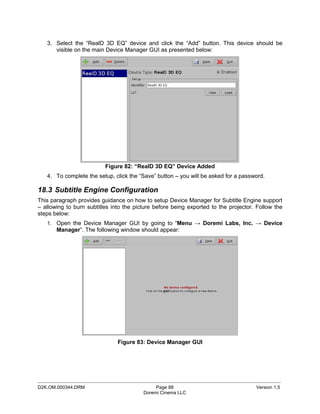
13.1.2 BIOS Setting for SuperMicro X7SBE Motherboard..................................................................67
13.2 SERVER LCD SCREEN MAINTENANCE.....................................................................................................68
13.2.1 “Root” Logging.........................................................................................................................68
13.2.2 Server LCD Screen Calibration...............................................................................................68
14 APPENDIX A: GENERAL PURPOSE OUTPUT CONNECTION DIAGRAM.......................................69
15 APPENDIX B: GENERAL PURPOSE INPUT CONNECTION DIAGRAM...........................................70
16 APPENDIX C: XML STRUCTURE USED BY MACRO EDITOR.........................................................71
16.1 AUTOMATIONCUEMACROLIST SAMPLE.....................................................................................................71
16.2 AUTOMATIONCUEMACROLIST STRUCTURE................................................................................................72
16.2.1 IssueDate Node.......................................................................................................................73
16.2.2 Issuer Node.............................................................................................................................73
16.2.3 Creator Node...........................................................................................................................73
16.2.4 AnnotationText Node...............................................................................................................73
16.2.5 AutomationCueMacro Nodes..................................................................................................73
16.2.6 Command Node [optional].......................................................................................................74
16.2.7 TriggerCue Node [optional].....................................................................................................77
16.3 SCHEMA...........................................................................................................................................79
16.4 XML DIAGRAM LEGEND.......................................................................................................................81
16.4.1 Element symbols.....................................................................................................................81
16.4.2 Model symbols ("compositors")...............................................................................................82
16.5 TYPES..............................................................................................................................................82
16.6 MODEL GROUPS AND REFERENCES..........................................................................................................83
17 ANNEX D: NETMAP CONFIGURATION FILE.....................................................................................84
17.1 OVERVIEW ........................................................................................................................................84
17.2 NETMAP FILE STRUCTURE....................................................................................................................84
17.3 SAMPLE NETMAP FILE.........................................................................................................................86
17.4 KNOWN ISSUES..................................................................................................................................86
18 ANNEX E: DEVICE MANAGER CONFIGURATION FOR LICENSED FEATURES............................87
18.1 DOLBY 3D CONFIGURATION..................................................................................................................87
18.2 REALD 3D CONFIGURATION.................................................................................................................87
18.3 SUBTITLE ENGINE CONFIGURATION..........................................................................................................88
19 ACRONYMS........................................................................................................................................91
20 DOCUMENT REVISION HISTORY......................................................................................................92
_____________________________________________________________________________________________
D2K.OM.000344.DRM Page 4 Version 1.5
Doremi Cinema LLC](https://image.slidesharecdn.com/dcp-2000fieldinstmanual000344v15-110315043125-phpapp02/85/Dcp-2000-field-instmanual_000344_v1_5-4-320.jpg)

![12.5.4 Performing the Firmware Upgrade
To perform the upgrade of the Dolphin firmware, simply reboot the DCP-2000.
To do this, login as 'root' and from a terminal command prompt, type: reboot <enter>.
After rebooting, you can check your firmware version from a terminal command prompt to verify
the new software/firmware versions by repeating Section 12.3.
12.6 Network Restarting
To restart networking from the terminal command line, do the following:
type: /etc/init.d/networking restart <enter>
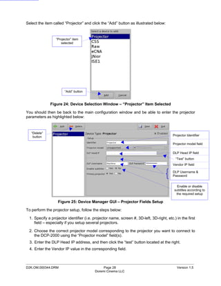
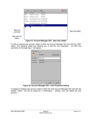
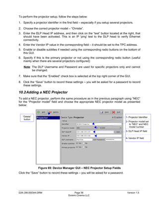
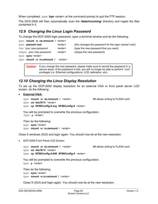
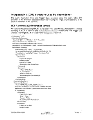
12.7 RAID
Two RAIDs are presents in the DCP-2000: “/dev/md0” which is mounted on “/data” and
‘/dev/md1” which is mounted on “/opt”. The following paragraphs explain how to check the
health of the RAID – see 12.7.1 – and how to reinit the RAID – see 12.7.2.
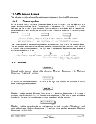
12.7.1 RAID Failure Identification
To check the health of the RAID, just open a terminal, switch to “root” if you are not, and then
execute the following command:
type: more /proc/mdstat <enter>
On a healthy RAID, this command will print for example:
Personalities : [raid5]
md1 : active raid5 sda1[0] sdb1[1] sdc1[2]
21125248 blocks level 5, 64k chunk, algorithm 2 [3/3] [UUU]
md0 : active raid5 sda2[0] sdb2[1] sdc2[2]
760291968 blocks level 5, 64k chunk, algorithm 2 [3/3] [UUU]
On a failed RAID, this command will print:
Personalities : [raid5]
md1 : active raid5 sdb1[1] sdc1[2]
21125248 blocks level 5, 64k chunk, algorithm 2 [3/2] [_UU]
md0 : active raid5 sdb2[1] sdc2[2]
760291968 blocks level 5, 64k chunk, algorithm 2 [3/2] [_UU]
In the failed example above, the hard disk drive “/dev/sda” is failed. This failure could be the
result of a hardware failure or it could simply be that the user inadvertently pulled the drive out.
_____________________________________________________________________________________________
D2K.OM.000344.DRM Page 63 Version 1.5
Doremi Cinema LLC](https://image.slidesharecdn.com/dcp-2000fieldinstmanual000344v15-110315043125-phpapp02/85/Dcp-2000-field-instmanual_000344_v1_5-63-320.jpg)
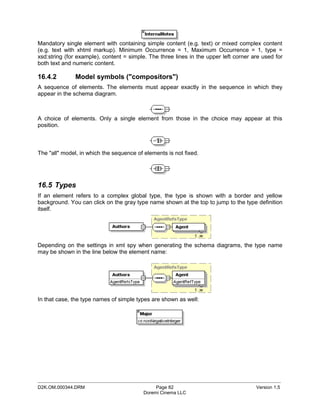
![13 Troubleshooting
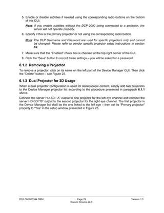
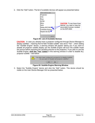
13.1 DCP-2000 BIOS Settings
In case the system does not complete the boot sequence upon powering up, the BIOS settings
may have to be checked. Follow the procedure below to confirm the BIOS settings.
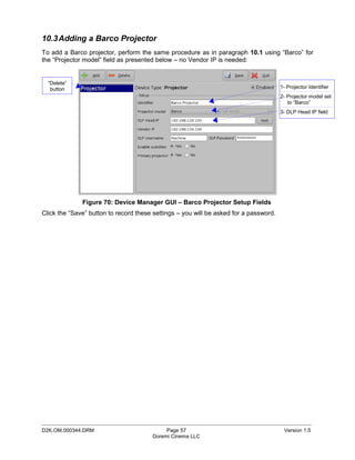
13.1.1 BIOS Setting for Intel SE7221 Motherboard
CAUTION: The BIOS settings detailed here are for unit fitted with the SE7221 motherboard
only – check the motherboard I/Os on the rear panel according to section 4.3.1.2 to
know which motherboard is used on the unit.
To access the BIOS settings of the DCP-2000, press F2 just after powering ON the unit.
This will bring up the System Setup screen in the Main menu. From here, set the system date
and time if necessary.
o Select the Advanced menu, enable AHCI mode, scroll down to IDE Configuration and
press <enter>. Verify that the drives are present on Primary IDE Master, Primary IDE
Slave, Secondary IDE Master, Third IDE Master.
o Go to Third IDE Master and press <enter>.
Verify that the Third IDE Master says:
Vendor PQI IDE DiskOnModule (This is the boot device for the DSV-J2. It is a
flash drive)
o Press ESC and select the Boot menu. Press <enter> and select the Hard Disk Drive.
The following info should appear – this is the boot drive order:
1st Drive [3M-PQI IDE Dis]
2nd Drive [PM-Hitachi HDT]
3rd Drive [PS-Hitachi HDT]
4th Drive [SM-Hitachi HDT]
o Press ESC and go to the Boot Device Priority. Set the flash drive to be the first boot
device.
o Select the Exit menu. Press <enter> for Exit Saving Changes. At the prompt, press
'OK' <enter>.
The DCP-2000 will now continue the boot process with the new BIOS settings.
_____________________________________________________________________________________________
D2K.OM.000344.DRM Page 66 Version 1.5
Doremi Cinema LLC](https://image.slidesharecdn.com/dcp-2000fieldinstmanual000344v15-110315043125-phpapp02/85/Dcp-2000-field-instmanual_000344_v1_5-66-320.jpg)
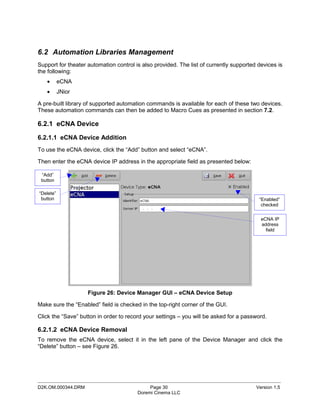
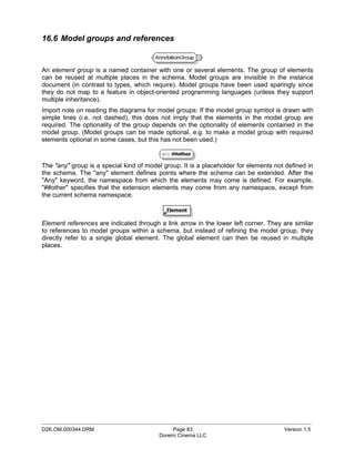
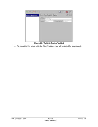
![13.1.2 BIOS Setting for SuperMicro X7SBE Motherboard
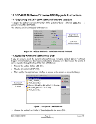
CAUTION: The BIOS settings detailed here are for unit fitted with the SuperMicro X7BE
motherboard only - check the motherboard I/Os on the rear panel according to
section 4.3.1.1 to know which motherboard is used on the unit.
To access the BIOS settings of the DCP-2000 fitted with the SuperMicro X7SBE motherboard,
press the “Delete” key just after powering ON the keyboard when the SuperMicro load (splash)
screen appears, in order to enter into the BIOS configuration.
1. In “Main” tab, the Time and Date should be set to “GMT” (Greenwich Mean Time) time
and date.
2. Check that the following is active:
Native Mode Operation [Serial ATA]
SATA RAID Enable [Disabled]
SATA AHCI Enable [Enabled]
SATA AHCI Legacy Enable [Disabled]
3. Go in “Advanced” menu, choose “Boot Features” and make sure that the following is set:
Only USB Port #6 cab boot [Enabled]
Power Loss Control [Last State]
4. Still within the “Advanced” menu, go to “Hardware Monitor” and make sure that the
following is set:
Fan Speed Control Mode [3-pin Server]
5. In the “Boot” menu:
Press the key “3” to load Doremi boot order. You should read:
Boot Priority Order:
1. USB HDD: xxxxName_of_the_Boot_Compact_Flashxxxxx
6. After Boot Priority is correctly set, press F10 and confirm by pressing <enter>.
The DCP-2000 will now continue the boot process with the new BIOS settings.
_____________________________________________________________________________________________
D2K.OM.000344.DRM Page 67 Version 1.5
Doremi Cinema LLC](https://image.slidesharecdn.com/dcp-2000fieldinstmanual000344v15-110315043125-phpapp02/85/Dcp-2000-field-instmanual_000344_v1_5-67-320.jpg)
![16.2.5.2 Id Node
The Id element uniquely identifies the AutomationCueMacro for asset management purposes.
It is encoded as a urn:uuid per [RFC 4122].
16.2.5.3 AnnotationText Node [optional]
This AnnotationText element is a human-readable annotation corresponding to the comment
assigned to this Macro Cue when it was created. It is the name chosen by the user in 7.2.1 for
the field “Comments”.
16.2.5.4 CommandList Node
The CommandList element contains a list of zero, one or more Command elements. Each
Command element corresponds to the set of parameters describing one automation individual
command composing the Macro Automation Cue.
An empty CommandList can be used to generate an Automation Cue Macro executing no
command. It will just be used to maintain portability between theaters.
16.2.6 Command Node [optional]
A Command node contains the parameters associated to a specific command to be used as part
of the overall AutomationCueMacro element. These parameters depend on the type of
command defined by the Type node below.
Figure 77: Command Structure.
Dotted lines denote optional elements that can be omitted during the creation based on Macro Editor.
_____________________________________________________________________________________________
D2K.OM.000344.DRM Page 74 Version 1.5
Doremi Cinema LLC](https://image.slidesharecdn.com/dcp-2000fieldinstmanual000344v15-110315043125-phpapp02/85/Dcp-2000-field-instmanual_000344_v1_5-74-320.jpg)
![16.2.6.1 Type Sub-Node
The available types of commands are listed below:
Table 1: Command Types Available
Type Description
Black Black video and silent audio signals will be generated by the server
GPO A GPO will be sent by the server
Dowser The command concerns the projector dowser
Lamp The command concerns the projector lamp
Channel The command concerns the projector channel
Play The command will put the server in play mode
Pause The command will put the server in pause mode
TogglePlayPause The command will put the server in TogglePlayPause mode
VideoOutputMode The command will set the video output mode
ProjectorMacro The command will specify a DLP projector macro
DeviceRawSendMessage The command will send a message to a device
PurgePendingMacro The command will purge pending macros
Note: In case the command type is Play, Pause, TogglePlayPause or PurgePendingMacro, no
additional parameters are required within the Command element.
16.2.6.2 Duration Sub-Node [optional]
The Duration element has only to be used for the “Black” command type. It specifies the
duration – as a number of seconds - of the associated black video and silent audio output.
16.2.6.3 Line Sub-Node [optional]
The Line element has only to be used for the “GPO” command type. It specifies the GPO line
number to be used for the associated command. It contains an integer to be chosen between 0
and 7.
16.2.6.4 Value Sub-Node [optional]
The Value element has only to be used for “GPO”, “Dowser”, “Lamp”, “Channel”,
“VideoOutputMode” and “ProjectorMacro” command types.
When used for the “GPO” command, it has to be the Value element grouped with the Line and
optional PulseDelay elements sequence. When used for the “Dowser”, “Lamp”, Channel”,
“VideoOutputMode” or “ProjectorMacro” commands, it has to be the standalone Value element
defined at the same level as the Duration element in the schema – see Figure 77.
The format of this Value element also depends on the kind of command type. The table below
presents the usage of such elements for each command type:
_____________________________________________________________________________________________
D2K.OM.000344.DRM Page 75 Version 1.5
Doremi Cinema LLC](https://image.slidesharecdn.com/dcp-2000fieldinstmanual000344v15-110315043125-phpapp02/85/Dcp-2000-field-instmanual_000344_v1_5-75-320.jpg)
![Table 2: Value Formats
Type Associated Value Format Description
GPO Possible values:
- 0: means GPO OFF
- 1: means GPO ON
- 2: means GPO Pulse mode
Dowser Possible values:
- 0: means Dowser OFF
- 1: means Dowser ON
Lamp Possible values:
- 0: means Lamp OFF
- 1: means Lamp ON
Channel The Value element is an integer chosen between 0 and 16. This integer
indicates to which projector channel to switch.
VideoOutputMode Possible values:
- DolphinlorConversionDefault: default video output mode
- DolphinColorConversion444to422: video output mode allowing
playback of the corresponding 24fps Package at 48fps.
ProjectorMacro The value indicates the concerned projector macro name
16.2.6.5 PulseDelay Sub-Node [optional]
The PulseDelay element has only to be present for the “GPO” command when the associated
value is set to 2 (Pulse Mode) – see Table 2 above. Its value is the duration, in milliseconds,
during which the associated GPO will remain ON level before going to OFF.
16.2.6.6 DeviceName Sub-Node [optional]
The DeviceName element has only to be present for the “DeviceRawSendMessage” command.
It will contain the name of the device to which the message has to be sent.
16.2.6.7 MessageType Sub-Node [optional]
The MessageType element has only to be present for the “DeviceRawSendMessage”
command. It will define the type of the message (e.g. text, binary).
16.2.6.8 Message Sub-Node [optional]
The Message element has only to be present for the “DeviceRawSendMessage” command. It
contains the actual message to be sent to the device.
_____________________________________________________________________________________________
D2K.OM.000344.DRM Page 76 Version 1.5
Doremi Cinema LLC](https://image.slidesharecdn.com/dcp-2000fieldinstmanual000344v15-110315043125-phpapp02/85/Dcp-2000-field-instmanual_000344_v1_5-76-320.jpg)
![16.2.7 TriggerCue Node [optional]
Each TriggerCue element corresponds to all the parameters defining a TriggerCue. These
parameters are recorded in the sub-nodes presented in the following paragraphs.
Figure 78: TriggerCue Structure.
Dotted lines denote optional elements that can be omitted during the creation based on Macro Editor.
Several TriggerCue elements can be generated. They just have to be put back to back at this
XML level (see Figure 75).
A TriggerCue node without CueType and CueParameter element can be used to generate a
Trigger Cue executing no command. It will just be used to maintain portability between theaters.
In such a case, the only required sub-elements are the Name and the Id element below.
16.2.7.1 Name Node
The Name element is a human-readable annotation corresponding to the name given to this
TriggerCue when it was created. It is the name chosen by the user in Figure 40 for the field
“Name of the Trigger”.
16.2.7.2 Id Node
The Id element uniquely identifies the TriggerCue for asset management purposes. It is
encoded as a urn:uuid per [RFC 4122].
16.2.7.3 AnnotationText Node [optional]
This AnnotationText element is a human-readable annotation corresponding to the comment
assigned to this TriggerCue when it was created. It is the name chosen by the user in Figure
40 for the field “Comments”.
_____________________________________________________________________________________________
D2K.OM.000344.DRM Page 77 Version 1.5
Doremi Cinema LLC](https://image.slidesharecdn.com/dcp-2000fieldinstmanual000344v15-110315043125-phpapp02/85/Dcp-2000-field-instmanual_000344_v1_5-77-320.jpg)
![16.2.7.4 CueType Node [optional]
The CueType element corresponds to the type of Cue used by the TriggerCue. The available
Cue Types are listed in the table below:
Table 3: Cue Types Available
Type Description
GPI Allows assignment of a GPI line and value to the Trigger
Signal Allows assignment of another signal to the Trigger
16.2.7.5 CueTypeParameters [optional]
The CueTypeParameters element contains the parameters associated to the Cue type
defined in the CueType element.
Figure 79: TriggerCue Structure.
Dotted lines denote optional elements that can be omitted during the creation based on the Macro Editor.
• For GPI Cue Type, the two following parameters have to be used: Line and Value.
The Line element specifies the GPI line number to be used for the associated command. It
contains an integer to be chosen between 0 and 7.
The Value element indicates the state of the GPI: ON (Value = 1) or OFF (Value = 2).
• For Signal Cue Type, the following parameter has to be used: Name.
The Name element specifies the signal name.
_____________________________________________________________________________________________
D2K.OM.000344.DRM Page 78 Version 1.5
Doremi Cinema LLC](https://image.slidesharecdn.com/dcp-2000fieldinstmanual000344v15-110315043125-phpapp02/85/Dcp-2000-field-instmanual_000344_v1_5-78-320.jpg)
![<!-- CueTypeParameters -->
<xs:complexType name="CueTypeParametersType">
<xs:choice>
<xs:sequence>
<xs:element name="Line" type="xs:long"/>
<xs:element name="Value" type="aml:UserText”/>
</xs:sequence>
<xs:element name="Name" type="aml:UserText"/>
</xs:choice>
</xs:complexType>
<!-- Command -->
<xs:complexType name="CommandType">
<xs:sequence>
<xs:element name="Type" type="aml:UserText"/>
<xs:choice minOccurs="0">
<xs:sequence>
<xs:element name="Line" type="xs:long"/>
<xs:element name="Value" type="aml:UserText"/>
<xs:element name="PulseDelay" type="aml:UserText" minOccurs="0"/>
</xs:sequence>
<xs:element name="Value" type="aml:UserText"/>
<xs:element name="Duration" type="xs:long"/>
<xs:sequence>
<xs:element name="DeviceName" type="aml:UserText"/>
<xs:element name="MessageType" type="aml:UserText"/>
<xs:element name="Message" type="aml:UserText"/>
</xs:sequence>
</xs:choice>
</xs:sequence>
</xs:complexType>
<!-- UUID -->
<xs:simpleType name="UUID">
<xs:restriction base="xs:anyURI">
<xs:pattern value="urn:uuid:[0-9a-fA-F]{8}-[0-9a-fA-F]{4}-[0-9a-fA-F]{4}-[0-9a-fA-F]{4}-
[0-9a-fA-F]{12}"/>
</xs:restriction>
</xs:simpleType>
<!-- UserText -->
<xs:complexType name="UserText">
<xs:simpleContent>
<xs:extension base="xs:string">
<xs:attribute name="language" type="xs:language" use="optional" default="en"/>
</xs:extension>
</xs:simpleContent>
</xs:complexType>
</xs:schema>
_____________________________________________________________________________________________
D2K.OM.000344.DRM Page 80 Version 1.5
Doremi Cinema LLC](https://image.slidesharecdn.com/dcp-2000fieldinstmanual000344v15-110315043125-phpapp02/85/Dcp-2000-field-instmanual_000344_v1_5-80-320.jpg)


![Erpi admin 11123510[1] by иссам неязын issam hejazin](https://cdn.slidesharecdn.com/ss_thumbnails/erpiadmin111235101-140814022227-phpapp01-thumbnail.jpg?width=640&height=640&fit=bounds)


![Hd dvr-1004[1]](https://cdn.slidesharecdn.com/ss_thumbnails/hd-dvr-10041-120121025501-phpapp01-thumbnail.jpg?width=640&height=640&fit=bounds)


![Cimco edit 5 user guide[1]](https://cdn.slidesharecdn.com/ss_thumbnails/cimcoedit5userguide1-110305112440-phpapp01-thumbnail.jpg?width=640&height=640&fit=bounds)


