MetaFabric™ Architecture Virtualized Data Center: Design and Implementation G...Juniper Networks
The benefits of virtualization are driving data center operators to rethink their legacy data center networks and look for new ways to reduce costs and improve efficiency in the data center. Moving from a legacy network to a state-of-the-art solution allows you to deploy new applications in seconds rather than days, weeks, or months. If you want to harness the power of virtualization in your data center network, this guide will help you to achieve your goal.
Builder.ai Founder Sachin Dev Duggal's Strategic Approach to Create an Innova...Ramesh Iyer
In today's fast-changing business world, Companies that adapt and embrace new ideas often need help to keep up with the competition. However, fostering a culture of innovation takes much work. It takes vision, leadership and willingness to take risks in the right proportion. Sachin Dev Duggal, co-founder of Builder.ai, has perfected the art of this balance, creating a company culture where creativity and growth are nurtured at each stage.
Encryption in Microsoft 365 - ExpertsLive Netherlands 2024Albert Hoitingh
In this session I delve into the encryption technology used in Microsoft 365 and Microsoft Purview. Including the concepts of Customer Key and Double Key Encryption.
GDG Cloud Southlake #33: Boule & Rebala: Effective AppSec in SDLC using Deplo...James Anderson
Effective Application Security in Software Delivery lifecycle using Deployment Firewall and DBOM
The modern software delivery process (or the CI/CD process) includes many tools, distributed teams, open-source code, and cloud platforms. Constant focus on speed to release software to market, along with the traditional slow and manual security checks has caused gaps in continuous security as an important piece in the software supply chain. Today organizations feel more susceptible to external and internal cyber threats due to the vast attack surface in their applications supply chain and the lack of end-to-end governance and risk management.
The software team must secure its software delivery process to avoid vulnerability and security breaches. This needs to be achieved with existing tool chains and without extensive rework of the delivery processes. This talk will present strategies and techniques for providing visibility into the true risk of the existing vulnerabilities, preventing the introduction of security issues in the software, resolving vulnerabilities in production environments quickly, and capturing the deployment bill of materials (DBOM).
Speakers:
Bob Boule
Robert Boule is a technology enthusiast with PASSION for technology and making things work along with a knack for helping others understand how things work. He comes with around 20 years of solution engineering experience in application security, software continuous delivery, and SaaS platforms. He is known for his dynamic presentations in CI/CD and application security integrated in software delivery lifecycle.
Gopinath Rebala
Gopinath Rebala is the CTO of OpsMx, where he has overall responsibility for the machine learning and data processing architectures for Secure Software Delivery. Gopi also has a strong connection with our customers, leading design and architecture for strategic implementations. Gopi is a frequent speaker and well-known leader in continuous delivery and integrating security into software delivery.
JMeter webinar - integration with InfluxDB and GrafanaRTTS
Watch this recorded webinar about real-time monitoring of application performance. See how to integrate Apache JMeter, the open-source leader in performance testing, with InfluxDB, the open-source time-series database, and Grafana, the open-source analytics and visualization application.
In this webinar, we will review the benefits of leveraging InfluxDB and Grafana when executing load tests and demonstrate how these tools are used to visualize performance metrics.
Length: 30 minutes
Session Overview
-------------------------------------------
During this webinar, we will cover the following topics while demonstrating the integrations of JMeter, InfluxDB and Grafana:
- What out-of-the-box solutions are available for real-time monitoring JMeter tests?
- What are the benefits of integrating InfluxDB and Grafana into the load testing stack?
- Which features are provided by Grafana?
- Demonstration of InfluxDB and Grafana using a practice web application
To view the webinar recording, go to:
https://www.rttsweb.com/jmeter-integration-webinar
Accelerate your Kubernetes clusters with Varnish CachingThijs Feryn
A presentation about the usage and availability of Varnish on Kubernetes. This talk explores the capabilities of Varnish caching and shows how to use the Varnish Helm chart to deploy it to Kubernetes.
This presentation was delivered at K8SUG Singapore. See https://feryn.eu/presentations/accelerate-your-kubernetes-clusters-with-varnish-caching-k8sug-singapore-28-2024 for more details.
LF Energy Webinar: Electrical Grid Modelling and Simulation Through PowSyBl -...DanBrown980551
Do you want to learn how to model and simulate an electrical network from scratch in under an hour?
Then welcome to this PowSyBl workshop, hosted by Rte, the French Transmission System Operator (TSO)!
During the webinar, you will discover the PowSyBl ecosystem as well as handle and study an electrical network through an interactive Python notebook.
PowSyBl is an open source project hosted by LF Energy, which offers a comprehensive set of features for electrical grid modelling and simulation. Among other advanced features, PowSyBl provides:
- A fully editable and extendable library for grid component modelling;
- Visualization tools to display your network;
- Grid simulation tools, such as power flows, security analyses (with or without remedial actions) and sensitivity analyses;
The framework is mostly written in Java, with a Python binding so that Python developers can access PowSyBl functionalities as well.
What you will learn during the webinar:
- For beginners: discover PowSyBl's functionalities through a quick general presentation and the notebook, without needing any expert coding skills;
- For advanced developers: master the skills to efficiently apply PowSyBl functionalities to your real-world scenarios.
Elevating Tactical DDD Patterns Through Object CalisthenicsDorra BARTAGUIZ
After immersing yourself in the blue book and its red counterpart, attending DDD-focused conferences, and applying tactical patterns, you're left with a crucial question: How do I ensure my design is effective? Tactical patterns within Domain-Driven Design (DDD) serve as guiding principles for creating clear and manageable domain models. However, achieving success with these patterns requires additional guidance. Interestingly, we've observed that a set of constraints initially designed for training purposes remarkably aligns with effective pattern implementation, offering a more ‘mechanical’ approach. Let's explore together how Object Calisthenics can elevate the design of your tactical DDD patterns, offering concrete help for those venturing into DDD for the first time!
Transcript: Selling digital books in 2024: Insights from industry leaders - T...BookNet Canada
The publishing industry has been selling digital audiobooks and ebooks for over a decade and has found its groove. What’s changed? What has stayed the same? Where do we go from here? Join a group of leading sales peers from across the industry for a conversation about the lessons learned since the popularization of digital books, best practices, digital book supply chain management, and more.
Link to video recording: https://bnctechforum.ca/sessions/selling-digital-books-in-2024-insights-from-industry-leaders/
Presented by BookNet Canada on May 28, 2024, with support from the Department of Canadian Heritage.
DevOps and Testing slides at DASA ConnectKari Kakkonen
My and Rik Marselis slides at 30.5.2024 DASA Connect conference. We discuss about what is testing, then what is agile testing and finally what is Testing in DevOps. Finally we had lovely workshop with the participants trying to find out different ways to think about quality and testing in different parts of the DevOps infinity loop.
Software Delivery At the Speed of AI: Inflectra Invests In AI-Powered QualityInflectra
In this insightful webinar, Inflectra explores how artificial intelligence (AI) is transforming software development and testing. Discover how AI-powered tools are revolutionizing every stage of the software development lifecycle (SDLC), from design and prototyping to testing, deployment, and monitoring.
Learn about:
• The Future of Testing: How AI is shifting testing towards verification, analysis, and higher-level skills, while reducing repetitive tasks.
• Test Automation: How AI-powered test case generation, optimization, and self-healing tests are making testing more efficient and effective.
• Visual Testing: Explore the emerging capabilities of AI in visual testing and how it's set to revolutionize UI verification.
• Inflectra's AI Solutions: See demonstrations of Inflectra's cutting-edge AI tools like the ChatGPT plugin and Azure Open AI platform, designed to streamline your testing process.
Whether you're a developer, tester, or QA professional, this webinar will give you valuable insights into how AI is shaping the future of software delivery.
Generating a custom Ruby SDK for your web service or Rails API using Smithyg2nightmarescribd
Have you ever wanted a Ruby client API to communicate with your web service? Smithy is a protocol-agnostic language for defining services and SDKs. Smithy Ruby is an implementation of Smithy that generates a Ruby SDK using a Smithy model. In this talk, we will explore Smithy and Smithy Ruby to learn how to generate custom feature-rich SDKs that can communicate with any web service, such as a Rails JSON API.
Slack (or Teams) Automation for Bonterra Impact Management (fka Social Soluti...Jeffrey Haguewood
Sidekick Solutions uses Bonterra Impact Management (fka Social Solutions Apricot) and automation solutions to integrate data for business workflows.
We believe integration and automation are essential to user experience and the promise of efficient work through technology. Automation is the critical ingredient to realizing that full vision. We develop integration products and services for Bonterra Case Management software to support the deployment of automations for a variety of use cases.
This video focuses on the notifications, alerts, and approval requests using Slack for Bonterra Impact Management. The solutions covered in this webinar can also be deployed for Microsoft Teams.
Interested in deploying notification automations for Bonterra Impact Management? Contact us at sales@sidekicksolutionsllc.com to discuss next steps.
4. 1
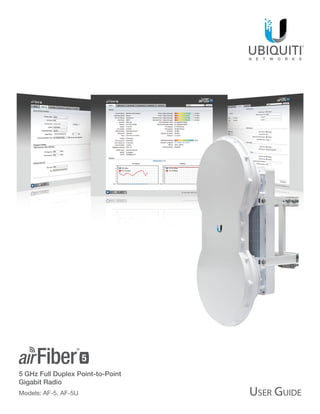
Chapter 1: OverviewairFiber®
AF5/AF5U User Guide
Ubiquiti Networks, Inc.
airFiber Configuration Interface
System Requirements
• Microsoft Windows Vista, Windows 7, Windows 8, Linux,
or Mac OS X
• Java Runtime Environment 1.6 (or above)
• Web Browser: Mozilla Firefox, Apple Safari, Google
Chrome, or Microsoft Internet Explorer 8 (or above)
Hardware Overview
Side
Grounding Point
Elevation Rod
Hex Nut
to adjust
Elevation Rod
Pre-Installed
M10 x25
Flanged Bolts
Lanyard Attachment
Loop
Lanyard Attachment
Loop
Assembled View
Chapter 1: Overview
Introduction
Thank you for purchasing the Ubiquiti Networks®
airFiber® 5 GHz Full Duplex Point-to-Point Gigabit Radio.
This User Guide is for use with the following models:
Model Description Operating Frequency*
AF-5 Supports mid-band frequencies 5470 - 5950 MHz
AF-5U Supports high-band frequencies 5725 - 6200 MHz
* Refer to “Specifications” on page 40 for more
information.
The mid-band model, AF-5, features the popular mid‑band
frequencies, which are freely used in many parts of
the world. The high-band model, AF-5U, which can
operate in the 5.7 - 6.2 GHz bands, has robust filtering to
enable co-location with devices operating in the lower 5
GHz bands while allowing operation at a higher output
power in many areas of the world.
The same instructions apply to both models, and the User
Guide will refer to both models as the airFiber AF-5.
Package Contents
airFiber
AF-5/AF-5U
I-Bracket Upper Mount Bracket
with Elevation Rod
Lower Mount
Bracket
Pole Clamps
(Qty. 2)
M10x150 Carriage Bolts
(Qty. 4)
M10x100 Carriage Bolts
(Qty. 2)
M8x14 Serrated Flange Bolts
(Qty. 4)
Azimuth Support Brackets
(Qty. 2)
M10 Serrated Flange Nuts
(Qty. 6)
Cable Ties
(Qty. 2)
GigE PoE Adapter
(50V, 1.2A)
Power Cord Quick Start Guide
TERMS OF USE: Ubiquiti radio devices must be professionally installed. Shielded Ethernet cable and
earth grounding must be used as conditions of product warranty. TOUGHCable™
is designed for
outdoor installations. It is the customer’s responsibility to follow local country regulations, including
operation within legal frequency channels, output power, and Dynamic Frequency Selection (DFS)
requirements.
5. 2
Chapter 1: OverviewairFiber®
AF5/AF5U User Guide
Ubiquiti Networks, Inc.
Interfaces
GPS
MASTER
LINK
RESET
OVERLOAD
8X
6X
4X TO 0.25X
REMOTE
LOCALMANAGEMENT DATAAUX
ACT SPEEDACT SPEED
Interface Description
Reset Button
To reset to factory defaults, press and hold the
Reset button for more than five seconds while
the unit is already powered on.
Remote Display
Displays the received signal strength in dBm of
the remote airFiber radio.
Local Display
Displays the received signal strength in dBm of
the local airFiber radio.
Management Port
10/100 Mbps, secured port for configuration.
By default, this is the only port that can
monitor, configure, and/or update firmware.
Aux Port Port for audio tone aiming.
Data Port 10/100/1000 Mbps port handles all user traffic.
LEDs
GPS
MASTER
LINK
RESET
OVERLOAD
8X
6X
4X to 0.25X
REMOTE
LOCAL AUXMANAGEMENT DATA
ACT SPEEDACT SPEED
LED State Status
GPS
Off No GPS Synchronization
On Operational (Strong Signal)
Normal Flash* Non-Operational (Weak Signal)
Master
Off Slave mode
On Master mode
Link Status
Off RF Off
Short Flash*
Syncing
DFS countries only:
• DFS CAC
• RADAR Detected
Normal Flash* Beaconing
Long Flash* Registering
On Operational
Remote On
Displays the received signal
strength in dBm of the remote
airFiber radio.
Local On
Displays the received signal
strength in dBm of the local
airFiber radio.
Overload Fast Flash
Overload Condition (Identify and
eliminate any source of strong
in‑band interference.)
(Unlabeled) On 10x (1024QAM MIMO)
8x On 256QAM MIMO
6x On 64QAM MIMO
4x to 0.25x
On 16QAM MIMO
Long Flash* QPSK MIMO
Normal Flash* 1x QPSK xRT™
**
Short Flash* ¼x QPSK xRT**
* Short Flash (1:3 on/off cycle)
Normal Flash (1:1 on/off cycle)
Long Flash (3:1 on/off cycle)
** xtreme Range Technology
Port LEDs
LED State Status
Management
Act
Off No Ethernet Link
On Ethernet Link Established
Random Flashing Ethernet Activity
Speed
Off 10 Mbps
On 100 Mbps
Data
Act
Off No Ethernet Link
On Ethernet Link Established
Random Flashing Ethernet Activity
Speed
Off 10/100 Mbps
On 1000 Mbps
6. 3
Chapter 2: InstallationairFiber®
AF5/AF5U User Guide
Ubiquiti Networks, Inc.
Chapter 2: Installation
Link Planning
Before you install the airFiber AF-5, consider the following:
• Point-to-Point (PtP), daisy chain, or ring configuration
• Co-Location
Configuration
There are three typical configurations:
• PtP backhaul Uses two airFiber radios, one configured
as Master and the other configured as Slave.
SlaveMaster
Point-to-Point Backhaul
• Daisy chain Uses multiple airFiber radios to extend
the distance of a link, like a relay from point to point to
point. The airFiber radios in the same node must use the
same Wireless Mode (Master or Slave).
Daisy Chain Configuration
• Ring Uses multiple airFiber radios to form redundant
paths. If one link goes down, the other links have an
alternate route available. For each link, configure one
airFiber radio as Master, and configure the other as Slave.
Ring Configuration
Co-Location
You can co-locate multiple airFiber radios if they are
pointed in different directions. Co-located airFiber radios
must use the same Wireless Mode (Master or Slave).
Back‑to-back airFiber radios can use the same frequency.
We recommend that you use different frequencies for
adjacent airFiber radios; however, this is not a strict
requirement.
Installation Requirements
Pre-Assembly Tool
• 13 mm (½") wrench
Pole-Mounting Tool
• 17 mm (11/16") wrench
Other Requirements
• Clear line of sight between airFiber radios
• Clear view of the sky for proper GPS operation
• Vertical mounting orientation
• Mounting location with < 0.5° displacement due to twist
and sway under wind loading
• Mounting point:
• At least 1 m (3.28 ft) below the highest point on the
structure
• For tower installations, at least 3 m (9.84 ft) below the
top of the tower
• Ground wires – min. 10 AWG (5 mm2
) and max. length:
1 m (3.28 ft). As a safety precaution, ground the airFiber
radios to grounded masts, poles, towers, or grounding
bars.
WARNING: Failure to properly ground your
airFiber units will void your warranty.
• (Recommended) 2 Outdoor GigE PoE surge protectors
Note: For guidelines about grounding and
lightning protection, follow your local electrical
regulatory codes.
• Outdoor, shielded Category 6 (or above) cabling and
shielded RJ-45 connectors are required for all wired
Ethernet connections.
7. 4
Chapter 2: InstallationairFiber®
AF5/AF5U User Guide
Ubiquiti Networks, Inc.
Installation Overview
We recommend that you configure your paired airFiber
radios before mounting. Below is an overview of
the installation with specific details in the following
instructions:
• Connect Power over Ethernet to the Data port, and
connect an Ethernet cable between your computer and
the Management port.
• Configure the device settings in the airFiber
Configuration Interface.
• Once configuration is complete, disconnect the cables
to move the airFiber radios.
• Pre-assemble the mounting hardware.
• Install the airFiber radios at the site.
• Establish and optimize the RF link.
Note: The AF-5 and AF-5U models share the same
installation and configuration instructions.
Connecting Power over Ethernet
1. Push the button and slide the port cover down
to access cable ports. (The port cover cannot be
completely removed.)
2. Connect an Ethernet cable to the Data port.
GPS
MASTER
LINK
RESET
OVERLOAD
8X
6X
4X to 0.25X
REMOTE
LOCAL AUXMANAGEMENT DATA
ACT SPEEDACT SPEED
3. Connect the other end of the Ethernet cable from the
Data port to the Ethernet port labeled POE on the GigE
PoE Adapter.
4. Connect the Power Cord to the power port on the GigE
PoE Adapter. Connect the other end of the Power Cord
to a power source.
8. 5
Chapter 2: InstallationairFiber®
AF5/AF5U User Guide
Ubiquiti Networks, Inc.
airFiber Configuration
The instructions in this section explain how to access
the airFiber Configuration Interface and configure the
following settings:
• Wireless Mode Configure one airFiber radio as the
Master and the other as the Slave.
• Duplex The airFiber radio supports both half-duplex
and full‑duplex operation. Half-duplex operation
provides more frequency planning options at the
cost of higher latency and throughput. Full-duplex
operation provides the highest throughput and
lowest latency; however, you have fewer frequency
management options.
-- Half Duplex (default) The TX and RX Frequencies can
be the same or different to suit local interference.
TX
RX
TX
RX
SlaveMaster
Frequency A Frequency A
Half-Duplex Diagram
-- Full Duplex The TX and RX Frequencies should be
different.
TX
RX
TX
RX
SlaveMaster
Frequency A Frequency B
Full-Duplex Diagram
• TX and RX Frequencies The TX Frequency on the
Master must match the RX Frequency on the Slave, and
vice versa.
1. Connect an Ethernet cable from your computer to the
Management port on the airFiber radio.
GPS
MASTER
LINK
RESET
OVERLOAD
8X
6X
4X to 0.25X
REMOTE
LOCAL AUXMANAGEMENT DATA
ACT SPEEDACT SPEED
2. Configure the Ethernet adapter on your computer with
a static IP address on the 192.168.1.x subnet.
3. Launch your web browser. Type http://192.168.1.20 in
the address field and press enter (PC) or return (Mac).
4. The login screen will appear. Enter ubnt in the
Username and Password fields. Select your Country and
Language. You must agree to the Terms of Use to use
the product. Click Login.
Note: U.S. product versions are locked to the U.S.
Country Code to ensure compliance with FCC
regulations.
5. The Main tab will appear. Click the Tools drop-down
and select Link Calculator. This tool will guide you
on how to best minimize bandwidth and power/
interference issues.
Note: If you do not see the Link Calculator, then
upgrade the firmware on your airFiber radios.
Download the firmware at:
downloads.ubnt.com/airfiber
6. Enter the requirements of your link, and then click
Calculate. Adjust the values as needed to get the
optimal result, and then write down the settings
needed for your configuration.
9. 6
Chapter 2: InstallationairFiber®
AF5/AF5U User Guide
Ubiquiti Networks, Inc.
7. Click the Wireless tab.
8. Enter the Basic Wireless Settings:
a. For one airFiber radio, select Master from the Wireless
Mode drop-down. For the other airFiber radio, keep the
default, Slave.
b. Enter a name in the Link Name field. This should be the
same on both the Master and the Slave.
c. For the Duplex drop-down:
-- Half Duplex The default mode. The TX and RX
Frequencies can be the same or different to suit local
interference.
-- Full Duplex The TX and RX Frequencies should be
different.
d. Select a TX Frequency. This must match the RX
Frequency on your other airFiber radio.
e. Select a RX Frequency. This must match the TX
Frequency of your other airFiber radio.
f. If needed, change the Output Power and/or Maximum
Modulation Rate settings.
9. Configure the Wireless Security:
a. Select the AES Key Type, HEX or ASCII.
b. For the Key field:
-- HEX Enter 16 bytes (eight, 16-bit HEX values: 0-9, A-F,
or a-f). You can omit zeroes and use colons, similar to
the
IPv6 format.
Note: The airFiber Configuration Interface
supports IPv6 formats excluding dotted quad and
“::” (double‑colon) notation.
-- ASCII Enter a combination of alphanumeric
characters (0-9, A-Z, or a-z).
10. Click Change and then click Apply.
11. In-Band Management is enabled by default, so each
airFiber radio must have a unique IP Address. (If the
airFiber radios use the same IP Address, then you may
lose access to the airFiber radios via the Data ports.)
Click the Network tab.
a. For the Management IP Address option:
-- DHCP Keep the default, DHCP, to use DHCP
reservation on your router to assign a unique IP
Address.
-- Static Change the IP Address, Netmask, and other
settings to make them compatible with your network.
b. Click Change and then click Apply.
Repeat the instructions in the airFiber Configuration
section on your other airFiber radio. After you have
configured the airFiber radios, disconnect them and move
them to your installation site.
10. 7
Chapter 2: InstallationairFiber®
AF5/AF5U User Guide
Ubiquiti Networks, Inc.
Hardware Installation
The mounting hardware of the airFiber radio can be
pre‑assembled before pole-mounting.
Mounting Hardware Pre-Assembly
1. Insert two M10x150 Carriage Bolts into the Lower Mount
Bracket.
2. Insert two M10x150 Carriage Bolts into the Upper Mount
Bracket with Elevation Rod.
3. Attach the Lower Mount Bracket to the I-Bracket using
two M8x14 Serrated Flange Bolts. Ensure that the slots
face up and securely tighten the bolts.
Proper slot orientation
4. Attach the Upper Mount Bracket with Elevation Rod to
the I-Bracket using two M8x14 Serrated Flange Bolts.
Note: Ensure that the orientation of the Upper
Mount Bracket matches the illustration below, with
the Elevation Rod on the correct side.
11. 8
Chapter 2: InstallationairFiber®
AF5/AF5U User Guide
Ubiquiti Networks, Inc.
5. Attach the Pole Clamps to the Mount Brackets.
a. Slide the slotted hole of each Pole Clamp over one
upper and one lower M10x150 Carriage Bolt.
b. Place one M10 Serrated Flange Nut on each M10x150
Carriage Bolt.
6. Attach the Azimuth Support Brackets together.
a. Insert the two M10x100 Carriage Bolts into the Azimuth
Support Bracket that has two slotted holes.
b. Slide the slotted hole of the other Azimuth Support
Bracket over one M10x100 Carriage Bolt.
c. Place one M10 Serrated Flange Nut on each M10x100
Carriage Bolt.
7. Ensure that there is a 13 mm gap between the head
of each Pre-Installed M10x25 Flanged Bolt and the
corresponding trunnion on the airFiber radio.
13 mm13 mm
Pole-Mounting
1. Attach the Azimuth Support Brackets to the pole just
beneath the area where the airFiber radio will be
attached.
Note: The mounting assembly can accommodate a
Ø 38.1 - 101.6 mm (1.5" - 4.0") pole.
a. Orient the Azimuth Support Brackets around the pole so
it is aimed in the direction of the other airFiber radio.
b. Slide the open slot of the Azimuth Support Bracket over
the corresponding M10x100 Carriage Bolt.
c. Tighten the M10 Serrated Flange Nuts to approximately
50 N-m.
12. 9
Chapter 2: InstallationairFiber®
AF5/AF5U User Guide
Ubiquiti Networks, Inc.
2. Attach the mounting assembly to a pole.
a. Orient the mounting assembly around the pole so it is
aimed in the direction of the other airFiber radio.
b. Slide the open slot of each Pole Clamp over the
corresponding M10x150 Carriage Bolt.
c. Tighten the M10 Serrated Flange Nuts of the M10x150
Carriage Bolts to secure the mounting assembly to the
pole.
3. Lift the airFiber radio and align the two lower
Pre‑Installed M10x25 Flanged Bolts with the slots on the
Lower Mount Bracket. Seat the bolts in the slots.
13. 10
Chapter 2: InstallationairFiber®
AF5/AF5U User Guide
Ubiquiti Networks, Inc.
4. Align the two upper Pre-Installed M10x25 Flanged Bolts
of the airFiber radio next to the slots on the Upper
Mount Bracket. Lift the airFiber radio and seat the bolts
in the slots.
Grounding
To attach a ground wire:
1. Remove the nut from the Grounding Point.
2. Attach a ground wire (min. 8 AWG or 10 mm2
) to the
lug and replace the nut to secure the wire.
3. Secure the other end of the ground wire to a grounded
mast, pole, tower, or grounding bar.
WARNING: Failure to properly ground your
airFiber units will void your warranty.
Note: The ground wire should be as short as
possible and no longer than one meter in length.
Connecting Ethernet
1. Push the button and slide the port cover down
to access cable ports. (The port cover cannot be
completely removed.)
2. Connect the Data/PoE Ethernet cable:
a. Feed an outdoor, shielded CAT6 cable up through the
rightmost cable feed slot on the bottom of the port
cover.
b. Connect the cable to the Data port.
c. Create a strain relief for the Ethernet cable by feeding a
Cable Tie through the tie slot to the side of the cable.
d. Wrap the Cable Tie around the cable and tighten.
GPS
MASTER
LINK
RESET
OVERLOAD
8X
6X
4X to 0.25X
REMOTE
LOCALMANAGEMENT DATAAUX
ACT SPEEDACT SPEED
14. 11
Chapter 2: InstallationairFiber®
AF5/AF5U User Guide
Ubiquiti Networks, Inc.
3. Connect the other end of the Ethernet cable from the
Data port to the Ethernet port labeled POE on the GigE
PoE Adapter.
4. Connect an Ethernet cable from your network to the
Ethernet port labeled LAN on the GigE PoE Adapter.
5. Connect the Power Cord to the power port on the GigE
PoE Adapter. Connect the other end of the Power Cord
to a power source.
Note: For added protection, we recommend
installing two GigE PoE surge protectors. Install
the first surge protector within one meter of the
airFiber Data port, and install the second surge
protector at the ingress point of the location
housing the wired network equipment.
Below is a diagram of a finished installation with
recommended surge protectors installed.
Ground to Pole, Tower,
or Grounding Block:
Max. 1 m from
Ground Bonding Point
Max.1m
GigE PoE Adapter
Power Source
Outdoor GigE PoE
Surge Protector
Outdoor GigE PoE
Surge Protector
15. 12
Chapter 2: InstallationairFiber®
AF5/AF5U User Guide
Ubiquiti Networks, Inc.
Alignment
Tips
• To accurately align the airFiber radios for best
performance, you MUST align only one end of the link at
a time.
• For more convenient alignment, you may consider using
long‑range scopes (not included) temporarily attached
to your airFiber radios.
• You may need to use additional hardware to
compensate for issues such as the improper orientation
of a mounting pole or significant elevation differences
between airFiber radios.
Determining the Received Signal Level
There are three methods for determining the received
signal level:
• LED Displays (See the next column.)
• airFiber Configuration Interface (See “Using the
airFiber Configuration Interface” on page 14.)
• Audio tone (Optional equipment required. See “Using
the Audio Tone” on page 16.)
Using the LED Displays
Before a link is established, the Master’s LED Display looks
like this:
• GPS and Master LEDs are solidly lit
Note: The GPS LED may not be lit if there is a
weak GPS signal. A GPS signal is not required for
alignment.
• Link Status LED flashes (Normal Flash 1:1)
• Remote and Local LED Displays show a double dash
GPS
MASTER
LINK
RESET
OVERLOAD
8X
6X
4X to 0.25X
REMOTE
LOCAL AUXMANAGEMENT DATA
ACT SPEEDACT SPEED
Note: The Local LED Display may briefly flash a
large number (such as 95) when there is no link.
Establishing a Link
Adjust the positions of the Master and the Slave to
establish a link.
Note: The Master must be aimed first at the Slave
because the Slave does not transmit any RF signal
until it detects transmissions from the Master.
1. Ensure that the following bolts and nuts are loose:
• Four Pre-Installed M10x25 Flanged Bolts on the
airFiber radio (two on each side)
• Four M10 Hex Nuts used to lock the elevation
alignment on the Upper Mount Bracket (two on
each side)
16. 13
Chapter 2: InstallationairFiber®
AF5/AF5U User Guide
Ubiquiti Networks, Inc.
2. Ensure that the pole mount is snug yet the four M10
Hex Nuts attaching the Pole Clamps are loose enough to
allow rotation around the pole for azimuth alignment.
3. Master Visually aim the Master at the Slave. To adjust
the Master’s position:
a. Rotate the airFiber radio on the pole to align the
azimuth.
b. Use the hex nut on the Elevation Rod to adjust the
elevation.
Note: Do NOT make simultaneous adjustments on
the Master and Slave.
4. Slave Visually aim the Slave at the Master. To adjust the
Slave’s position:
a. Rotate the airFiber radio on the pole to align the
azimuth.
b. Use the hex nut on the Elevation Rod to adjust the
elevation.
5. Check to see if a link is established. Ensure that the Link
Status LED is solidly lit green and the Remote and Local
LED Displays of the Slave are displaying signal levels.
GPS
MASTER
LINK
RESET
OVERLOAD
6X
8X
4X to 0.25X
REMOTE
LOCAL AUXMANAGEMENT DATA
ACT SPEEDACT SPEED
6. Slave Aim the Slave at the Master to achieve the
strongest signal level on the Remote LED Display of the
Slave.
Note: Values on the LED Displays are displayed in
negative (-) dBm. For example, 67 represents a
received signal level of -67 dBm. Smaller numerical
values indicate stronger received signal levels. For
example, a reading of 49 is stronger than a reading
of 55.
Note: Maximum signal strength can best be
achieved by iteratively sweeping through both
azimuth and elevation.
7. Master Aim the Master at the Slave to achieve the
strongest signal level on the Remote LED Display of the
Master.
Note: If the Overload LED lights up, identify
and eliminate any source of strong in‑band
interference.
8. Repeat steps 6 and 7 until you achieve a symmetric
link, with the signal levels within 1 dB of each other.
This ensures the best possible data rate between the
airFiber radios.
GPS
MASTER
LINK
RESET
4X to 0.25X
OVERLOAD
8X
6X
REMOTE
LOCAL AUXMANAGEMENT DATA
ACT SPEEDACT SPEED
9. Lock the alignment on both airFiber radios by
tightening the nuts and bolts.
10. Observe the Local and Remote LED Displays of each
airFiber radio to ensure that the values remains
constant while tightening the nuts and bolts. If any LED
value changes during the locking process, loosen the
nuts and bolts, finalize the alignment of each airFiber
radio again, and retighten the nuts and bolts.
11. For each airFiber radio, close the port cover and ensure
that the Ethernet cable stays in the cable feed slot.
17. 14
Chapter 2: InstallationairFiber®
AF5/AF5U User Guide
Ubiquiti Networks, Inc.
Using the airFiber Configuration Interface
Before You Begin
Note: The instructions in this section assume that
you are viewing the Antenna Alignment screen of
the Master; however, you can also use the Antenna
Alignment screen of the Slave.
To access the airFiber Configuration Interface:
1. Make sure that your computer is connected to the
Management port on the airFiber AF-5.
2. Configure the Ethernet adapter on your computer with
a static IP address on the 192.168.1.x subnet.
3. Launch your web browser. Type http://192.168.1.20 in
the address field and press enter (PC) or return (Mac).
4. The login screen will appear. Enter ubnt in the
Username and Password fields. Click Login.
5. The Main tab of the airFiber Configuration Interface
appears. Click the Tools drop-down list at the top right
corner of the page.
6. Click Align Antenna. You will use the Align Antenna
tool to point and optimize the antenna in the direction
of maximum link signal. (The Antenna Alignment
window is designed to refresh every 250 milliseconds.
See “Align Antenna” on page 38 for more details.)
7. The Antenna Alignment window appears, displaying
the Signal Strengths for both airFiber radios. The Chain
Signal Strength bar graphs display the Signal Strengths
for the local airFiber AF-5 you have accessed, while the
Remote Signal Strength bar graphs display the Signal
Strengths for the remote airFiber AF-5.
Establishing a Link
Adjust the positions of the Master and the Slave to
establish a link.
Note: The Master must be aimed first at the Slave
because the Slave does not transmit any RF signal
until it detects transmissions from the Master.
1. Ensure that the following bolts and nuts are loose:
• Four Pre-Installed M10x25 Flanged Bolts on the
airFiber radio (two on each side)
• Four M10 Hex Nuts used to lock the elevation
alignment on the Upper Mount Bracket (two on
each side)
2. Ensure that the pole mount is snug yet the four M10
Hex Nuts attaching the Pole Clamps are loose enough to
allow rotation around the pole for azimuth alignment.
18. 15
Chapter 2: InstallationairFiber®
AF5/AF5U User Guide
Ubiquiti Networks, Inc.
3. Master Visually aim the Master at the Slave. To adjust
the Master’s position:
a. Rotate the airFiber radio on the pole to align the
azimuth.
b. Use the hex nut on the Elevation Rod to adjust the
elevation.
Note: Do NOT make simultaneous adjustments on
the Master and Slave.
4. Slave Visually aim the Slave at the Master. To adjust the
Slave’s position:
a. Rotate the airFiber radio on the pole to align the
azimuth.
b. Use the hex nut on the Elevation Rod to adjust the
elevation.
5. Check to see if a link is established. Ensure that the
local and Remote Signal Strength bar graphs are
displaying signal levels.
6. Slave Aim the Slave at the Master to achieve the
strongest signal level on the Remote Signal Strength bar
graph of the Slave.
Note: The Signal Strength bar graphs display the
absolute power level (in dBm) of the received
signal for each chain. Smaller numerical values
indicate stronger received signal levels. For
example, a reading of -49 dBm is stronger than a
reading of -55 dBm.
Note: Maximum signal strength can best be
achieved by iteratively sweeping through both
azimuth and elevation.
7. Master Aim the Master at the Slave to achieve the
strongest signal level on the local Signal Strength bar
graph of the Master.
Note: If the Overload LED lights up, identify
and eliminate any source of strong in‑band
interference.
8. Repeat steps 6 and 7 until you achieve a symmetric
link, with the signal levels within 1 dB of each other.
This ensures the best possible data rate between the
airFiber radios.
9. Lock the alignment on both airFiber radios by
tightening the nuts and bolts.
10. Observe the Antenna Alignment window to ensure
that the values remains constant while tightening
the nuts and bolts. If the values change during the
locking process, loosen the nuts and bolts, finalize the
alignment of each airFiber radio again, and retighten
the nuts and bolts.
11. For each airFiber radio, close the port cover and ensure
that the Ethernet cable stays in the cable feed slot.
19. 16
Chapter 2: InstallationairFiber®
AF5/AF5U User Guide
Ubiquiti Networks, Inc.
Using the Audio Tone
Before You Begin
Create your own cable adapter to connect the Aux port
to your headphones or other listening device. The cable
adapter requires two items:
• An RJ-12 cable with an RJ-12 connector
• A cable with a 3.5 mm, female, stereo phono jack (mono
jack is acceptable)
1. Attach the wire from pin 6 of the RJ-12 cable to the
return or shield wire of the 3.5 mm jack.
2. Attach the wire from pin 5 of the RJ-12 cable to both
the left and right channel wires of the 3.5 mm stereo
phono jack.
Note: For a mono jack, connect the wire from pin 5
to the + wire of the mono jack.
RJ-12 Connector
Return/Shield Left/Right
Channel
Wire to Pin 6
Wire to Pin 5
Pin
Audio Jack
6
5
4
3
2
1
Pinouts from RJ-12 to 3.5 mm Stereo Phono Jack
Note: Wire colors may vary on RJ-12 cables.
Establishing a Link
Adjust the positions of the Master and the Slave to
establish a link.
Note: The Master must be aimed first at the Slave
because the Slave does not transmit any RF signal
until it detects transmissions from the Master.
1. Ensure that the following bolts and nuts are loose:
• Four Pre-Installed M10x25 Flanged Bolts on the
airFiber radio (two on each side)
• Four M10 Hex Nuts used to lock the elevation
alignment on the Upper Mount Bracket (two on
each side)
2. Ensure that the pole mount is snug yet the four M10
Hex Nuts attaching the Pole Clamps are loose enough to
allow rotation around the pole for azimuth alignment.
20. 17
Chapter 2: InstallationairFiber®
AF5/AF5U User Guide
Ubiquiti Networks, Inc.
3. Master Visually aim the Master at the Slave. To adjust
the Master’s position:
a. Rotate the airFiber radio on the pole to align the
azimuth.
b. Use the hex nut on the Elevation Rod to adjust the
elevation.
Note: Do NOT make simultaneous adjustments on
the Master and Slave.
4. Slave Visually aim the Slave at the Master. To adjust the
Slave’s position:
a. Rotate the airFiber radio on the pole to align the
azimuth.
b. Use the hex nut on the Elevation Rod to adjust the
elevation.
5. Slave Listen to the audio tone of the Slave – the higher
the pitch, the stronger the signal strength. Aim the
Slave at the Master to achieve the strongest signal level
on the Slave.
Note: Maximum signal strength can best be
achieved by iteratively sweeping through both
azimuth and elevation.
6. Master Aim the Master at the Slave to achieve the
strongest signal level on the Master.
Note: If the Overload LED lights up, identify
and eliminate any source of strong in‑band
interference.
7. Repeat steps 6 and 7 until you achieve a symmetric
link, with the signal levels within 1 dB of each other.
This ensures the best possible data rate between the
airFiber radios.
Note: If you have difficulty discerning whether the
link is symmetric, you can use one of the following
methods to determine more precise, received
signal level readings.
• LED Display (See “Using the LED Displays” on
page 12.)
• airFiber Configuration Interface (See “Using
the airFiber Configuration Interface” on page
14.)
8. Lock the alignment on both airFiber radios by
tightening the nuts and bolts.
9. Listen to the audio tone for each airFiber radio
to ensure that the values remains constant while
tightening the nuts and bolts. If the audio tones
change during the locking process, loosen the nuts
and bolts, finalize the alignment of each airFiber radio
again, and retighten the nuts and bolts.
10. For each airFiber radio, close the port cover and ensure
that the Ethernet cable stays in the cable feed slot.
21. 18
Chapter 3: NavigationairFiber®
AF5/AF5U User Guide
Ubiquiti Networks, Inc.
Chapter 3: Navigation
The airFiber Configuration Interface is an advanced
operating system capable of powerful wireless and
routing features, built upon a simple and intuitive user
interface foundation.
The airFiber AF-5 uses the airFiber Configuration Interface
for easy configuration and management via a web
browser.
There are two ways to access the airFiber Configuration
Interface:
• Management Port Enabled by default. Use a direct
connection to the Management port for out-of-band
management.
• In-Band Management Enabled by default. In-band
management is available through the local Data port
or the Data port at the other end of the link. You can
disable it on the Network tab. (See “Management
Network Settings” on page 26 for more details.)
Accessing the airFiber Configuration
Interface
Connect to the airFiber Configuration Interface.
1. Make sure that your host machine is connected to the
LAN that is connected to the Management port on the
airFiber AF-5.
2. Configure the Ethernet adapter on your host system
with a static IP address on the 192.168.1.x subnet (for
example, 192.168.1.100).
3. Launch your web browser. Type http://192.168.1.20 in
the address field and press enter (PC) or return (Mac).
4. Upon initial login, the Terms of Use appear on the login
screen. Enter ubnt in the Username and Password fields,
and select the appropriate choices from the Country
and Language drop-down lists. Check the box next to
I agree to these terms of use, and click Login.
Note: U.S. product versions are locked to the U.S.
Country Code to ensure compliance with FCC
regulations.
5. The airFiber Configuration Interface will appear,
allowing you to customize your settings as needed.
22. 19
Chapter 3: NavigationairFiber®
AF5/AF5U User Guide
Ubiquiti Networks, Inc.
Product Verification
The airFiber Configuration Interface will verify whether a
product is genuine or counterfeit.
For a genuine airFiber AF-5, the airFiber Configuration
Interface will display a Genuine Product logo in the lower
left corner of the screen.
For any product that is not an official Ubiquiti product, the
airFiber Configuration Interface will display a counterfeit
warning. Please contact Ubiquiti at support@ubnt.com
regarding this product.
Note: For product models introduced prior to 2012,
the airFiber Configuration Interface will NOT display
any logo in the lower left corner of the screen.
Interface Tabs
The airFiber Configuration Interface contains six main
tabs, each of which provides a web-based management
page to configure a specific aspect of the airFiber AF-5.
This User Guide covers each tab with a chapter. For details
on a specific tab, refer to the appropriate chapter.
• Main The “Main Tab” on page 20 displays device
status, statistics, and network monitoring links.
• Wireless The “Wireless Tab” on page 23 configures
basic wireless settings, including the wireless mode, link
name, frequency, output power, speed, and wireless
security.
• Network The “Network Tab” on page 26 configures
the management network settings, Internet Protocol (IP)
settings, management VLAN, and automatic IP aliasing.
• Advanced The “Advanced Tab” on page 28
provides more precise wireless interface controls,
including advanced wireless settings and advanced
Ethernet settings.
• Services The “Services Tab” on page 31 configures
system management services: Ping Watchdog, Simple
Network Management Protocol (SNMP), servers (web,
SSH, telnet), Network Time Protocol (NTP) client,
Dynamic Domain Name System (DDNS) client, system
log, and device discovery.
• System The “System Tab” on page 35 controls
system maintenance routines, administrator account
management, location management, device
customization, firmware update, and configuration
backup. You can also change the language of the web
management interface.
Each page also contains network administration and
monitoring tools:
• “Align Antenna” on page 38
• “Discovery” on page 39
• “Ping” on page 39
• “Traceroute” on page 39
23. 20
Chapter 4: Main TabairFiber®
AF5/AF5U User Guide
Ubiquiti Networks, Inc.
Chapter 4: Main Tab
The Main tab displays a summary of the link status
information, current values of the basic configuration
settings, network settings and information, and traffic
statistics.
Status
Device Name Displays the customizable name or
identifier of the device. The Device Name (also known
as host name) is displayed in registration screens and
discovery tools.
Operating Mode Displays the mode of the airFiber AF-5:
Slave, Master, or Reset.
RF Link Status Displays the status of the airFiber AF-5:
RF Off, Syncing, Beaconing, Registering, Enabling, Listening,
Operational, DFS CAC, or RADAR Detected.
Note: Most of the RF Link Statuses map to specific
flash rates of the Link Status LED (See “LEDs” on
page 2 for more details.)
Status Flash Rate of LED
RF Off Off
Syncing
DFS countries only:
• DFS CAC
• RADAR Detected
Short Flash (1:3 on/off cycle)
Beaconing Normal Flash (1:1 on/off cycle)
Registering Long Flash (3:1 on/off cycle)
Operational On
24. 21
Chapter 4: Main TabairFiber®
AF5/AF5U User Guide
Ubiquiti Networks, Inc.
When the airFiber AF-5 operates in a DFS country, it
performs a Channel Availability Check (CAC) before
operating. The rules vary by country and frequency, but in
general:
• FCC domains If the airFiber AF-5 operates in the DFS
band (5.4 GHz band), then the following rule applies:
• If the TX and RX Frequencies are the same, then the
airFiber AF-5 performs a 60-second check on the
Master only.
• If the TX and RX Frequencies are different, then the
airFiber AF-5 performs a 60-second check on both the
Master and Slave.
• ETSI domains For most frequencies, the airFiber AF-5
performs a 60-second check on the Master and Slave;
however, if it operates in the 5600-5650 MHz range, then
the airFiber AF-5 performs a 10-minute check.
While the airFiber AF-5 is performing this check, the RF
Link Status displays DFS CAC, and the RF Link Timeout is
displayed.
If radar is detected, the RF Link Status displays RADAR
Detected, and the RF Link Timeout is displayed.
RF Link Timeout (Available only if the RF Link Status is
DFS CAC or RADAR Detected.) During the DFS CAC or RADAR
Detected state, the RF Link Timeout counts down the time
remaining before the airFiber AF-5 can move to the next
RF link state.
Link Name Displays the name of your link.
Security AES-128 is enabled at all times.
Version Displays the airFiber Configuration Interface
software version.
Uptime This is the total time the device has been running
since the latest reboot (when the device was powered up)
or software upgrade. The time is displayed in days, hours,
minutes, and seconds.
Link Uptime This is the total time the airFiber link has
been continuously operational. The time is displayed in
days, hours, minutes, and seconds.
Remote MAC Displays the Management Ethernet MAC
address of the remote airFiber AF-5.
Remote IP Displays the Management Ethernet IP address
of the remote airFiber AF-5.
Date Displays the current system date and time. The
date and time are displayed in YEAR-MONTH-DAY
HOURS:MINUTES:SECONDS format. The system date and
time is retrieved from the Internet using NTP (Network
Time Protocol). The NTP Client is enabled by default on
the Services tab. The airFiber AF-5 doesn’t have an internal
clock, and the date and time may be inaccurate if the
NTP Client is disabled or the device isn’t connected to the
Internet.
Duplex Displays Full Duplex or Half Duplex. Full‑duplex
mode allows communication in both directions
simultaneously. Half-duplex mode allows communication
in one direction at a time, alternating between
transmission and reception.
TX Frequency Displays the current transmit frequency.
The airFiber AF-5 uses the radio frequency specified to
transmit data.
RX Frequency Displays the current receive frequency.
The airFiber AF-5 uses the radio frequency specified to
receive data.
Channel Width Size of the channel in MHz.
Regulatory Domain Displays the regulatory domain
(FCC/IC, ETSI, or Other), as determined by country
selection.
MGMT MAC Displays the MAC address of the
Management port.
MGMT Displays the speed and duplex of the Management
port.
DATA Displays the speed and duplex of the Data port.
Chain 0/1 Signal Strength Displays the absolute power
level (in dBm) of the received signal for each chain.
The software calculates the proper signal strength based
on the measured distance and power levels, and then it
scales the Signal Strength bar graphs so that when the link
is aimed correctly, the bar graphs are full-scale. If the bar
graphs are not full-scale, then they indicate that your link
is not optimally aimed.
Remote Chain 0/1 Signal Strength Displays the absolute
power level (in dBm) of the received signal for each chain
of the remote airFiber AF-5. The bar graphs will display as
full-scale once the link is aimed correctly.
Local Modulation Rate Displays the modulation rate:
• 10x (1024QAM MIMO)
• 8x (256QAM MIMO)
• 6x (64QAM MIMO)
• 4x (16QAM MIMO)
• 2x (QPSK MIMO)
• 1x (½ Rate QPSK xRT)
• ¼x (¼ Rate QPSK xRT)
If Automatic Rate Adaptation is enabled on the Wireless
tab, then Local Modulation Rate displays the current speed
in use and depends on the Maximum Modulation Rate
specified on the Wireless tab and current link conditions.
25. 22
Chapter 4: Main TabairFiber®
AF5/AF5U User Guide
Ubiquiti Networks, Inc.
Remote Modulation Rate Displays the modulation rate
of the remote airFiber AF-5:
• 10x (1024QAM MIMO)
• 8x (256QAM MIMO)
• 6x (64QAM MIMO)
• 4x (16QAM MIMO)
• 2x (QPSK MIMO)
• 1x (½ Rate QPSK xRT)
• ¼x (¼ Rate QPSK xRT)
TX Capacity Displays the potential TX throughput, how
much the airFiber AF-5 can send, after accounting for the
modulation and error rates.
RX Capacity Displays the potential RX throughput, how
much the airFiber AF-5 can receive, after accounting for
the modulation and error rates.
TX Power Displays the maximum average transmit
output power (in dBm) of the airFiber AF-5.
Remote TX Power Displays the maximum average
transmit output power (in dBm) of the remote airFiber
AF-5.
Distance Displays the distance between the airFiber
radios.
GPS Signal Quality Displays Global Positioning System
(GPS) signal quality as a percentage value on a scale of
0-100%.
Latitude/Longitude Based on GPS tracking, reports the
device’s current latitude and longitude. Clicking the link
opens the reported latitude and longitude in a browser
using Google Maps™
(http://maps.google.com).
Altitude Based on GPS tracking, reports the device’s
current altitude relative to sea level.
Synchronization airFiber uses GPS to synchronize the
timing of its transmissions. By default, this option is
disabled.
Monitor
There are two monitoring tools accessible via the links
on the Main tab. The default is Performance, which is
displayed when you first open the Main tab.
Performance
Throughput and Capacity charts display the current and
potential data traffic.
Throughput
Throughput displays the current data traffic on the Data
port in both graphical and numerical form. The chart scale
and throughput dimension (Bps, Kbps, Mbps) change
dynamically depending on the mean throughput value.
The statistics are updated automatically.
Capacity
Capacity displays the potential data traffic on the Data
port in both graphical and numerical form. The chart scale
and throughput dimension (Bps, Kbps, Mbps) change
dynamically depending on the mean throughput value.
The statistics are updated automatically.
Refresh If there is a delay in the automatic update, click
Refresh to manually update the statistics.
Log
When logging is enabled (see “System Log” on page
34 to enable logging), this option lists all registered
system events. By default, logging is not enabled.
Clear To delete all entries in the system log, click Clear.
Refresh To update the log content, click Refresh.
26. 23
Chapter 5: Wireless TabairFiber®
AF5/AF5U User Guide
Ubiquiti Networks, Inc.
Chapter 5: Wireless Tab
The Wireless tab contains options to set up the wireless
part of the link. This includes wireless mode, link name,
frequencies, output power, speed, and wireless security.
Change To save or test your changes, click Change.
A new message appears. You have three options:
• Apply To immediately save your changes, click Apply.
• Test To try the changes without saving them, click Test.
To keep the changes, click Apply. If you do not click
Apply within 180 seconds (the countdown is displayed),
the airFiber AF-5 times out and resumes its earlier
configuration.
• Discard To cancel your changes, click Discard.
Write down the settings you configure on the Wireless tab.
You will need to enter the same settings on the airFiber
AF-5 at the other end of your PtP link. The exceptions are
as follows:
• Wireless Mode Configure one airFiber AF-5 as the
Master and the other as the Slave.
• TX and RX Frequencies The TX Frequency on the
Master should be used as the RX Frequency on the Slave,
and vice versa.
For Half Duplex mode (default), the TX and RX Frequencies
can be the same or different to suit local interference.
TX
RX
TX
RX
Frequency A Frequency A
SlaveMaster
Half-Duplex Diagram
27. 24
Chapter 5: Wireless TabairFiber®
AF5/AF5U User Guide
Ubiquiti Networks, Inc.
For Full Duplex mode, the TX and RX Frequencies should be
different.
TX
RX
TX
RX
Frequency A Frequency B
SlaveMaster
Full-Duplex Diagram
Basic Wireless Settings
In this section, configure the basic wireless settings, such
as wireless mode, link name, country code, frequencies,
output power, speed, and gain.
Wireless Mode By default, the Wireless Mode is Slave. You
must configure one airFiber AF-5 to Master because each
PtP link must have one Master.
Link Name Enter a name for your PtP link.
Country Code Each country has its own power level and
frequency regulations. To ensure the airFiber AF-5 operates
under the necessary regulatory compliance rules, you must
select the country where your device will be used. The
frequency settings and output power limits will be tuned
according to the regulations of the selected country. For
details, refer to this table, “Frequency Ranges and Power
Levels per Country/Region” on page 46.
This radio is restricted to use with a license and to use only in
certain EU countries or geographical areas of EU countries.
• Change To select a new country, click Change.
Note: U.S. product versions are locked to the U.S.
Country Code to ensure compliance with FCC
regulations.
-- Country Select the new country.
-- I agree to these terms of use Check this box; you
must agree to the Terms of Use to use the product.
-- Accept Saves your change.
-- Cancel Discards your change.
Duplex Select Half Duplex or Full Duplex. Half-duplex
operation provides more frequency planning options at
the cost of higher latency and throughput. (Half‑duplex
mode allows communication in one direction at a
time, alternating between transmission and reception.)
Full‑duplex operation provides the highest throughput
and lowest latency; however, you have fewer frequency
management options. (Full‑duplex mode allows
communication in both directions simultaneously.)
Note: For Half Duplex mode (default), the TX and RX
Frequencies on the same airFiber AF-5 can be the
same or different to suit local interference. For Full
Duplex mode, the TX and RX Frequencies on the same
airFiber AF-5 should be different.
Channel Bandwidth Select the appropriate channel size:
10, 20, 30, 40, or 50 MHz.
Output Power Defines the maximum average transmit
output power (in dBm) of the airFiber AF-5. To specify the
output power, use the slider or manually enter the output
power value. The transmit power level maximum is limited
according to country regulations.
28. 25
Chapter 5: Wireless TabairFiber®
AF5/AF5U User Guide
Ubiquiti Networks, Inc.
Maximum Modulation Rate or Modulation Rate Higher
modulations support greater throughput but generally
require stronger RF signals and a higher Signal-to-Noise
Ratio (SNR). By default, Automatic Rate Adaptation is
enabled, and Maximum Modulation Rate is displayed.
This allows the airFiber AF-5 to automatically adjust the
modulation rate to changing RF signal conditions. Under
certain conditions, you may prefer to lock the Maximum
Modulation Rate to a lower setting to improve link
performance.
When Automatic Rate Adaptation is disabled, Modulation
Rate is displayed. Lock the Modulation Rate to the setting
of your choice.
Select one of the available modulation rates:
• 10x (1024QAM MIMO)
• 8x (256QAM MIMO)
• 6x (64QAM MIMO)
• 4x (16QAM MIMO)
• 2x (QPSK MIMO)
• 1x (½ Rate QPSK xRT)
• ¼x (¼ Rate QPSK xRT)
Frequency Settings
The Valid Frequencies for your Country Code selection are
displayed. Ensure that you use frequencies that comply
with the local country regulations.
TX Frequency Enter a valid transmit frequency. The
Current State is displayed.
Note: The TX Frequency on the Master should be used
as the RX Frequency on the Slave, and vice versa.
RX Frequency Enter a valid receive frequency.
DFS Frequencies
If you have Dynamic Frequency Selection (DFS)
frequencies, then you have three sets of TX and RX
Frequency options. The airFiber radio will shut down on
the current TX frequency if it detects certain radar pulses.
You can configure alternative TX frequencies as fallback
options in case of a radar‑induced shutdown. For example,
if radar is detected on TX Frequency 1, then the airFiber
radio will switch to TX Frequency 2.
The three TX Frequencies of the local airFiber radio should
match the three RX Frequencies of the remote airFiber
radio, and vice versa. This ensures that in the case of radar
detection at the remote end, the local airFiber radio will
scan all RX Frequencies until it finds the TX Frequency used
by the remote airFiber radio.
Note: If you set TX Frequency 2 or 3 to 0, then they
will not be used. If there is a DFS event, then the
airFiber AF-5 will wait 30 minutes and then use TX
Frequency 1 again.
TX Frequency 1-3 Enter a valid transmit frequency. The
Current State is displayed.
Note: The TX Frequency on the Master should be used
as the RX Frequency on the Slave, and vice versa.
RX Frequency 1-3 Enter a valid receive frequency.
Wireless Security
airFiber uses 128-bit, AES (Advanced Encryption Standard)
encryption at all times.
Key Type Specifies the character format.
• HEX By default, this option uses hexadecimal
characters. 0-9, A-F, or a-f are valid characters.
• ASCII ASCII uses the standard English alphabet and
numeric characters (0-9, A-Z, or a-z).
Key Select the format of the MAC address.
• HEX Enter 16 bytes (eight, 16-bit HEX values). You can
omit zeroes and use colons, similar to the IPv6 format.
The default is:
0000:0000:0000:0000:0000:0000:0000:0000.
Note: The airFiber Configuration Interface
supports IPv6 formats excluding dotted quad and
“::” (double-colon) notation.
• ASCII Enter a combination of alphanumeric characters.
Using 128-bit, SHA1 (Secure Hash Algorithm 1), the
airFiber AF-5 hashes the ASCII key to create a 128-bit key
for AES.
29. 26
Chapter 6: Network TabairFiber®
AF5/AF5U User Guide
Ubiquiti Networks, Inc.
Chapter 6: Network Tab
The Network tab allows you to configure settings for the
management network.
There are two ways to access the airFiber Configuration
Interface:
• Management Port Enabled by default. Use a direct
connection to the Management port for out-of-band
management.
• In-Band Management Enabled by default. In-band
management is available through the local Data port or
the Data port at the other end of the link.
The Management port and in-band management share
the default IP address of 192.168.1.20.
Change To save or test your changes, click Change.
A new message appears. You have three options:
• Apply To immediately save your changes, click Apply.
• Test To try the changes without saving them, click Test.
To keep the changes, click Apply. If you do not click
Apply within 180 seconds (the countdown is displayed),
the airFiber AF-5 times out and resumes its earlier
configuration.
• Discard To cancel your changes, click Discard.
Management Network Settings
In-Band Management Enabled by default. In‑band
management is available through the local Data port or
the Data port at the other end of the link.
Note: If In-Band Management is enabled, ensure that
each airFiber radio of a link has a unique IP Address. If
the airFiber radios use the same IP Address, then you
may lose access via the Data ports.
Management IP Address The airFiber AF-5 can use a
static IP address or obtain an IP address from its DHCP
server.
• DHCP Keep the default, DHCP, to use DHCP reservation
on your router to assign a unique IP Address. The local
DHCP server assigns a reserved IP address, gateway IP
address, and DNS address to the airFiber AF-5.
Note: If you select the DHCP option, ensure that
you use DHCP reservation because if you do not
know the IP address, then the only way to manage
the airFiber AF-5 is to reset the airFiber AF-5 to its
factory default settings. (Press and hold the Reset
button for more than five seconds.) Its default
Management IP Address is reset to 192.168.1.20.
-- DHCP Fallback IP Specify the IP address the airFiber
AF-5 should use if a DHCP server is not found.
-- DHCP Fallback Netmask Specify the netmask the
airFiber AF-5 should use if a DHCP server is not found.
30. 27
Chapter 6: Network TabairFiber®
AF5/AF5U User Guide
Ubiquiti Networks, Inc.
• Static Assign static IP settings to the airFiber AF-5.
Note: IP settings should be consistent with the
address space of the airFiber AF-5’s network
segment.
-- IP Address Specify the IP address of the airFiber AF-5.
This IP will be used for device management purposes.
-- Netmask When the netmask is expanded into its
binary form, it provides a mapping to define which
portions of the IP address range are used for the
network devices and which portions are used for host
devices. The netmask defines the address space of the
airFiber AF-5’s network segment. The 255.255.255.0
(or “/24”) netmask is commonly used on many Class C
IP networks.
-- Gateway IP Typically, this is the IP address of the host
router, which provides the point of connection to the
Internet. This can be a DSL modem, cable modem, or
WISP gateway router. The airFiber AF-5 directs data
packets to the gateway if the destination host is not
within the local network.
-- Primary DNS IP Specify the IP address of the primary
DNS (Domain Name System) server.
-- Secondary DNS IP Specify the IP address of the
secondary DNS server. This entry is optional and used
only if the primary DNS server is not responding.
Management VLAN If enabled, automatically creates a
management Virtual Local Area Network (VLAN).
• VLAN ID Enter a unique VLAN ID from 2 to 4094.
Auto IP Aliasing If enabled, automatically generates an
IP address for the corresponding WLAN/LAN interface.
The generated IP address is a unique Class B IP address
from the 169.254.X.Y range (netmask 255.255.0.0), which
is intended for use within the same network segment only.
The Auto IP always starts with 169.254.X.Y, with X and Y as
the last two octets from the MAC address of the airFiber
AF-5. For example, if the MAC address is 00:15:6D:A3:04:FB,
then the generated unique Auto IP will be 169.254.4.251.
(The hexadecimal value, FB, converts to the decimal
value, 251.)
The Auto IP Aliasing setting can be useful because you
can still access and manage devices even if you lose,
misconfigure, or forget their IP addresses. Because an
Auto IP address is based on the last two octets of the MAC
address, you can determine the IP address of a device if
you know its MAC address.
31. 28
Chapter 7: Advanced TabairFiber®
AF5/AF5U User Guide
Ubiquiti Networks, Inc.
Chapter 7: Advanced Tab
The Advanced tab handles advanced wireless and Ethernet
settings. These settings should not be changed unless
you know the effects the changes will have on the airFiber
AF-5.
Change To save or test your changes, click Change.
A new message appears. You have three options:
• Apply To immediately save your changes, click Apply.
• Test To try the changes without saving them, click Test.
To keep the changes, click Apply. If you do not click
Apply within 180 seconds (the countdown is displayed),
the airFiber AF-5 times out and resumes its earlier
configuration.
• Discard To cancel your changes, click Discard.
Wireless Settings
GPS Clock Sync The airFiber uses GPS to synchronize
the timing of its transmissions. By default, this option is
disabled.
DATA Port Ethernet Settings
DATA Speed This is the speed of the Data port. By
default, the option is Auto. The airFiber AF-5 automatically
negotiates transmission parameters, such as speed and
duplex, with its counterpart. In this process, the networked
devices first share their capabilities and then choose the
fastest transmission mode they both support.
To manually specify the maximum transmission link
speed and duplex mode, select one of the following
options: 100 Mbps‑Full, 100 Mbps‑Half, 10 Mbps‑Full, or
10 Mbps‑Half.
Full-duplex mode allows communication in both
directions simultaneously. Half-duplex mode allows
communication in one direction at a time, alternating
between transmission and reception.
Flow Control If enabled, the airFiber AF-5 generates and
responds to Ethernet layer PAUSE frames. The airFiber AF-5
regulates inbound traffic from the customer’s network
to avoid buffer overflows within the airFiber AF-5. Flow
32. 29
Chapter 7: Advanced TabairFiber®
AF5/AF5U User Guide
Ubiquiti Networks, Inc.
control has the effect of controlling the inter‑packet
spacing of packets headed into the airFiber Data interface.
Multicast Filter If enabled, the filter blocks multicast
traffic from overloading the CPU when in-band
management is enabled. This allows the airFiber AF-5 to
be managed in-band when the customer’s network is
carrying large volumes of multicast traffic, such as IPTV.
The filter does not block multicast traffic going over
the radio; it simply blocks it from reaching the airFiber’s
management interface CPU.
Track Radio Link If this option is enabled, the airFiber
AF-5 disconnects the Data port’s Ethernet link when the
RF link is lost (The Management port is never disabled by
this option). The Track Radio Link option is useful because
it quickly indicates a “link lost” condition to the customer’s
routing equipment (such as a direct connection to
OSPF‑enabled routers).
• Disabled The Track Radio Link option is disabled by
default. The Data port’s Ethernet link will always remain
up regardless of the RF link state.
• Use Timeout Duration This option is designed for use
by operators who are using in-band management. Two
timers control the Data port’s Ethernet link.
RF Link Ethernet Link Notes
Goes down for
the first time
The Ethernet link goes
down and remains
down for the number
of seconds specified by
the Link Off Duration
timer.
The Ethernet link will
then come back up so
that the airFiber AF-5
can be managed even
when the RF link is
down.
Even if the RF link goes
back up before the
Link Off Duration timer
elapses, the Ethernet
link remains down.
The Ethernet link’s
downtime is long
enough to signal to
the customer’s routing
equipment that the
path is lost.
RF Link Ethernet Link Notes
Goes down
for the
second time
The Ethernet link
remains up as long as
time remains on the
Link Off Spacing timer.
When the Link Off
Spacing timer elapses,
then the Ethernet link
goes down again for
the number of seconds
specified by the Link
Off Duration timer. (This
happens only if the RF
link is still down.)
The Ethernet link’s
uptime is long enough
so the operator has
enough time to access
the airFiber AF-5, make
configuration changes,
and save those changes.
Sufficient Ethernet link
uptime is vital when a
RF link is constantly up
and down.
When the Use Timeout Duration option is enabled, then
the Track Radio Link option and the following timers are
enabled:
-- Link Off Duration The Link Off Duration timer
controls the length of time the Data port’s Ethernet
link will be down if the RF link goes down. Enter the
number of seconds that the Ethernet link should be
offline. For example, if this is set to 10 seconds, then
when the RF link goes down, the Ethernet link will go
down and remain down for 10 seconds (regardless of
the RF link state), and then it will go back up.
-- Link Off Spacing The Link Off Spacing timer controls
the length of time the airFiber AF-5 will wait before
allowing the Data port’s Ethernet link to go down for
a second time if the RF link goes down again. Enter
the minimum interval (in seconds) between offline
events of the Ethernet link, regardless of the RF link
status. The value for Link Off Spacing should be larger
than the value for Link Off Duration, and it should be
enough time for the operator to access the airFiber
AF-5, make any configuration changes, and apply
those changes.
Note: If the Link Off Spacing timer is set to
0 seconds, then the Ethernet link will only use the
Link Off Duration timer. If the Link Off Duration
timer is set to 10 seconds and the RF link goes
down, then the Ethernet link will go down for
10 seconds and then go back up regardless of the
RF link state. If the RF link is still down, then the
Ethernet link will not go down again until the RF
link goes back up and then down again.
Here are a couple of examples involving the use of the
Use Timeout Duration option.
• Example #1
• Link Off Duration 5 seconds
• Link Off Spacing 60 seconds
The Data port’s Ethernet link will be initially
disconnected when the RF link first goes down. That
event will start a 60‑second timer. The Ethernet link
will remain offline for 5 seconds (regardless of the RF
link status) and then come back online. The Ethernet
link will remain online (regardless of the RF link
state) until the 60‑second timer expires.
33. 30
Chapter 7: Advanced TabairFiber®
AF5/AF5U User Guide
Ubiquiti Networks, Inc.
• Example #2
• Link Off Duration 20 seconds
• Link Off Spacing 120 seconds
The Data port’s Ethernet link will be initially
disconnected when the RF link first goes down. That
event will start a 120‑second timer. The RF link goes
back up after 10 seconds; however, that does not
affect the Ethernet link. The Ethernet link will remain
offline for 20 seconds and then come back online.
The RF link goes down again after 60 seconds;
however, that does not affect the Ethernet link.
The Ethernet link will then remain online until the
120‑second timer expires.
• Enabled This option is designed for use by operators
who are not using in-band management. The Track
Radio Link option is enabled without timers, so the Data
port’s Ethernet link follows the RF link state exactly. If
the RF link goes down, then the Ethernet link goes down
and remains down until the RF link goes back up.
MGMT Port Ethernet Settings
MGMT Speed This is the speed of the Management
port. By default, the option is Auto. The airFiber AF-5
automatically negotiates transmission parameters, such as
speed and duplex, with its counterpart. In this process, the
networked devices first share their capabilities and then
choose the fastest transmission mode they both support.
To manually specify the maximum transmission link
speed and duplex mode, select one of the following
options: 100 Mbps‑Full, 100 Mbps-Half, 10 Mbps-Full,
or 10 Mbps‑Half. If you are running extra long Ethernet
cables, a link speed of 10 Mbps could help to achieve
better stability.
Full-duplex mode allows communication in both
directions simultaneously. Half-duplex mode allows
communication in one direction at a time, alternating
between transmission and reception.
34. 31
Chapter 8: Services TabairFiber®
AF5/AF5U User Guide
Ubiquiti Networks, Inc.
Chapter 8: Services Tab
The Services tab configures system management services:
Ping Watchdog, SNMP Agent, Web Server, SSH Server, Telnet
Server, NTP Client, Dynamic DNS, System Log, and Device
Discovery.
Change To save or test your changes, click Change.
A new message appears. You have three options:
• Apply To immediately save your changes, click Apply.
• Test To try the changes without saving them, click Test.
To keep the changes, click Apply. If you do not click
Apply within 180 seconds (the countdown is displayed),
the airFiber AF-5 times out and resumes its earlier
configuration.
• Discard To cancel your changes, click Discard.
Ping Watchdog
Ping Watchdog sets the airFiber AF-5 to continuously ping
a user-defined IP address (it can be the Internet gateway,
for example). If it is unable to ping under the user-defined
constraints, then the airFiber AF-5 will automatically
reboot. This option creates a kind of “fail‑proof”
mechanism.
Ping Watchdog is dedicated to continuous monitoring of
the specific connection to the remote host using the Ping
tool. The Ping tool works by sending ICMP echo request
packets to the target host and listening for ICMP echo
response replies. If the defined number of replies is not
received, the tool reboots the airFiber AF-5.
35. 32
Chapter 8: Services TabairFiber®
AF5/AF5U User Guide
Ubiquiti Networks, Inc.
Ping Watchdog Enables use of Ping Watchdog.
• IP Address To Ping Specify the IP address of the target
host to be monitored by Ping Watchdog.
• Ping Interval Specify the time interval (in seconds)
between the ICMP echo requests that are sent by Ping
Watchdog. The default value is 300 seconds.
• Startup Delay Specify the initial time delay (in seconds)
until the first ICMP echo requests are sent by Ping
Watchdog. The default value is 300 seconds.
The Startup Delay value should be at least 60 seconds
as the network interface and wireless connection
initialization takes a considerable amount of time if the
airFiber AF-5 is rebooted.
• Failure Count to Reboot Specify the number of ICMP
echo response replies. If the specified number of ICMP
echo response packets is not received continuously,
Ping Watchdog will reboot the airFiber AF-5. The default
value is 3.
• Save Support Info This generates a support
information file.
SNMP Agent
Simple Network Monitor Protocol (SNMP) is an
application layer protocol that facilitates the exchange
of management information between network
devices. Network administrators use SNMP to monitor
network‑attached devices for issues that warrant
attention.
The airFiber AF-5 contains an SNMP Agent, which does the
following:
• Provides an interface for device monitoring using SNMP
• Communicates with SNMP management applications
for network provisioning
• Allows network administrators to monitor network
performance and troubleshoot network problems
For the purpose of equipment identification, configure the
SNMP Agent with contact and location information:
SNMP Agent Enables the SNMP Agent.
• SNMP Community Specify the SNMP community
string. It is required to authenticate access to
Management Information Base (MIB) objects and
functions as an embedded password. The airFiber AF-5
also supports a read-only community string; authorized
management stations have read access to all the objects
in the MIB except the community strings, but do not
have write access. The airFiber AF-5 supports SNMP v1.
The default SNMP Community is public.
• Contact Specify the contact who should be notified in
case of emergency.
• Location Specify the physical location of the
airFiber AF-5.
Web Server
The following Web Server parameters can be set:
Secure Connection (HTTPS) If enabled, the Web Server
uses secure HTTPS mode.
• Secure Server Port If secure HTTPS mode is used,
specify the TCP/IP port of the Web Server.
Server Port If HTTP mode is used, specify the TCP/IP port
of the Web Server.
Session Timeout Specifies the maximum timeout before
the session expires. Once a session expires, you must log
in again using the username and password.
SSH Server
The following SSH Server parameters can be set:
SSH Server This option enables SSH access to the
airFiber AF-5.
• Server Port Specify the TCP/IP port of the SSH Server.
• Password Authentication If enabled, you must
authenticate using administrator credentials to grant
SSH access to the airFiber AF-5; otherwise, an authorized
key is required.
36. 33
Chapter 8: Services TabairFiber®
AF5/AF5U User Guide
Ubiquiti Networks, Inc.
• Authorized Keys Click Edit to import a public key file
for SSH access to the airFiber AF-5 instead of using an
admin password.
-- Choose File Click Choose File to locate the new key
file. Select the file and click Open.
-- Import Imports the file for SSH access.
-- Enabled Enables the specific key. All the added keys
are saved in the system configuration file; however,
only the enabled keys are active on the airFiber AF-5.
-- Type Displays the type of key.
-- Key Displays the key.
-- Comment You can enter a brief description of the
key.
-- Action You have the following options:
• Add Adds a public key file.
• Edit Make changes to a public key file. Click Save to
save your changes.
• Del Deletes a public key file.
-- Save Saves your changes.
-- Close Discards your changes.
Telnet Server
The following Telnet Server parameters can be set:
Telnet Server This option activates Telnet access to the
airFiber AF-5.
• Server Port Specify the TCP/IP port of the Telnet Server.
NTP Client
Network Time Protocol (NTP) is a protocol for
synchronizing the clocks of computer systems over
packet-switched, variable-latency data networks. You can
use it to set the system time on the airFiber AF-5. If the Log
option is enabled, then the system time is reported next to
every log entry that registers a system event.
NTP Client Enables the airFiber AF-5 to obtain the system
time from a time server on the Internet.
• NTP Server Specify the IP address or domain name of
the NTP server.
Dynamic DNS
Domain Name System (DNS) translates domain names
to IP addresses; Each DNS server on the Internet holds
these mappings in its respective DNS database. Dynamic
Domain Name System (DDNS) is a network service that
notifies the DNS server in real time of any changes in
the airFiber AF-5’s IP settings. Even if the airFiber AF-5’s
IP address changes, you can still access the airFiber AF-5
through its domain name.
Dynamic DNS If enabled, the airFiber AF-5 allows
communications with the DDNS server.
• Host Name Enter the host name of the DDNS server.
• Username Enter the user name of the DDNS account.
• Password Enter the password of the DDNS account.
• Show Check the box to display the password
characters.
37. 34
Chapter 8: Services TabairFiber®
AF5/AF5U User Guide
Ubiquiti Networks, Inc.
System Log
System Log This option enables the registration routine
of system log (syslog) messages. By default it is disabled.
• Remote Log Enables the syslog remote sending
function. System log messages are sent to a remote
server, which is specified in the Remote Log IP Address
and Remote Log Port fields.
-- Remote Log IP Address The host IP address that
receives syslog messages. Properly configure the
remote host to receive syslog protocol messages.
-- Remote Log Port The TCP/IP port that receives syslog
messages. 514 is the default port for the commonly
used system message logging utilities.
Every logged message contains at least a system time and
host name. Usually a specific service name that generates
the system event is also specified within the message.
Messages from different services have different contexts
and different levels of detail. Usually error, warning, or
informational system service messages are reported;
however, more detailed debug level messages can also
be reported. The more detailed the system messages
reported, the greater the volume of log messages
generated.
Device Discovery
Discovery Enables device discovery, so the airFiber AF-5
can be discovered by other Ubiquiti devices through the
Discovery tool.
CDP Enables Cisco Discovery Protocol (CDP)
communications, so the airFiber AF-5 can send out CDP
packets to share its information.
38. 35
Chapter 9: System TabairFiber®
AF5/AF5U User Guide
Ubiquiti Networks, Inc.
Chapter 9: System Tab
The System tab contains administrative options. This page
enables the administrator to reboot the airFiber AF-5, reset
it to factory defaults, upload new firmware, back up or
update the configuration, and configure the administrator
account.
Change To save or test your changes, click Change.
A new message appears. You have three options:
• Apply To immediately save your changes, click Apply.
• Test To try the changes without saving them, click Test.
To keep the changes, click Apply. If you do not click
Apply within 180 seconds (the countdown is displayed),
the airFiber AF-5 times out and resumes its earlier
configuration.
• Discard To cancel your changes, click Discard.
Firmware Update
The controls in this section manage firmware
maintenance.
Firmware Version Displays the current firmware version.
Build Number Displays the build number of the firmware
version.
Check for Updates By default, the firmware automatically
checks for updates. To manually check for an update, click
Check Now.
39. 36
Chapter 9: System TabairFiber®
AF5/AF5U User Guide
Ubiquiti Networks, Inc.
Upload Firmware Click this button to update the airFiber
AF-5 with new firmware.
The airFiber AF-5 firmware update is compatible with
all configuration settings. The system configuration is
preserved while the airFiber AF-5 is updated with a new
firmware version. However, we recommend that you back
up your current system configuration before updating the
firmware.
This is a three-step procedure:
1. Click Choose File to locate the new firmware file. Select
the file and click Open.
2. Click Upload to upload the new firmware to the
airFiber AF-5.
3. The Uploaded Firmware Version is displayed. Click
Update to confirm.
If the firmware update is in process, you can close the
firmware update window, but this does not cancel the
firmware update. Please be patient, as the firmware
update routine can take three to seven minutes. You
cannot access the airFiber AF-5 until the firmware update
routine is completed.
WARNING: Do not power off, do not reboot, and do
not disconnect the airFiber AF-5 from the power
supply during the firmware update process as
these actions will damage the airFiber AF-5!
Device
The Device Name (host name) is the system-wide device
identifier. The SNMP agent reports it to authorized
management stations. The Device Name will be used in
popular router operating systems, registration screens,
and discovery tools.
Device Name Specifies the host name.
Interface Language Allows you to select the language
displayed in the web management interface. English is the
default language.
Date Settings
Time Zone Specifies the time zone in relation to
Greenwich Mean Time (GMT).
Startup Date When enabled, you are able to change the
airFiber AF-5’s startup date.
• Startup Date Specifies the airFiber AF-5’s startup date.
Click the Calendar icon or manually enter the date in
the following format: 2-digit month/2-digit day/4‑digit
year. For example, for January 5, 2014, enter 01/05/2014
in the field.
System Accounts
You can change the administrator password to protect
your device from unauthorized changes. We recommend
that you change the default administrator password when
initially configuring the device.
Administrator Username Specifies the name of the
administrator.
Key button Click this button to change the administrator
password.
• Current Password Enter the current password for
the administrator account. It is required to change the
Password or Administrator Username.
• New Password Enter the new password for the
administrator account.
• Verify New Password Re-enter the new password for
the administrator account.
Note: The password length is 8 characters
maximum; passwords exceeding 8 characters will
be truncated.
Read-Only Account Check the box to enable the
read‑only account, which can only view the Main tab.
Configure the username and password to protect your
device from unauthorized changes.
• Read-Only Account Name Specifies the name of the
system user.
• Key button Click this button to change the read-only
password.
-- New Password Enter the new password for the
read‑only account.
-- Show Check the box to display the read-only
password characters.
40. 37
Chapter 9: System TabairFiber®
AF5/AF5U User Guide
Ubiquiti Networks, Inc.
Miscellaneous
Reset Button To allow use of the airFiber AF-5’s physical
reset button, check the box. To prevent an accidental reset
to default settings, uncheck the box.
Note: You can reset the airFiber AF-5 to default
settings via the airFiber Configuration Interface. Go
to the System tab > Reset to Defaults.
Location
After the on-board GPS determines the location of the
airFiber AF-5, its latitude and longitude are displayed.
If the GPS does not have a fix on its location, then
“Searching for Satellites” will be displayed.
Latitude The latitude of the airFiber AF-5’s location is
displayed.
Longitude The longitude of the airFiber AF-5’s location is
displayed.
Device Maintenance
The controls in this section manage the airFiber AF-5
maintenance routines: reboot and support information
reports.
Reboot Device Initiates a full reboot cycle of the airFiber
AF-5. Reboot is the same as the hardware reboot, which is
similar to the power-off and power-on cycle. The system
configuration stays the same after the reboot cycle
completes. Any changes that have not been applied are
lost.
Support Info This generates a support information
file that the Ubiquiti support engineers can use when
providing customer support. This file only needs to be
generated at their request.
Configuration Management
The controls in this section manage the airFiber AF-5
configuration routines and the option to reset the airFiber
AF-5 to factory default settings.
The airFiber AF-5 configuration is stored in a plain text file
(.cfg file). You can back up, restore, or update the system
configuration file:
Back Up Configuration Click Download to download the
current system configuration file.
Upload Configuration Click Choose File to locate the
new configuration file. Select the file and click Open.
We recommend that you back up your current system
configuration before uploading the new configuration.
Upload Click this button to upload the new configuration
file to the airFiber AF-5. Click Apply to confirm.
After the airFiber AF-5 reboots, the settings of the new
configuration are displayed in the Wireless, Network,
Advanced, Services, and System tabs of the airFiber
Configuration Interface.
Reset to Factory Defaults Resets the airFiber AF-5 to the
factory default settings. This option will reboot the airFiber
AF-5, and all factory default settings will be restored.
We recommend that you back up your current system
configuration before resetting the airFiber AF-5 to its
defaults.
41. 38
Chapter 10: ToolsairFiber®
AF5/AF5U User Guide
Ubiquiti Networks, Inc.
Chapter 10: Tools
Each tab of the airFiber Configuration Interface contains
network administration and monitoring tools. Click the
Tools drop‑down list at the top right corner of the page.
Align Antenna
Use the Align Antenna tool to point and optimize the
antenna in the direction of maximum link signal. (See
“Using the airFiber Configuration Interface” on page
14 for more details.) The Antenna Alignment window is
designed to refresh every 250 milliseconds.
Chain 0/1 Signal Strength Displays the absolute power
level (in dBm) of the received signal for each chain.
Note: If “Overload” is displayed to indicate an
overload condition, identify and eliminate any
source of strong in‑band interference.
Remote Chain 0/1 Signal Strength Displays the absolute
power level (in dBm) of the received signal for each chain
of the remote airFiber radio.
Max Signal Displays the maximum signal strength (in
dBm). To adjust the range of the Max Signal meter, use
the slider or manually enter the new value. If you reduce
the range, the color change will be more sensitive to
signal fluctuations, indicating the offset of the maximum
indicator value and the scale itself.
42. 39
Chapter 10: ToolsairFiber®
AF5/AF5U User Guide
Ubiquiti Networks, Inc.
Discovery
The Device Discovery tool searches for all Ubiquiti devices
on your network. The Search field automatically filters
devices containing specified names or numbers as you
enter them.
It reports the MAC Address, Device Name, Mode, SSID,
Product type, Firmware version, and IP Address for each
Ubiquiti device. To access a device configuration through
its web management interface, click the device’s IP
address.
To refresh the window, click Scan.
Ping
You can ping other devices on the network directly from
the airFiber AF-5. The Ping tool uses ICMP packets to check
the preliminary link quality and packet latency estimation
between two network devices.
Network Ping
Select Destination IP You have two options:
• Select a remote system IP from the drop-down list,
which is generated automatically.
• Select specify manually and enter the IP address in the
field displayed below.
Packet Count Enter the number of packets to send for
the ping test.
Packet Size Specify the size of the packet.
Start Click this button to start the test.
Packet loss statistics and latency time evaluation are
displayed after the test is completed.
Traceroute
The Traceroute tool traces the hops from the airFiber AF-5
to a specified outgoing IP address. Use this tool to find the
route taken by ICMP packets across the network to the
destination host.
Destination Host Enter the IP address of the destination
host.
Resolve IP Addresses Select this option to resolve the IP
addresses symbolically rather than numerically.
Start Click this button to start the test.
Responses are displayed after the test is completed.
43. 40
Appendix A: SpecificationsairFiber®
AF5/AF5U User Guide
Ubiquiti Networks, Inc.
Appendix A: Specifications
airFiber AF-5/AF-5U
Operating Frequency
AF-5
FCC 15.247, 15.407, IC RSS 210
ETSI EN 301 893, EN 302 502
Other Regions
AF-5U
FCC 15.247, IC RSS 21
ETSI EN 302 502
Other Regions
5470 - 5600 MHz, 5650 - 5850 MHz
5470 - 5875 MHz
5470 - 5950 MHz
5725 - 5850 MHz
5725 - 5875 MHz
5725 - 6200 MHz
Dimensions 938.4 x 468.4 x 281.4 mm (36.94 x 18.44 x 11.08 in)
Weight
Mount Not Included
Mount Included
11.5 kg (25.35 lb)
16 kg (35.27 lb)
Max. Power Consumption 40 W
Power Supply 50V, 1.2A PoE GigE Adapter (Included)
Power Method Passive Power over Ethernet (42-58VDC)
Certifications CE, FCC, IC
Mounting Pole Mount Kit (Included)
Wind Loading 863 N @ 200 km/hr (194 lbf @ 125 mph)
Wind Survivability 200 km/hr (125 mph)
Operating Temperature -40 to 55°C (-40 to 131°F)
LEDs (12) Status LEDs:
Data Port Link/Activity
Data Port Speed
Management Port Link/Activity
Management Port Speed
GPS Synchronization
Master/Slave
Link Status
Modulation Mode 0.25x to 4x, 6x, 8x, 10x (Unlabeled), Overload
Remote and Local Displays (Calibrated Signal Strength)
Interface
Data Port (1) 10/100/1000 Ethernet Port
Management Port (1) 10/100 Ethernet Port
Auxiliary Port (1) RJ-12, Alignment Tone Port
System
Maximum Throughput 1.2+ Gbps
Maximum Range 100+ km (62.14+ mi)
(Dependent on Regulatory Region)
Packets per Second 1+ Million
Encryption 128-Bit AES
Forward Error Correction 164/205
Cyclic Prefix 1/16 Fixed
Uplink/Downlink Ratio 50% Fixed
Radio Frame Synchronization GPS
Dynamic Frequency Selection
AF-5
AF-5U
CE, FCC/IC
CE, (FCC/IC Not Applicable)
44. 41
Appendix A: SpecificationsairFiber®
AF5/AF5U User Guide
Ubiquiti Networks, Inc.
airFiber AF-5/AF-5U Receive Sensitivity
Spatial
Streams
Modulation
Sensitivity
(10 MHz)
Sensitivity
(20 MHz)
Sensitivity
(40 MHz)
Sensitivity
(50 MHz)
FDD Capacity* TDD Capacity*
10x 1024QAM -64 dBm -61 dBm -59 dBm -58 dBm 1280 Mbps 640 Mbps
8x 256QAM -70 dBm -67 dBm -65 dBm -64 dBm 1024 Mbps 512 Mbps
6x 64QAM -77 dBm -74 dBm -72 dBm -71 dBm 768 Mbps 384 Mbps
4x 16QAM MIMO -84 dBm -81 dBm -79 dBm -78 dBm 512 Mbps 256 Mbps
2x QPSK MIMO -90 dBm -87 dBm -85 dBm -84 dBm 256 Mbps 128 Mbps
1x ½ Rate QPSK xRT** -93 dBm -90 dBm -88 dBm -87 dBm 128 Mbps 64 Mbps
¼x ¼ Rate QPSK xRT -95 dBm -93 dBm -92 dBm -91 dBm 32 Mbps 16 Mbps
* FDD = (2) 50 MHz channels and TDD = (1) 50 MHz channel
** xtreme Range Technology
airFiber AF-5/AF-5U Radio Frequency
GPS GPS Clock Synchronization
Transceiver
EIRP ~50 dBm (Dependent on Regulatory Region and Frequency Band)
Frequency Accuracy ±2.5 ppm without GPS Synchronization
±0.2 ppm with GPS Synchronization
Channel Bandwidth 10/20/30/40/50 MHz
Modulation 1024QAM MIMO
256QAM MIMO
64QAM MIMO
16QAM MIMO
QPSK MIMO
½ Rate QPSK xRT
¼ Rate QPSK xRT
Integrated Split Antenna
TX Gain 23 dBi
RX Gain 23 dBi
Beamwidth 6°
Front-to-Back Ratio 70 dB
Polarity Dual-Slant Polarization
Cross-Polarity Isolation > 28 dB
45. 42
Appendix B: Safety NoticesairFiber®
AF5/AF5U User Guide
Ubiquiti Networks, Inc.
Appendix B: Safety Notices
1. Read, follow, and keep these instructions.
2. Heed all warnings.
3. Only use attachments/accessories specified by the
manufacturer.
WARNING: Do not use this product in location that can be
submerged by water.
WARNING: Avoid using this product during an electrical
storm. There may be a remote risk of electric shock from
lightning.
Electrical Safety Information
1. Compliance is required with respect to voltage,
frequency, and current requirements indicated on the
manufacturer’s label. Connection to a different power
source than those specified may result in improper
operation, damage to the equipment or pose a fire
hazard if the limitations are not followed.
2. There are no operator serviceable parts inside this
equipment. Service should be provided only by a
qualified service technician.
3. This equipment is provided with a detachable power
cord which has an integral safety ground wire intended
for connection to a grounded safety outlet.
a. Do not substitute the power cord with one that
is not the provided approved type. Never use an
adapter plug to connect to a 2-wire outlet as this
will defeat the continuity of the grounding wire.
b. The equipment requires the use of the ground wire
as a part of the safety certification, modification or
misuse can provide a shock hazard that can result in
serious injury or death.
c. Contact a qualified electrician or the manufacturer
if there are questions about the installation prior to
connecting the equipment.
d. Protective earthing is provided by Listed AC
adapter. Building installation shall provide
appropriate short-circuit backup protection.
e. Protective bonding must be installed in accordance
with local national wiring rules and regulations.
46. 43
Appendix C: WarrantyairFiber®
AF5/AF5U User Guide
Ubiquiti Networks, Inc.
Appendix C: Warranty
Limited Warranty
UBIQUITI NETWORKS, Inc (“UBIQUITI NETWORKS”)
warrants that the product(s) furnished hereunder (the
“Product(s)”) shall be free from defects in material and
workmanship for a period of one (1) year from the date
of shipment by UBIQUITI NETWORKS under normal use
and operation. UBIQUITI NETWORKS’ sole and exclusive
obligation and liability under the foregoing warranty
shall be for UBIQUITI NETWORKS, at its discretion, to
repair or replace any Product that fails to conform to the
above warranty during the above warranty period. The
expense of removal and reinstallation of any Product is
not included in this warranty. The warranty period of any
repaired or replaced Product shall not extend beyond its
original term.
Warranty Conditions
The above warranty does not apply if the Product:
(I) has been modified and/or altered, or an addition
made thereto, except by Ubiquiti Networks, or
Ubiquiti Networks’ authorized representatives, or as
approved by Ubiquiti Networks in writing;
(II) has been painted, rebranded or physically modified in
any way;
(III) has been damaged due to errors or defects in cabling;
(IV) has been subjected to misuse, abuse, negligence,
abnormal physical, electromagnetic or electrical
stress, including lightning strikes, or accident;
(V) has been damaged or impaired as a result of using
third party firmware; or
(VI) has no original Ubiquiti MAC label, or is missing any
other original Ubiquiti label(s).
(VII) has not been received by Ubiquiti within 30 days of
issuance of the RMA.
In addition, the above warranty shall apply only if: the
product has been properly installed and used at all times
in accordance, and in all material respects, with the
applicable Product documentation; all Ethernet cabling
runs use CAT5 (or above), and for outdoor installations,
shielded Ethernet cabling is used, and for indoor
installations, indoor cabling requirements are followed.
Returns
No Products will be accepted for replacement or repair
without obtaining a Return Materials Authorization (RMA)
number from UBIQUITI NETWORKS during the warranty
period, and the Products being received at UBIQUITI
NETWORKS’ facility freight prepaid in accordance with the
RMA process of UBIQUITI NETWORKS. Products returned
without an RMA number will not be processed and will be
returned freight collect or subject to disposal. Information
on the RMA process and obtaining an RMA number can be
found at: www.ubnt.com/support/warranty.
Disclaimer
EXCEPT FOR ANY EXPRESS WARRANTIES PROVIDED
HEREIN, UBIQUITI NETWORKS, ITS AFFILIATES, AND ITS
AND THEIR THIRD PARTY DATA, SERVICE, SOFTWARE AND
HARDWARE PROVIDERS HEREBY DISCLAIM AND MAKE
NO OTHER REPRESENTATION OR WARRANTY OF ANY
KIND, EXPRESS, IMPLIED OR STATUTORY, INCLUDING,
BUT NOT LIMITED TO, REPRESENTATIONS, GUARANTEES,
OR WARRANTIES OF MERCHANTABILITY, ACCURACY,
QUALITY OF SERVICE OR RESULTS, AVAILABILITY,
SATISFACTORY QUALITY, LACK OF VIRUSES, QUIET
ENJOYMENT, FITNESS FOR A PARTICULAR PURPOSE AND
NON-INFRINGEMENT AND ANY WARRANTIES ARISING
FROM ANY COURSE OF DEALING, USAGE OR TRADE
PRACTICE IN CONNECTION WITH SUCH PRODUCTS
AND SERVICES. BUYER ACKNOWLEDGES THAT NEITHER
UBIQUITI NETWORKS NOR ITS THIRD PARTY PROVIDERS
CONTROL BUYER’S EQUIPMENT OR THE TRANSFER OF
DATA OVER COMMUNICATIONS FACILITIES, INCLUDING
THE INTERNET, AND THAT THE PRODUCTS AND SERVICES
MAY BE SUBJECT TO LIMITATIONS, INTERRUPTIONS,
DELAYS, CANCELLATIONS AND OTHER PROBLEMS
INHERENT IN THE USE OF COMMUNICATIONS FACILITIES.
UBIQUITI NETWORKS, ITS AFFILIATES AND ITS AND THEIR
THIRD PARTY PROVIDERS ARE NOT RESPONSIBLE FOR ANY
INTERRUPTIONS, DELAYS, CANCELLATIONS, DELIVERY
FAILURES, DATA LOSS, CONTENT CORRUPTION, PACKET
LOSS, OR OTHER DAMAGE RESULTING FROM ANY OF THE
FOREGOING. In addition, UBIQUITI NETWORKS does not
warrant that the operation of the Products will be error-
free or that operation will be uninterrupted. In no event
shall UBIQUITI NETWORKS be responsible for damages
or claims of any nature or description relating to system
performance, including coverage, buyer’s selection of
products (including the Products) for buyer’s application
and/or failure of products (including the Products) to meet
government or regulatory requirements.
WARNING: Failure to properly ground your
airFiber units will void your warranty. (Please
follow the instructions on “Grounding” on page
10 for installation of the ground wires.)
Limitation of Liability
EXCEPT TO THE EXTENT PROHIBITED BY LOCAL LAW, IN NO
EVENT WILL UBIQUITI OR ITS SUBSIDIARIES, AFFILIATES OR
SUPPLIERS BE LIABLE FOR DIRECT, SPECIAL, INCIDENTAL,
CONSEQUENTIAL OR OTHER DAMAGES (INCLUDING LOST
PROFIT, LOST DATA, OR DOWNTIME COSTS), ARISING
OUT OF THE USE, INABILITY TO USE, OR THE RESULTS OF
USE OF THE PRODUCT, WHETHER BASED IN WARRANTY,
CONTRACT, TORT OR OTHER LEGAL THEORY, AND
WHETHER OR NOT ADVISED OF THE POSSIBILITY OF SUCH
DAMAGES.