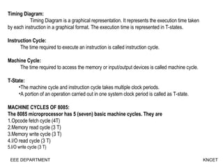
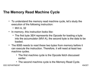
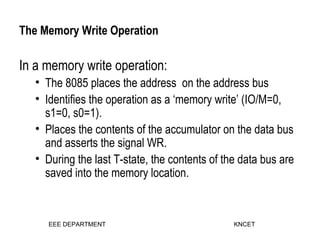
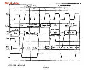
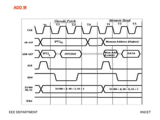
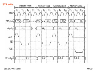
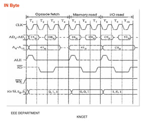
MACHINE CYCLES AND TIMING
DIAGRAM
Prepared By:
B.Saravana Manikandan,
Assistant Professor,
Kongunadu College of Engineering & Technology,
Trichy.
Timing Diagram:
Timing Diagram is a graphical representation. It represents the execution time taken
by each instruction in a graphical format. The execution time is represented in T-states.
Instruction Cycle:
      The time required to execute an instruction is called instruction cycle.
Machine Cycle:
      The time required to access the memory or input/output devices is called machine cycle.
T-State:
•The machine cycle and instruction cycle takes multiple clock periods.
•A portion of an operation carried out in one system clock period is called as T-state.
MACHINE CYCLES OF 8085:
The 8085 microprocessor has 5 (seven) basic machine cycles. They are
1.Opcode fetch cycle (4T)
2.Memory read cycle (3 T)
3.Memory write cycle (3 T)
4.I/O read cycle (3 T)
5.I/O write cycle (3 T)
EEE DEPARTMENT KNCET
Opcode Fetch Machine Cycle
• The first step of executing any instruction is the Opcode fetch cycle.
• In this cycle, the microprocessor brings in the instruction’s
Opcode from memory.
• To differentiate this machine cycle from the very similar
“memory read” cycle, the control & status signals are set
as follows:
• IO/M=0, S0 and S1 are both 1.
• This machine cycle has four T-states.
• The 8085 uses the first 3 T-states to fetch the opcode.
• T4 is used to decode and execute it.
• It is also possible for an instruction to have 6 T-states in an
Opcode fetch machine cycle.
EEE DEPARTMENT
KNCET
The Memory Read Machine Cycle
• To understand the memory read machine cycle, let’s study the
execution of the following instruction:
• MVI A, 32
• In memory, this instruction looks like:
• The first byte 3EH represents the Opcode for loading a byte
into the accumulator (MVI A), the second byte is the data to be
loaded.
• The 8085 needs to read these two bytes from memory before it
can execute the instruction. Therefore, it will need at least two
machine cycles.
• The first machine cycle is the Opcode fetch discussed
earlier.
• The second machine cycle is the Memory Read Cycle.
EEE DEPARTMENT KNCET
The Memory Write Operation
In a memory write operation:
• The 8085 places the address on the address bus
• Identifies the operation as a ‘memory write’ (IO/M=0,
s1=0, s0=1).
• Places the contents of the accumulator on the data bus
and asserts the signal WR.
• During the last T-state, the contents of the data bus are
saved into the memory location.
EEE DEPARTMENT KNCET
MVI B, data
EEE DEPARTMENT
KNCET
INR M
EEE DEPARTMENT
ADD M
EEE DEPARTMENT KNCET
STA addr
EEE DEPARTMENT KNCET
IN Byte
EEE DEPARTMENT
KNCET
EEE DEPARTMENT
KNCET

Machine cycles

  • 1.
    MACHINE CYCLES ANDTIMING DIAGRAM Prepared By: B.Saravana Manikandan, Assistant Professor, Kongunadu College of Engineering & Technology, Trichy.
  • 2.
    Timing Diagram: Timing Diagramis a graphical representation. It represents the execution time taken by each instruction in a graphical format. The execution time is represented in T-states. Instruction Cycle:       The time required to execute an instruction is called instruction cycle. Machine Cycle:       The time required to access the memory or input/output devices is called machine cycle. T-State: •The machine cycle and instruction cycle takes multiple clock periods. •A portion of an operation carried out in one system clock period is called as T-state. MACHINE CYCLES OF 8085: The 8085 microprocessor has 5 (seven) basic machine cycles. They are 1.Opcode fetch cycle (4T) 2.Memory read cycle (3 T) 3.Memory write cycle (3 T) 4.I/O read cycle (3 T) 5.I/O write cycle (3 T) EEE DEPARTMENT KNCET
  • 3.
    Opcode Fetch MachineCycle • The first step of executing any instruction is the Opcode fetch cycle. • In this cycle, the microprocessor brings in the instruction’s Opcode from memory. • To differentiate this machine cycle from the very similar “memory read” cycle, the control & status signals are set as follows: • IO/M=0, S0 and S1 are both 1. • This machine cycle has four T-states. • The 8085 uses the first 3 T-states to fetch the opcode. • T4 is used to decode and execute it. • It is also possible for an instruction to have 6 T-states in an Opcode fetch machine cycle. EEE DEPARTMENT KNCET
  • 4.
    The Memory ReadMachine Cycle • To understand the memory read machine cycle, let’s study the execution of the following instruction: • MVI A, 32 • In memory, this instruction looks like: • The first byte 3EH represents the Opcode for loading a byte into the accumulator (MVI A), the second byte is the data to be loaded. • The 8085 needs to read these two bytes from memory before it can execute the instruction. Therefore, it will need at least two machine cycles. • The first machine cycle is the Opcode fetch discussed earlier. • The second machine cycle is the Memory Read Cycle. EEE DEPARTMENT KNCET
  • 5.
    The Memory WriteOperation In a memory write operation: • The 8085 places the address on the address bus • Identifies the operation as a ‘memory write’ (IO/M=0, s1=0, s0=1). • Places the contents of the accumulator on the data bus and asserts the signal WR. • During the last T-state, the contents of the data bus are saved into the memory location. EEE DEPARTMENT KNCET
  • 6.
    MVI B, data EEEDEPARTMENT KNCET
  • 7.
  • 8.
  • 9.
  • 10.
  • 11.