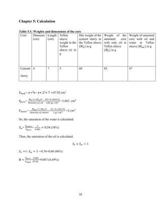
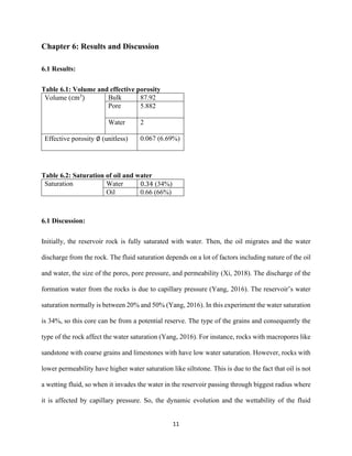
1. College of Engineering
Faculty of petroleum Engineering
Petroleum Fluid Properties Laboratory
PENG212L
Dean Stark Plug Size
Name: Ruba Alsoheil - ID: 201801530
Submitted to: Dr. Jamil Mahfoud
Date: 19-Jan-202
2. Table of Content:
List of Figures……………………………………………………………………………………...i
List of Tables……………………………………………………………………………………....ii
Chapter 1: Introduction……………………………………………………………………………1
1.1 Theory and Definitions………………………………………………………………………...1
1.2 Objective……………………………………………………………………………………...2
Chapter 2: Apparatus………………………………………………………………….…………...3
Chapter 3: Other Equipment..……………………………………………………………………..6
Chapter 4: Procedure………………………………………………………………………………8
Chapter 5: Calculation……………………………………………………………………………10
Chapter 6: Results and Discussion……………………………………………………………..…11
6.1 Table of Results……………………………………………………………………………....11
6.2 Discussion…………………………………………………………………………………....11
Chapter 7: Errors and Recommendations……………………………...…………………………13
7.1 Errors…………………………………………………………………………………………13
7.2 Recommendations..…………………………………………………………………………..13
Chapter 8: Conclusion……………………………………………………………………………14
References………………………………………………………………………………………..15
3. i
List of Figures:
Figure 2.1: Dean Stark Plug Size…………………………………………………………………3
Figure 3.1: Ruler…………………………………………………………………………………..6
Figure 3.2: Spatula……………………………………………………………………………...…6
Figure 3.3: Beakers……………………………………………………….……………………….6
Figure 3.4: Digital Balance………………………………………………………………………..7
Figure 3.5: Toluene………………………………………………………………………………..7
4. ii
List of Tables:
Table 5.1: Weights and dimensions of the core…………………………………………………10
Table 6.1: Volume and effective porosity……………………………………………………….11
Table 6.2: Saturation of oil and water……………………………………………………………11
5. 1
Chapter 1: Introduction
1.1 Theory:
Porosity and permeability are very important petrophysical factors which should be determined in
order to characterize the reservoir rock. Effective porosity represents the maximum capacity in
which fluids can be stored in. However, quantifying the availability of the fluid in the rock is
related to fluid saturation (Dandekar, 2011).
𝑓𝑙𝑢𝑖𝑑 𝑆𝑎𝑡𝑢𝑟𝑎𝑡𝑖𝑜𝑛 =
𝑇𝑜𝑡𝑎𝑙 𝑣𝑜𝑙𝑢𝑚𝑒 𝑜𝑓 𝑓𝑙𝑢𝑖𝑑
𝑉𝑜𝑙𝑢𝑚𝑒 𝑜𝑓 𝑡ℎ𝑒 𝑝𝑜𝑟𝑒
Moreover, different fluids can be present in the reservoir like water, oil, and gas. The summation
of the saturation of each fluid should be equal to one. Fluid saturation aids in determining the
quantity of recoverable hydrocarbon. Also, overestimating the water saturation lead to mistakenly
abandoning a potential reserve or underestimating can lead to economical loss in the project
(Dandekar, 2011). Furthermore, oil saturation is very important when choosing the right EOR
which aims to increase the production of the oil in the reservoir and reduce the production of water
(Dandekar, 2011). There are different types of saturation for oil. For instance, critical oil saturation
which is the value that saturation should exceed in order to permit the flow of oil (Ahmed, 2006).
Other types like residual oil saturation which is oil saturation after water or gas injection (Ahmed,
2006). Similarly, critical gas saturation is when the gas starts flowing after it get liberated below
the bubble point. Fluid saturation is measured directly and indirectly like well-logging (Ahmed,
2006). Moreover, apparatus used to measure fluid saturation are like Retort distillation or Dean
stark plug size apparatus (Dandekar, 2011). In this experiment Dean stark plug size apparatus is
used.
6. 2
1.2 Objective:
The main purpose of the apparatus used to know the water saturation which helps in deriving the
oil and the gas saturation.
7. 3
Chapter 2: Apparatus
Figure 2.1: Dean Stark Plug Size (Mahfoud, 2021)
The apparatus helps in knowing the liquid’s saturation in core, for it separates both liquids in
different beakers with known saturation and dry weight and volume of water.
Dryer
Clip
Inlet for 𝐻2𝑂
outlet for 𝐻2𝑂
Syphon Top
level
Graduated
Burette
Stopcock
Heater
Teflon
Sleeve
+
cement
Collar/
lid/ Seal
Glass
holder
Condenser
Inclined side arm
Trap
Round
Flask
Metallic Mesh
Pumice Stone
powder
Silica granular
8. 4
▪ Heater: heats the solution which leads to the evaporation of toluene of density 0.87 g/𝑐𝑚3
at 110ºC and 𝐻2𝑂 of density 0.87 g/𝑐𝑚3
at 100ºC. However, the temperature should be
limited in a certain range without over-heating the mixture and this can be done by adding
boiling chips.
▪ Round Flask: It has the core or the Teflon with the cement slurry and toluene solvent, and
it can handle the heat.
▪ Collar: it prevents any loss in the vapor where it prevents its escape by sealing the standard
flask well.
▪ Stand: It holds the standard flask.
▪ Condenser: After the vapor of the mixture reaches the condenser, due to flow of cold water
from the inlet to outlet around the vapor, this leads to the vapor’s condensation.
▪ Trap: It consists of the graduated tube where toluene and water will be separated due to
their different densities.
▪ Stopcock: In order to prevent water from flowing back to the inclined side arm, the
stopcock is opened where water’s volume in the graduated tube can be decreased by
draining it by rotating the stopcock which can control water’s flow.
▪ Inclined side arm: The vapor passes through it, and toluene since it has less density can
reflux to the boiling flask through it.
▪ Teflon Sleeve: It is considered as a core in the experiment, for it is has cement.
▪ Pumice stone powder: It is added to the toluene solution to assure a smooth boiling
procedure.
9. 5
▪ Silica granular: aids in preventing the turbidity due to the difference in temperature in the
condenser where it is placed in the dryer and helps determining the time of the evaporation
of certain components by getting dark.
11. 7
Figure 3.4: Digital Balance
Figure 3.5: Toluene (Altmann Analytics, n.d.)
• Ruler: is used to measure the dimensions, length and diameter.
• Spatula: It is used to add pumice stone powder to the beakers and stir the mixture. It is
used to add silica granular to the dryer.
• Beaker: contains the mixture which consists of pumice stone powder and toluene solvent
• Digital Balance: measures the saturated and the dry weight of cement slurry in the Teflon
sleeve
• Toluene: It is the solvent used to extract the liquids from the core
12. 8
Chapter 4: Procedure
▪ Measure the sample’s dimensions, length and diameter, with a ruler
▪ On a digital balance, weigh the Teflon, then weigh the Teflon with the cement dry
▪ Then, saturate the sample with oil and measure its saturated weight
▪ Saturate the sample with oil and water and measure its weight
▪ In a round flask pour 500 ml of toluene
▪ Then, add 20 ml of pumice stone
▪ Put the metallic mesh inside the round flask
▪ Then put the Teflon sleeve with the cement slurry or the core on the top of it
▪ The round flask is then locked with the inclined side arm after rotating the lid
▪ Install the condenser and the dryer
▪ Put silica gel in the dryer to help in humidity absorption
▪ Connect the inlet responsible for providing relatively cold water and the outlet
▪ Make sure that the connections are sealed and connected in the right way
▪ Turn ON the water-supply
▪ Turn ON the heater where it leads to the evaporation of the liquids
▪ Decrease the temperature of the heater if the you notice that the silica gel gets darker
quickly
▪ Regulate the temperature based of silica gel’s color
▪ The water, toluene, and the oil start to evaporite
▪ The vapor passes through the inclined cylinder to the condenser where it condenses
forming three layers where the bottom is water, middle is oil, and the top is toluene
13. 9
▪ Open the stopcock to drain the graduated burette from water to assure that the oil does not
reflux back to the round flask and only toluene refluxes to the round flask
▪ At the end, note down the water and the oil volume
▪ Turn OFF the heater and the water-supply
▪ Clean the round beaker and the dryer
▪ Disconnect the apparatus and place it back in place
14. 10
Chapter 5: Calculation
Table 5.1: Weights and dimensions of the core
Core Diameter
(cm)
Length
(cm)
Teflon
sleeve
weight in the
Teflon
sleeve (t) in
g
Dry weight of the
cement slurry in
the Teflon sleeve
(𝑊𝑑) in g
Weight of the
saturated core
with only oil in
Teflon sleeve
(𝑊
𝑜) in g
Weight of saturated
core with oil and
water in Teflon
sleeve (𝑊
𝑜𝑤) in g
Cement
slurry
4 7 5 60 65 67
𝑉𝑏𝑢𝑙𝑘= 𝜋 𝑟2
h= 𝜋× 22
× 7 =87.92 cm3
𝑉
𝑝𝑜𝑟𝑒=
𝑊𝑜−𝑡−𝑊𝑑+𝑡
𝐷𝑒𝑛𝑠𝑖𝑡𝑦 𝑜𝑓 𝑜𝑖𝑙
=
65−5−(60+5)
0.85 𝑔/ 𝑐𝑚3
= 5.882 𝑐𝑚3
𝑉𝑤𝑎𝑡𝑒𝑟=
𝑊𝑜𝑤−𝑡−𝑊𝑜+𝑡
𝐷𝑒𝑛𝑠𝑖𝑡𝑦 𝑜𝑓 𝑤𝑎𝑡𝑒𝑟
=
67−5−(65+5)
1 𝑔/ 𝑐𝑚3
=2 𝑐𝑚3
So, the saturation of the water is calculated.
𝑆𝑤=
𝑉𝑤𝑎𝑡𝑒𝑟
𝑉𝑝𝑜𝑟𝑒
=
2
5.882
= 0.34 (34%)
Then, the saturation of the oil is calculated.
𝑆𝑜 + 𝑆𝑤 = 1
𝑆𝑜 =1- 𝑆𝑤 = 1 −0.34=0.66 (66%)
∅ =
𝑉𝑝𝑜𝑟𝑒
𝑉𝑏𝑢𝑙𝑘
=
5.882
87.92
=0.067 (6.69%)
15. 11
Chapter 6: Results and Discussion
6.1 Results:
Table 6.1: Volume and effective porosity
Volume (cm3
) Bulk 87.92
Pore 5.882
Water 2
Effective porosity ∅ (unitless) 0.067 (6.69%)
Table 6.2: Saturation of oil and water
Saturation Water 0.34 (34%)
Oil 0.66 (66%)
6.1 Discussion:
Initially, the reservoir rock is fully saturated with water. Then, the oil migrates and the water
discharge from the rock. The fluid saturation depends on a lot of factors including nature of the oil
and water, the size of the pores, pore pressure, and permeability (Xi, 2018). The discharge of the
formation water from the rocks is due to capillary pressure (Yang, 2016). The reservoir’s water
saturation normally is between 20% and 50% (Yang, 2016). In this experiment the water saturation
is 34%, so this core can be from a potential reserve. The type of the grains and consequently the
type of the rock affect the water saturation (Yang, 2016). For instance, rocks with macropores like
sandstone with coarse grains and limestones with have low water saturation. However, rocks with
lower permeability have higher water saturation like siltstone. This is due to the fact that oil is not
a wetting fluid, so when it invades the water in the reservoir passing through biggest radius where
it is affected by capillary pressure. So, the dynamic evolution and the wettability of the fluid
16. 12
influence water saturation in the rock (Gueguen & Palciauskas, 1994). Furthermore, the pores’
size and the micro-porosity distribution is not uniform in the rock which leads to different water
saturation id different core sample were taken from different wells in the same field. Also, the
characteristics of the crude oil affects the saturation (Yang, 2016). For instance, oil that are
characterized by being more viscous, they lead to high water saturation in the rocks. Also, gas is
not a wetting fluid, but it has lighter viscosity which affects the gas saturation.
17. 13
Chapter 7: Errors and Recommendations
7.1 Errors:
▪ Forgetting to put pumice powder in the toluene solvent
▪ The water coming from the inlet is warm
▪ Not putting silica gel in the dryer
▪ Not monitoring the change in color of the silica gel which leads to the process happening
too fast or too slow
▪ The oil goes back to the round flask, due to increase in its volume
▪ The lid is not sealed well which leads to escape of the vapor
7.2 Recommendations:
▪ Put pumice stone powder in the toluene
▪ Make sure that the water coming from the inlet is relatively cold
▪ Monitor the change in color of the silica gel
▪ Open the stopcock to drain the water when the oil volume is about to reach the syphon top
level
▪ Make sure all the connections are sealed well
18. 14
Chapter 8: Conclusion
Determining the water saturation and the saturation of the fluids in the reservoir is very significant.
It helps in classifying the reservoir in order to know if it is feasible economically and in identifying
the uncertainty. Furthermore, there are a lot of factors which affect the water and oil saturation like
wettability, porosity, and the dynamic system. Different rocks have different water saturation since
they have different characteristics.
19. 15
References
Ahmed, T. (2006). Reservoir Engineering Handbook. Amsterdam: Elsevier.
Altmann Analytics. (n.d.). TOLUENE R. G., REAG. ACS, REAG. ISO,REAG. PH.Eur., Glass
Bottle, 1 L. Retrieved from: https://www.analytics-shop.com/gb/rd32249-1l-gb.html
Dandekar, A. (2011). Petroleum Reservoir Rock and Fluid Properties. London: Taylor & Francis.
Gueguen, Y &., Palciauskas, V. (1994). Introduction to physics of Rocks. Chichester: Princetone
University Press.
Mahfoud, J. (2021). Dean Stark Plug Size. Retrieved from:
https://lms.pu.edu.lb/sites/12020FALL15290/Documents/Dean%20stark%20plug%20size.pdf
Xi, K. (2018). Factors influencing oil saturation and exploration fairways in the lower cretaceous
Quantou Formation tight sandstones, Southern Songliao Basin, China. Energy Exploration &
Exploitation. DOI: 10.1177/0144598717751181
Yang, S. (2016). Fundamentals of Petrophysics. Beijing: Springer.
Yu, X. et al. (2006). Clastic hydrocarbon reservoir sedimentology. Beijing: Springer.