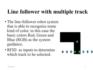
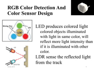
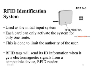
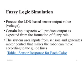
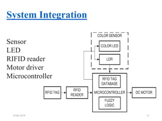
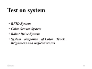
Design and Implementation of
RFID Line-Follower Robot System
with Color Detection Capability
using Fuzzy Logic
Presented by
Akhil K J
10-06-2018 1
About the paper
•Title
Design and Implementation of RFID Line-
Follower Robot System with Color Detection
Capability using Fuzzy Logic
•Authors
M B. Nugraha [Telkom University Bandung, Indonesia]
Rizki Ardianto P [Telkom University Bandung, Indonesia]
Denny Darlis [Telkom University Bandung, Indonesia]
Year: 2015
10-06-2018 2
Introduction:-
•Industrial mobilization and
transportation system (forklift)
•AGV (Automated Guided Vehicle)
•Line- follower robot.
• LED and LDR- based color sensor (Fuzzy
Logic)
• RFID-based identification/authorization
system
10-06-2018 3
Industrial mobilization and
transportation system
Limitation
•Manually operated
• Time,
• precision and
• operator/user authorization
10-06-2018 4
AGV (Automated
Guided Vehicle)
• Automatically guided from one point to another
in industries
• Used for the mobilization of raw materials and
products.
• Only moves through pre defined paths.
E.g. Line follower robot
10-06-2018 5
Working of AGV in industries
10-06-2018 6
Line follower robot
10-06-2018 7
• Flows a track of dark line.
• Light sensor is used to detect the path.
• Used in industry as AGV
• It can only pass through the single line.
• Simple in construction and accurate
tracking can obtain.
Line follower with multiple track
• The line-follower robot system
that is able to recognize some
kind of color, in this case the
basic colors Red, Green and
Blue (RGB) as the system
guidance.
• RFID as inputs to determine
which track to be selected.
10-06-2018 8
LED produces colored light
colored objects illuminated
with light in same color, will
reflect more light intensity than
if it is illuminated with other
color.
LDR sense the reflected light
from the track
RGB Color Detection And
Color Sensor Design
10-06-2018 9
• Used as the initial input system
• Each card can only activate the system for
only one route.
• This is done to limit the authority of the user.
• RFID tags will send its ID information when it
gets electromagnetic signals from a
compatible device, RFID reader.
10-06-2018 10
RFID Identification
System
Fuzzy Logic Simulation
• Process the LDR-based sensor output value
(voltage),
• Certain input system will produce output as
expected from the formation of fuzzy rule.
• The system uses inputs from sensors and generates
motor control that makes the robot can move
according to the guide lines
Table : Sensor Response for Each Color
10-06-2018 11
System Integration
10-06-2018 12
Sensor
LED
RIFID reader
Motor driver
Microcontroller
Test on system
10-06-2018 13
• RFID System
• Color Sensor System
• Robot Drive System
• System Response of Color Track
Brightness and Reflectiveness
RFID System
10-06-2018 14
Color Sensor System
10-06-2018 15
Robot Drive System
10-06-2018 16
System Response of Color
Track Brightness and Reflectiveness
10-06-2018 17
Limitations in this concept
1. It only discuss with tracks of three coloures.
2. Branching of the tracks are not explained
3. Description and testing of only prototype is
given.
4. The program or the logic loaded in the
microcontroller is not given.
5. Obstacle avoiding facility is not included.
10-06-2018 18
Suggestions to improve this idea
• Include obstacle avoiding facility
• Use track with secondary colours
• Include object detection capability
• Include ANN technology
• Branching
10-06-2018 19
CONCLUSION
The system is designed for the mobilization in
industries.(AGV)
It increase the utilization by increasing the number of
tracks.
The tracks are selected by an external input (RFID)
Tracks are detected by coloured light and LDR
assembly
The system consist of sensors, motor driver, RFID
reader and microcontroller.
 Tests on the system for controlling parameter and
physical conditions
10-06-2018 20
FUZZY SETS
10-06-2018 21
Three fuzzy sets for input and one fuzzy set for
output using triangular membership function
are created
10-06-2018 22
Sugeno-type Fuzzy Interference was chosen for the
process of formulating the mapping from the given
inputs to the output.
For defuzzification process, all consequent
membership functions are represented by singleton
spikes.
The weighted average (WA) of these singletons is
used to get the crisp output. The equation
RULES
RULE
IF RED
IS
AND GREEN
IS
AND BLUE
IS
THEN OUTPUT IS
1 Low Low Medium Blue
2 Low Low High Blue
3 Low Medium High Blue
4 Medium Low High Blue
5 Low Medium Low Green
6 Low High Low Green
7 Low High Medium Green
8 Medium High Low Green
9 Medium Low Low Red
10 High Low Low Red
11 High Medium Low Red
12 High Low Medium Red
13 Medium Medium High Blue
14 Medium High Medium Green
15 High Medium Medium Red
10-06-2018 23
10-06-2018 24
Figure 5.1: A Fuzzy Logic System.
PC with MATLAB
software
Microcontroller Colour Sensor
readingoutput
Serial
Comm
Figure 5.1.1. Colour Sensor-MATLAB setup.
A fuzzy logic system (FLS) can be defined as the nonlinear
mapping of an input data set to a scalar output data. A FLS
consists of four main parts: fuzzifier, rules, inference engine,
and defuzzifier. These components and the general architecture
of a FLS is shown
THANKYOU
10-06-2018 25

Line follower robot with color detection capability

  • 1.
    Design and Implementationof RFID Line-Follower Robot System with Color Detection Capability using Fuzzy Logic Presented by Akhil K J 10-06-2018 1
  • 2.
    About the paper •Title Designand Implementation of RFID Line- Follower Robot System with Color Detection Capability using Fuzzy Logic •Authors M B. Nugraha [Telkom University Bandung, Indonesia] Rizki Ardianto P [Telkom University Bandung, Indonesia] Denny Darlis [Telkom University Bandung, Indonesia] Year: 2015 10-06-2018 2
  • 3.
    Introduction:- •Industrial mobilization and transportationsystem (forklift) •AGV (Automated Guided Vehicle) •Line- follower robot. • LED and LDR- based color sensor (Fuzzy Logic) • RFID-based identification/authorization system 10-06-2018 3
  • 4.
    Industrial mobilization and transportationsystem Limitation •Manually operated • Time, • precision and • operator/user authorization 10-06-2018 4
  • 5.
    AGV (Automated Guided Vehicle) •Automatically guided from one point to another in industries • Used for the mobilization of raw materials and products. • Only moves through pre defined paths. E.g. Line follower robot 10-06-2018 5
  • 6.
    Working of AGVin industries 10-06-2018 6
  • 7.
    Line follower robot 10-06-20187 • Flows a track of dark line. • Light sensor is used to detect the path. • Used in industry as AGV • It can only pass through the single line. • Simple in construction and accurate tracking can obtain.
  • 8.
    Line follower withmultiple track • The line-follower robot system that is able to recognize some kind of color, in this case the basic colors Red, Green and Blue (RGB) as the system guidance. • RFID as inputs to determine which track to be selected. 10-06-2018 8
  • 9.
    LED produces coloredlight colored objects illuminated with light in same color, will reflect more light intensity than if it is illuminated with other color. LDR sense the reflected light from the track RGB Color Detection And Color Sensor Design 10-06-2018 9
  • 10.
    • Used asthe initial input system • Each card can only activate the system for only one route. • This is done to limit the authority of the user. • RFID tags will send its ID information when it gets electromagnetic signals from a compatible device, RFID reader. 10-06-2018 10 RFID Identification System
  • 11.
    Fuzzy Logic Simulation •Process the LDR-based sensor output value (voltage), • Certain input system will produce output as expected from the formation of fuzzy rule. • The system uses inputs from sensors and generates motor control that makes the robot can move according to the guide lines Table : Sensor Response for Each Color 10-06-2018 11
  • 12.
    System Integration 10-06-2018 12 Sensor LED RIFIDreader Motor driver Microcontroller
  • 13.
    Test on system 10-06-201813 • RFID System • Color Sensor System • Robot Drive System • System Response of Color Track Brightness and Reflectiveness
  • 14.
  • 15.
  • 16.
  • 17.
    System Response ofColor Track Brightness and Reflectiveness 10-06-2018 17
  • 18.
    Limitations in thisconcept 1. It only discuss with tracks of three coloures. 2. Branching of the tracks are not explained 3. Description and testing of only prototype is given. 4. The program or the logic loaded in the microcontroller is not given. 5. Obstacle avoiding facility is not included. 10-06-2018 18
  • 19.
    Suggestions to improvethis idea • Include obstacle avoiding facility • Use track with secondary colours • Include object detection capability • Include ANN technology • Branching 10-06-2018 19
  • 20.
    CONCLUSION The system isdesigned for the mobilization in industries.(AGV) It increase the utilization by increasing the number of tracks. The tracks are selected by an external input (RFID) Tracks are detected by coloured light and LDR assembly The system consist of sensors, motor driver, RFID reader and microcontroller.  Tests on the system for controlling parameter and physical conditions 10-06-2018 20
  • 21.
    FUZZY SETS 10-06-2018 21 Threefuzzy sets for input and one fuzzy set for output using triangular membership function are created
  • 22.
    10-06-2018 22 Sugeno-type FuzzyInterference was chosen for the process of formulating the mapping from the given inputs to the output. For defuzzification process, all consequent membership functions are represented by singleton spikes. The weighted average (WA) of these singletons is used to get the crisp output. The equation
  • 23.
    RULES RULE IF RED IS AND GREEN IS ANDBLUE IS THEN OUTPUT IS 1 Low Low Medium Blue 2 Low Low High Blue 3 Low Medium High Blue 4 Medium Low High Blue 5 Low Medium Low Green 6 Low High Low Green 7 Low High Medium Green 8 Medium High Low Green 9 Medium Low Low Red 10 High Low Low Red 11 High Medium Low Red 12 High Low Medium Red 13 Medium Medium High Blue 14 Medium High Medium Green 15 High Medium Medium Red 10-06-2018 23
  • 24.
    10-06-2018 24 Figure 5.1:A Fuzzy Logic System. PC with MATLAB software Microcontroller Colour Sensor readingoutput Serial Comm Figure 5.1.1. Colour Sensor-MATLAB setup. A fuzzy logic system (FLS) can be defined as the nonlinear mapping of an input data set to a scalar output data. A FLS consists of four main parts: fuzzifier, rules, inference engine, and defuzzifier. These components and the general architecture of a FLS is shown
  • 25.

Editor's Notes

  • #4 Mamdani's fuzzy inference method is the most commonly seen fuzzy methodology. Mamdani's method was among the first control systems built using fuzzy set theory. It was proposed in 1975 by Ebrahim Mamdani [1] as an attempt to control a steam engine and boiler combination by synthesizing a set of linguistic control rules obtained from experienced human operators.
  • #12 using fuzzy logic because it changes depend on light conditions and have a volatile measurement value. From the MATLAB simulation results, data sensors test and implementation of fuzzy rules are used to obtain the employment patterns in a system
  • #13 system recognizes which path to follow based on the brightest color. The initial input is received from the RFID reader and then the system will activate which color LED to be used.
  • #16 Color sensor detection results in Table 4 show that the system recognizes which path to follow based on the brightest color reflection received by the sensor.
  • #17 Table 5 shows the results of testing when the system moves from the starting point to the destination point. The system is tested using different motor drive PWM values and sensor reading rates to obtain the optimal condition of the system. From the test results can be seen that the optimal conditions for the system is on the PWM value of 100% and a detection rate of 70ms which will result in speed of the robot movement from the starting point to the destination point at 0,083m/s.
  • #18 This study also testing and analyze which track condition is applicable for the system operation. Color brightness were separated into 3 type of brightness; high, normal and low. And for the reflectiveness, there are 3 type of material used for testing; normal white paper, glossy photo paper and grey newsprint paper. Result from table 7 shows for white paper, normal and high color brightness still applicable for the system and highbrightness level has the optimum value for system operation
  • #21  The system also have optimum result of the color line detection and successfully move from start to stop with 70ms sensor refresh rate and 100% PWM value resulting to 0.08m/s movement speed.