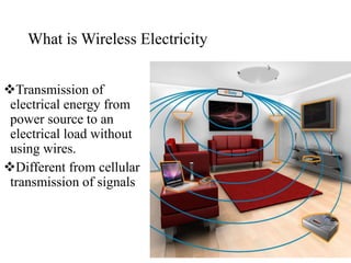
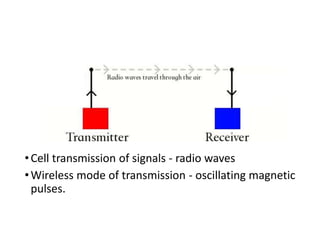
This document summarizes a seminar presentation on wireless electricity. It begins by defining wireless electricity as the transmission of electrical energy from a power source to an electrical load without wires. It then discusses the history of wireless electricity, including Nikola Tesla's early experiments using resonant transformers. The document explains the physics behind wireless electricity transmission using magnetic field resonance and inductive coupling between coils. It presents Witricity as an example technology and discusses challenges such as coil design and production costs. Applications mentioned include wirelessly charging electronic devices, lighting systems, electric vehicles and medical implants.


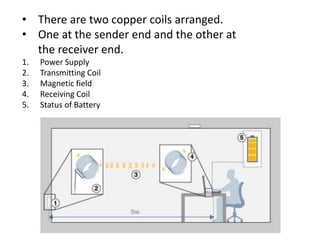


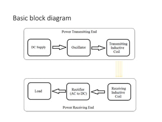

![Sequence of flow of Power
Step 1
A circuit [A] attached to the wall socket converts the
DC current to 2 megahertz and feeds it to the
transmitting coil [B].
The oscillating current inside the transmitting coil
causes the coil to emit a 2 -megahertz magnetic field](https://image.slidesharecdn.com/lifitechnology-150513044611-lva1-app6892/85/WIRELESS-ELECTRICITY-23-320.jpg)
![Continued…
Step 2
The receiving coil [C] is designed to resonate at the
same frequency
Magnetic induction takes place.
Receiving coil picks up the energy of the first coil's
magnetic field.](https://image.slidesharecdn.com/lifitechnology-150513044611-lva1-app6892/85/WIRELESS-ELECTRICITY-24-320.jpg)
![Continued…
Step 3
The energy of the oscillating magnetic field
induces an electrical current in the receiving coil,
lighting the bulb [D].](https://image.slidesharecdn.com/lifitechnology-150513044611-lva1-app6892/85/WIRELESS-ELECTRICITY-25-320.jpg)


![Saminar[1][1]](https://cdn.slidesharecdn.com/ss_thumbnails/saminar11-160503131554-thumbnail.jpg?width=640&height=640&fit=bounds)


