Downloaded 90 times
![1
INTRODUCTION
The Research Design and Standards Organization {अनुसंधान अभिकल्प एवं मानक संगठन}
(RDSO) is an ISO 9001 research and development organization under the Ministry of
Railways of India, which functions as a technical adviser and consultant to the Railway Board,
the Zonal Railways, the Railway Production Units, RITES and IRCON International in respect
of design and standardization of railway equipment and problems related to railway construction,
operation and maintenance.
History
To enforce standardization and co-ordination between various railway systems in British India,
the Indian Railway Conference Association (IRCA) was set up in 1903. It was followed by the
establishment of the Central Standards Office (CSO) in 1930, for preparation of designs,
standards and specifications. However, till independence in 1947, most of the designs and
manufacture of railway equipment’s was entrusted to foreign consultants. After independence, a
new organization called Railway Testing and Research Centre (RTRC) was set up in 1952 at
Lucknow, for undertaking intensive investigation of railway problems, providing basic criteria
and new concepts for design purposes, for testing prototypes and generally assisting in finding
solutions for specific problems. In 1957, the Central Standards Office (CSO) and the Railway
Testing and Research Centre (RTRC) were integrated into a single unit named Research Designs
and Standards Organization (RDSO) under the Ministry of Railways with its headquarters at
Manak nagar, Lucknow.[1]
The status of RDSO was changed from an "Attached Office" to a
"Zonal Railway" on April 1, 2003, to give it greater flexibility and a boost to the research and
development activities.
The RDSO is headed by a Director General who ranks with a General Manager of a Zonal
Railway. The Director General is assisted by an Additional Director General and 23 Sr.
Executive Directors and Executive Directors, who are in charge of the 27 directorates: Bridges
and Structures, the Centre for Advanced Maintenance Technology (CAMTECH), Carriage,
Geotechnical Engineering, Testing, Track Design, Medical, EMU & Power Supply, Engine
Development, Finance & Accounts, Telecommunication, Quality Assurance, Personnel, Works,
Psycho-Technical, Research, Signal, Wagon Design, Electric Locomotive, Stores, Track
Machines & Monitoring, Traction Installation, Energy Management, Traffic, Metallurgical &
Chemical, Motive Power and Library & Publications. All the directorates except Defence
Research are located in Lucknow.](https://image.slidesharecdn.com/rdso-160825155655/85/RDSO-Training-1-320.jpg)
![1
INTRODUCTION
The Research Design and Standards Organization {अनुसंधान अभिकल्प एवं मानक संगठन}
(RDSO) is an ISO 9001 research and development organization under the Ministry of
Railways of India, which functions as a technical adviser and consultant to the Railway Board,
the Zonal Railways, the Railway Production Units, RITES and IRCON International in respect
of design and standardization of railway equipment and problems related to railway construction,
operation and maintenance.
History
To enforce standardization and co-ordination between various railway systems in British India,
the Indian Railway Conference Association (IRCA) was set up in 1903. It was followed by the
establishment of the Central Standards Office (CSO) in 1930, for preparation of designs,
standards and specifications. However, till independence in 1947, most of the designs and
manufacture of railway equipment’s was entrusted to foreign consultants. After independence, a
new organization called Railway Testing and Research Centre (RTRC) was set up in 1952 at
Lucknow, for undertaking intensive investigation of railway problems, providing basic criteria
and new concepts for design purposes, for testing prototypes and generally assisting in finding
solutions for specific problems. In 1957, the Central Standards Office (CSO) and the Railway
Testing and Research Centre (RTRC) were integrated into a single unit named Research Designs
and Standards Organization (RDSO) under the Ministry of Railways with its headquarters at
Manak nagar, Lucknow.[1]
The status of RDSO was changed from an "Attached Office" to a
"Zonal Railway" on April 1, 2003, to give it greater flexibility and a boost to the research and
development activities.
The RDSO is headed by a Director General who ranks with a General Manager of a Zonal
Railway. The Director General is assisted by an Additional Director General and 23 Sr.
Executive Directors and Executive Directors, who are in charge of the 27 directorates: Bridges
and Structures, the Centre for Advanced Maintenance Technology (CAMTECH), Carriage,
Geotechnical Engineering, Testing, Track Design, Medical, EMU & Power Supply, Engine
Development, Finance & Accounts, Telecommunication, Quality Assurance, Personnel, Works,
Psycho-Technical, Research, Signal, Wagon Design, Electric Locomotive, Stores, Track
Machines & Monitoring, Traction Installation, Energy Management, Traffic, Metallurgical &
Chemical, Motive Power and Library & Publications. All the directorates except Defence
Research are located in Lucknow.](https://image.slidesharecdn.com/rdso-160825155655/75/RDSO-Training-1-2048.jpg)
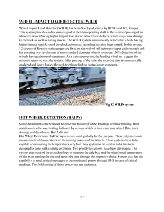
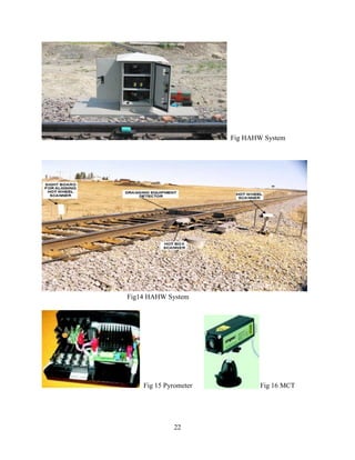

The document provides information on the Research Designs and Standards Organization (RDSO) in India. It discusses that RDSO is the sole research and development organization of Indian Railways that functions as a technical advisor. It oversees the development of new designs, technologies, and standards for materials used in railways. The document outlines some of RDSO's key laboratories and facilities for testing railway equipment and conducting research. It also summarizes some technology mission projects aimed at improving railway safety in areas such as detecting overheated wheels, improving visibility in fog, satellite-based train tracking, and bogie monitoring systems.