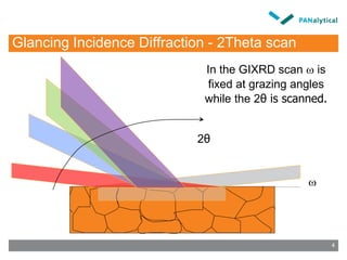
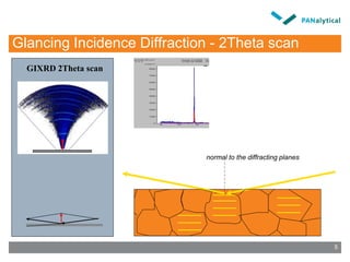
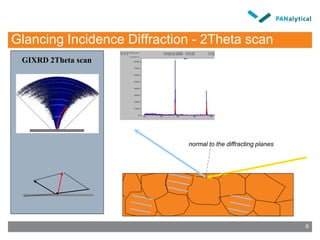
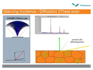
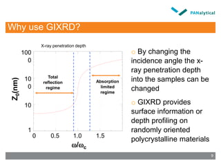
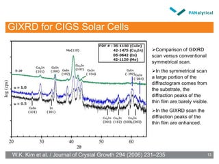
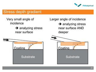
- Grazing incidence X-ray diffraction (GIXRD) is a technique that allows analyzing thin film samples by varying the incident angle of the X-rays to change their penetration depth.
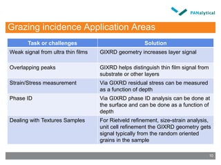
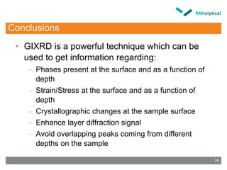
- GIXRD provides enhanced signals from thin film layers compared to conventional XRD and helps distinguish thin film peaks from substrate peaks. It can also be used to analyze phases, stress, and crystal structure as a function of depth.
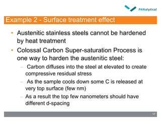
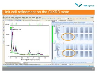
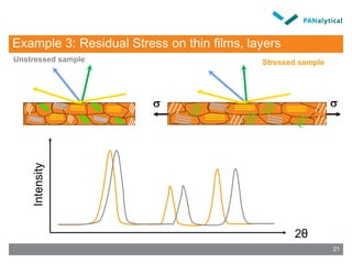
- Examples showed how GIXRD allowed analyzing phase composition and residual stress at different depths in thin film solar cell structures and revealed surface treatment effects in a stainless steel sample.
![GIXRD - Thin film depth profiling phase analysis
Position [°2Theta] (Copper (Cu))
10 20 30 40 50 60 70
Counts
0
400
1600
0
400
1600
0
400
1600
3600
, Incident angle
0.45 deg
1.00 deg
2.00 deg
CIGS
Mo
ZnO
ZnO
CIGS
ZnO
Mo
ZnO
CIGS
ZnO
Mo
Position [°2Theta] (Copper (Cu))
10 20 30 40 50 60
0
0
0
0
0
14](https://image.slidesharecdn.com/gixrd-12881577445025-phpapp02/85/Gixrd-14-320.jpg)
![GIXRD - Thin film depth profiling phase analysis
Position [°2Theta] (Copper (Cu))
10 20 30 40 50 60 70
Counts
0
400
1600
0
400
1600
0
400
1600
3600
, Incident angle
0.45 deg
1.00 deg
2.00 deg
CIGS
Mo
ZnO
ZnO
CIGS
ZnO
Mo
ZnO
CIGS
ZnO
Mo
Position [°2Theta] (Copper (Cu))
10 20 30 40 50 60
0
0
0
0
0
0
0
15](https://image.slidesharecdn.com/gixrd-12881577445025-phpapp02/85/Gixrd-15-320.jpg)
![GIXRD - Thin film depth profiling phase analysis
Position [°2Theta] (Copper (Cu))
10 20 30 40 50 60 70
Counts
0
400
1600
0
400
1600
0
400
1600
3600
, Incident angle
0.45 deg
1.00 deg
2.00 deg
CIGS
Mo
ZnO=0.45
ZnO
CIGS
ZnO
Mo
=1
ZnO
CIGS
ZnO
Mo
=2
16](https://image.slidesharecdn.com/gixrd-12881577445025-phpapp02/85/Gixrd-16-320.jpg)
![Depth profiling GIXRD-Austenitic stainless steel
Position [°2Theta] (Copper (Cu))
40 50 60 70 80 90 100
Counts
0
1000
0
2000
4000
0
500
1000
0
1000
0
2000
Incidence angle
0.5 0
0.8 0
1.0 0
2.0 0
0.3 0
18](https://image.slidesharecdn.com/gixrd-12881577445025-phpapp02/85/Gixrd-18-320.jpg)
![GIXRD - Austenitic stainless steel – Zoom in
Position [°2Theta] (Copper (Cu))
40 45 50 55
Counts
0
1000
0
2000
4000
0
500
1000
0
1000
0
2000
Incidence angle
0.5 0
0.8 0
1.0 0
2.0 0
0.3 0
19](https://image.slidesharecdn.com/gixrd-12881577445025-phpapp02/85/Gixrd-19-320.jpg)
![Stress with depth in CdTe layer of solar cell
0 2 4 6 8 10 12
-120
-100
-80
-60
-40
-20
ResidualStress[MPa]
Grazing Angle [degrees]
20 30 40 50 60 70 80 90 100 110 120 130 140
2Theta (°)
0
100
400
900
1600
2500
3600
Intensity(counts)
20 30 40 50 60 70 80 90 100 110 120 130 140
2Theta (°)
0
400
1600
3600
6400
Intensity(counts)
20 30 40 50 60 70 80 90 100 110 120 130 140
2Theta (°)
0
400
1600
3600
6400
Intensity(counts)
=0.1
=1
=5
23](https://image.slidesharecdn.com/gixrd-12881577445025-phpapp02/85/Gixrd-23-320.jpg)


![1138 schnopper[1]](https://cdn.slidesharecdn.com/ss_thumbnails/trqooqurqcw9tvydz38u-signature-fabe374f978bfb273f92443e2c8243d3e294d623a7c677008fe136d7284f57a9-poli-140825181533-phpapp01-thumbnail.jpg?width=640&height=640&fit=bounds)


