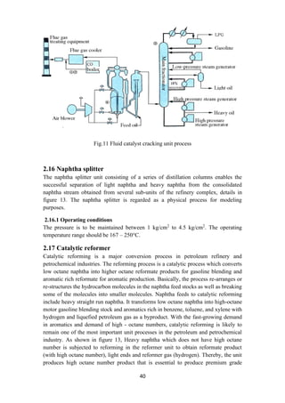
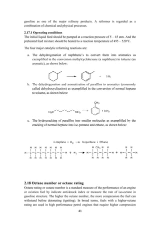
The document provides an overview of modern petroleum refining processes, highlighting the evolution of the industry and the importance of technological advancements. It discusses various aspects of crude oil, including classifications based on location, density, and sulfur content, as well as characteristics like viscosity and pour point. Additionally, the document emphasizes the significance of petroleum in global energy consumption and its role in chemical production, underlining its critical importance to modern civilization.
+ as well as other oligomeric species. Furthermore, the solubility of
ferrous hydroxide and the composition of its soluble components depends on pH. In
general, solubility in the solvent phase can be given only for a specific solute which is
thermodynamically stable, and the value of the solubility will include all the species
in the solution (in the example above, all the iron-containing complexes).
Factors affecting solubility.
Solubility is defined for specific phases. For example, the solubility of aragonite and](https://image.slidesharecdn.com/lecturenotesinmodernpetroleumrefiningprocesses-230129175316-09122da0/85/Lecture-Notes-in-Modern-Petroleum-Refining-Processes-13-320.jpg)
![18
1.11.1 Types of aromatic compounds
The overwhelming majority of aromatic compounds are compounds of carbon, but
they need not be hydrocarbons.
a. Heterocyclics
In heterocyclic aromatics (heteroaromats), one or more of the atoms in the aromatic
ring is of an element other than carbon. This can lessen the ring's aromaticity, and thus
(as in the case of furan) increase its reactivity. Other examples include pyridine,
pyrazine, imidazole, pyrazole, oxazole, thiophene, and their benzannulated analogs
(benzimidazole, for example).
b. Polycyclics
Polycyclic aromatic hydrocarbons are molecules containing two or more simple
aromatic rings fused together by sharing two neighboring carbon atoms. Examples are
naphthalene, anthracene and phenanthrene.
Substituted aromatics Many chemical compounds are aromatic rings with other things
attached. Examples include trinitrotoluene (TNT), acetylsalicylic acid (aspirin),
paracetamol, and the nucleotides of DNA.
c. Atypical aromatic compounds
Aromaticity is found in ions as well: the cyclopropenyl cation (2e system), the
cyclopentadienyl anion (6e system), the tropylium ion (6e) and the cyclooctatetraene
dianion (10e). Aromatic properties have been attributed to non-benzenoid compounds
such as tropone. Aromatic properties are tested to the limit in a class of compounds
called cyclophanes.
A special case of aromaticity is found in homoaromaticity where conjugation is
interrupted by a single sp³ hybridized carbon atom.
When carbon in benzene is replaced by other elements in borabenzene, silabenzene,
germanabenzene, stannabenzene, phosphorine or pyrylium salts the aromaticity is still
retained. Aromaticity also occurs in compounds that are not carbon-based at all.
Inorganic 6 membered ring compounds analogous to benzene have been synthesized.
Silicazine (Si6H6) and borazine (B3N3H6) are structurally analogous to benzene, with
the carbon atoms replaced by another element or elements. In borazine, the boron and
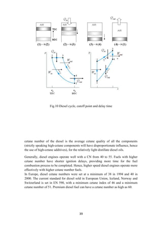
nitrogen atoms alternate around the ring.
Metal aromaticity is believed to exist in certain metal clusters of aluminium. Möbius
aromaticity occurs when a cyclic system of molecular orbitals, formed from pπ atomic
orbitals and populated in a closed shell by 4n (n is an integer) electrons, is given a
single half-twist to correspond to a Möbius strip. Because the twist can be left-handed
or right-handed, the resulting Möbius aromatics are dissymmetric or chiral. Up to now
there is no doubtless proof that a Möbius aromatic molecule was synthesized.
Aromatics with two half-twists corresponding to the paradromic topologies, first
suggested by Johann Listing, have been proposed by Rzepa in 2005. In carbo-benzene
the ring bonds are extended with alkyne and allene groups [1]
.](https://image.slidesharecdn.com/lecturenotesinmodernpetroleumrefiningprocesses-230129175316-09122da0/85/Lecture-Notes-in-Modern-Petroleum-Refining-Processes-18-320.jpg)
![21
aroma. Some are carcinogenic.
These different molecules are separated by fractional distillation at an oil refinery to
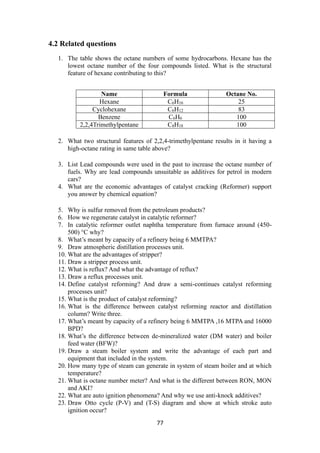
produce gasoline, jet fuel, kerosene, and other hydrocarbons. For example, 2,2,4-
trimethylpentane (isooctane), widely used in gasoline, has a chemical formula of
C8H18 and it reacts with oxygen exothermically:
a. The number of various molecules in an oil sample can be determined in
laboratory. The molecules are typically extracted in a solvent, then separated
in a gas chromatograph, and finally determined with a suitable detector, such
as a flame ionization detector or a mass spectrometer.
b. Incomplete combustion of petroleum or gasoline results in production of toxic
byproducts. Too little oxygen results in carbon monoxide. Due to the high
temperatures and high pressures involved, exhaust gases from gasoline
combustion in car engines usually include nitrogen oxides which are
responsible for creation of photochemical smog.
1.13 Heat of combustion
At a constant volume the heat of combustion of a petroleum product can be
approximated as follows:
Qv = 12,400 − 2,100g2
………………………….(4)
where [Qv] is measured in cal/gram and [g] is the specific gravity at 60°F.
1.13.1 Thermal conductivity
The thermal conductivity of petroleum-based liquids can be modeled as follows:
where K is measured in BTU. hr-1
ft-2
, t is measured in °F and g is the specific gravity
at 60°F.
1.13.2 Spreading
Oil that spreads and moves, when lighter than water, forming slicks that spread on the
surface, on streams, rivers and ponds in percentages that are influenced by gravity,
surface tension, viscosity, point of fluidity, winds and currents.
The temperature is another crucial variable to control spreading due to the
dependency that viscosity has on temperature. One should note that crude oils vary
widely in composition and their behavior on the ocean also varies. Even viscous crude
oils can spread quickly in thin layers. The action of the currents and wind spreads and
breaks the slicks into mobile portions of oil that will have the largest amounts (thicker)
near their leading edges.
Both wind and current affect the movement of the portions in the water. The effect of
the currents is 100% in rivers, while that of the wind is around 3% of the wind speed.
The effect of the wind is little felt in rivers, contrary to what happens in a pond where
the wind is the predominant element in oil displacement.](https://image.slidesharecdn.com/lecturenotesinmodernpetroleumrefiningprocesses-230129175316-09122da0/85/Lecture-Notes-in-Modern-Petroleum-Refining-Processes-21-320.jpg)
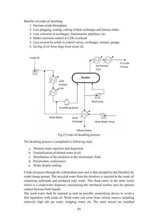
![26
upstream the emulsifying devices to improve the contact between the salt in the crude
oil and the wash water injected in the line.
The oil/water mixture is homogenously emulsified in the emulsifying device. The
emulsifying device (as a valve) is used to emulsify the dilution water injected
upstream in the oil. The emulsification is important for contact between the salty
production water contained in the oil and the wash water. Then the emulsion enters
the Desalters where it separates into two phases by electrostatic coalescence.
The electrostatic coalescence is induced by the polarization effect resulting from an
external electric source. Polarization of water droplets pulls them out from oil-water
emulsion phase. Salt being dissolved in these water droplets, is also separated along
the way. The produced water is discharged to the water treatment system (effluent
water). It can also be used as wash water for mud washing process during operation.
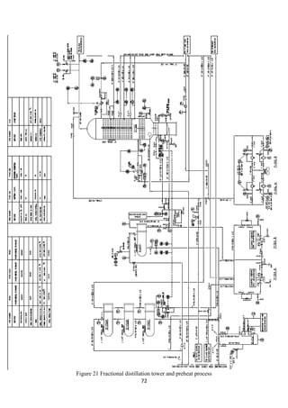
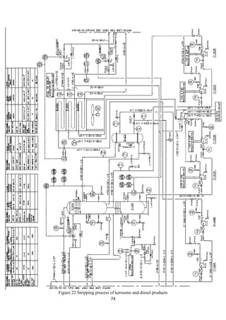
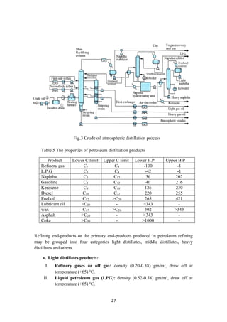
2.4 Crude distillation unit
The unit comprising of an atmospheric distillation column, side strippers, heat
exchanger network, feed de-salter and furnace as main process technologies enables
the separation of the crude into its various products. Usually, five products are
generated from the CDU namely gas + naphtha, kerosene, light gas oil, heavy gas oil
and atmospheric residue (figure 3). In some refinery configurations, terminologies
such as gasoline, jet fuel and diesel are used to represent the CDU products which are
usually fractions emanating as portions of naphtha, kerosene and gas oil. Amongst the
crude distillation products, naphtha, kerosene has higher product values than gas oil
and residue. On the other hand, modern refineries tend to produce lighter components
from the heavy products. Therefore, reactive transformations (chemical processes) are
inevitable to convert the heavy intermediate refinery streams into lighter streams.
Operating Conditions: The temperature at the entrance of the furnace where the crude
enters is 200 – 280°C. It is then further heated to about 330 – 370°C inside the
furnace. The pressure maintained is about 1 bar gauge [2]
.](https://image.slidesharecdn.com/lecturenotesinmodernpetroleumrefiningprocesses-230129175316-09122da0/85/Lecture-Notes-in-Modern-Petroleum-Refining-Processes-26-320.jpg)
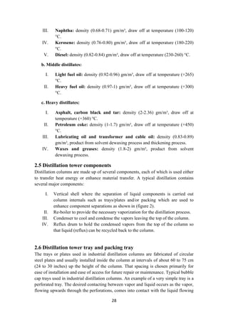
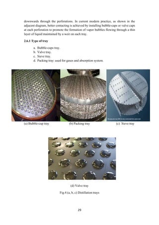
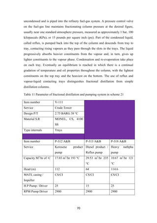
![31
the reflux drum. Some of this liquid is recycled back to the top of the column and this
is called the reflux.
Reflux refers to the portion of the overhead liquid product from a distillation column
or fractionator that is returned to the upper part of the column as shown in the
schematic diagram of a typical industrial distillation column. Inside the column, the
down flowing reflux liquid provides cooling and condensation of the up flowing
vapors thereby increasing the efficiency of the distillation column.
The more reflux provided for a given number of theoretical plates, the better is the
column's separation of lower boiling materials from higher boiling materials.
Conversely, for a given desired separation, the more reflux is provided, the fewer
theoretical plates are required. The condensed liquid that is removed from the system
is known as the distillate or top product.
Thus, there are internal flows of vapors and liquid within the column as well as
external flows of feeds and product streams, into and out of the column.
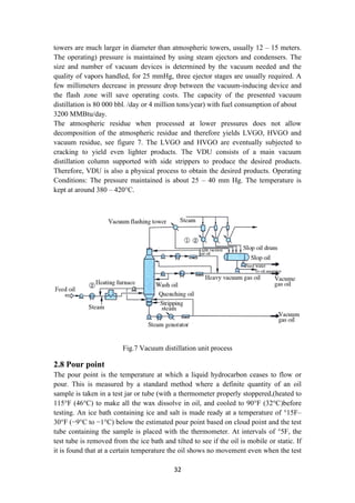
2.7 Vacuum distillation unit (VDU)
2.7.1 Process overview
Refineries today are facing new challenges in order to meet the requirements with
respect to environment, health and safety of the plant personnel and the quality of the
finished products.
With increasing crude oil prices, refineries are processing heavier, lower quality
crudes that set new challenges to further develop the processes and maximize the
yield of valuable distillates in an energy efficient way. Plant run-time targets are
increasing which sets more challenges for equipment reliability and process control.
Hydrocarbons should not be heated to too high temperature due to cracking reactions
that take place above about 400 °C. Coke deposits on piping and equipment increase
maintenance costs and reduce process unit run-time. Therefore, crude distillation
bottom (residue) is further processed in a vacuum column to recover additional
distillates, light and heavy vacuum gasoil as feedstock to cracking units or lube-oil
processing [3]
.
2.7.2 Three types of vacuum towers are used
1. Dry (no steam).
2. Wet without stripping.
3. Wet with stripping.
Distillation is carried out with absolute pressures in the tower flash zone area of 25 to
40 mmHg. To improve vaporization, the effective pressure is lowered even further by
the addition of steam to the furnace inlet and at the bottom of the vacuum tower. The
amount of stripping steam used is a function of the boiling range of the feed and the
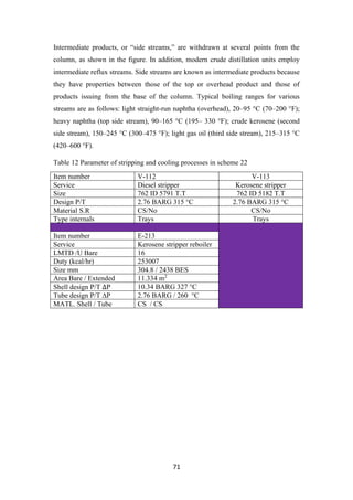
fraction vaporized as well as furnace outlet temperatures (380 – 420°C).) Vacuum](https://image.slidesharecdn.com/lecturenotesinmodernpetroleumrefiningprocesses-230129175316-09122da0/85/Lecture-Notes-in-Modern-Petroleum-Refining-Processes-31-320.jpg)
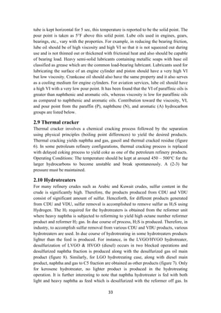
![34
this process, light ends from the reformer gas are stripped to enhance the purity of
hydrogen to about 92 % (figure 8). Conceptually, hydrotreating is regarded as a
combination of chemical and physical processes [4-6]
.
2.11 Operating conditions
The operating condition of a hydrotreater varies with the type of feed. For Naphtha
feed, the temperature may be kept at around 280-425°C and the pressure be
maintained at 200 – 800 psig.
Fig.8 Hydro-desulfurization unit process
S
2
H + H
-
R
2
SH + H
-
R
H2S + NaOH NaSH + H2O
2.11.1 Corrosion
The presence of mercaptan sulfur may cause corrosion in the fuel pipes and the engine
cylinder and produce sulfur dioxide during combustion. In the past, Merox (a catalytic
mercaptan oxidation method) treatment was done to convert corrosive mercaptans to
non-corrosive disulfide, but this did not remove the sulfur originally present in the
fuel. However, it did give rise to the formation of sulfur dioxide during combustion.
Since emission of sulfur dioxide is prohibited by environmental protection laws,
nowadays mercaptans and other sulfur compounds are mostly removed.
by a catalytic hydrodesulfurization unit in a refinery. The corrosive effects of other
organic compounds along with traces of sulfur-bearing compounds and additives must
be tested in the laboratory. The copper corrosion test similar to that described in the
testing of LPG is also carried out in the laboratory at standard temperature (50°C) for
3 h.
Catalyst
Heat](https://image.slidesharecdn.com/lecturenotesinmodernpetroleumrefiningprocesses-230129175316-09122da0/85/Lecture-Notes-in-Modern-Petroleum-Refining-Processes-34-320.jpg)
![36
The Merox reactor is a vertical vessel containing a bed of charcoal that have been
impregnated with the cobalt – base catalyst. The charcoal may be impregnated with
the catalyst in situ, or they may be purchased from market as pre-impregnated with
the catalyst. An alkaline environment is provided by caustic being pumped into
reactor on an intermittent, as needed basis.
The jet fuel or kerosene feedstock from the top of the caustic prewash vessel is
injected with compressed air and enters the top of the Merox reactor vessel along with
any injected caustic. The mercaptan oxidation reaction takes place as the feedstock
percolates downward over the catalyst. The reactor effluent flows through a caustic
settler vessel where it forms a bottom layer of caustic solution and an upper layer of
water-insoluble sweetened product.
The caustic solution remains in the caustic settler so that the vessel contains a
reservoir for the supply of caustic that is intermittently pumped into the reactor to
maintain the alkaline environment.
The sweetened product from the caustic settler vessel flows through a water wash
vessel to remove any entrained caustic as well as any other unwanted water-soluble
substances, followed by flowing through a salt bed vessel to remove any entrained
water and finally through a clay filter vessel. The clay filter removes any oil-soluble
substances, organometallic compounds (especially copper) and particulate matter,
which might prevent meeting jet fuel product specifications.
The pressure maintained in the reactor is chosen so that the injected air will
completely dissolve in the feedstock at the operating temperature [7-10]
.
The overall oxidation reaction that takes place in converting mercaptans to disulfides
is:
O
2
→ 2RSSR + 2H
2
RSH + O
4
The most common mercaptans removed are:
]
mercaptan
-
SH [m
3
CH
-
Methanethiol
]
]
mercaptan
-
SH [e
5
H
2
C
-
Ethanethiol
]
]
P mercaptan
-
SH [n
7
H
3
C
-
Propanethiol
-
1
]
]
mercaptan
3
[2C
3
CH(SH)CH
3
CH
-
Propanethiol
-
2
]
[Butanethiol - C4H9SH [n-butyl mercaptan]](https://image.slidesharecdn.com/lecturenotesinmodernpetroleumrefiningprocesses-230129175316-09122da0/85/Lecture-Notes-in-Modern-Petroleum-Refining-Processes-36-320.jpg)
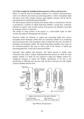
![47
in both premium and regular gasoline products are prepared by blending appropriate
amounts of n-butane, reformate, light naphtha, alkylate and light cracked naphtha as
shown in figure 15. These two products are by far the most profit-making products of
the modern refinery and henceforth emphasis is there to maximize their total products
while meeting the product specifications. The gasoil pool produces automotive diesel
and heating oil from kerosene (from CDU), LGO, LVGO and slurry [10]
. In the fuel oil
pool (figure 15), haring diesel, heavy fuel oil and bunker oil are produced from
LVGO, slurry and cracked residue.
Fig.15 Blending pools or Blending drum
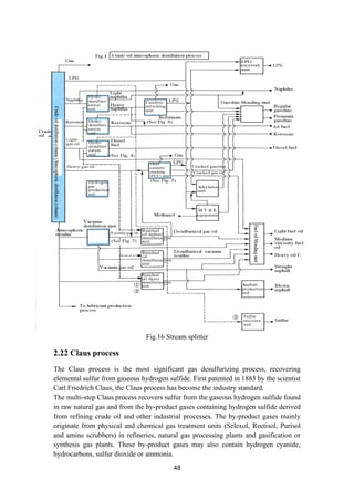
2.21 Stream splitters
To facilitate stream splitting, various stream splitters are used in the refinery
configuration. A kerosene splitter is used to split kerosene between the kerosene
product and the stream that is sent to the gas oil pool as in figure 16. Similarly, butane
splitter splits the n-butane stream into butanes entering LPG pool, gasoline pool and
isomerization unit.
Unlike naphtha splitter, these two splitters facilitate stream distribution and do not
have any separation processes built within them. With these conceptual diagrams to
represent the refinery, the refinery block diagram with the complicated interaction of
streams is presented in figure 16.](https://image.slidesharecdn.com/lecturenotesinmodernpetroleumrefiningprocesses-230129175316-09122da0/85/Lecture-Notes-in-Modern-Petroleum-Refining-Processes-47-320.jpg)
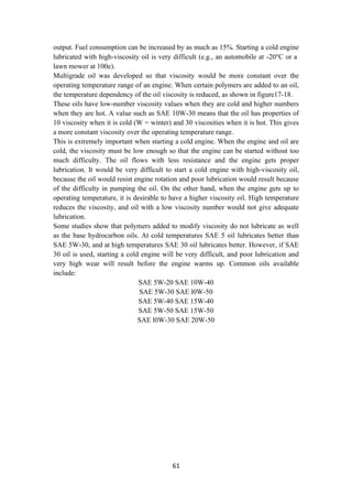
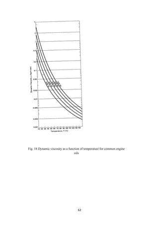
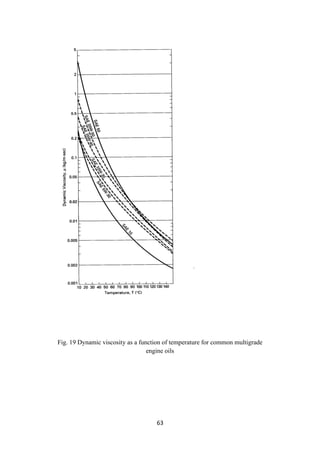
![58
which are suitable for use in high temperatures and the oxidizing environment of
engines. Load (weight to carry) and speed of the vehicles are also to be taken care of
before selecting a lube oil to apply. Usually, the temperature of an engine rises rapidly
during the startup and continues at that temperature during motion. Such a wide and
sudden change in temperature demands that the lubricant should have a high VI. In
addition to temperature fluctuations, lubricants are prone to oxidation and cracking,
leading to the formation of cokes, carbons, and gummy substances, which may
ultimately deposit on the engine, causing irreparable damage. In addition to engine
oils, different lubricants are applicable for other parts of the vehicle, such as the gears,
brake, clutch, and bearings. Gear boxes contain the gears immersed in lubricating oil
having low viscosity to reduce friction at high speed. The brake and clutch require
lubricating oils of low viscosity. Bearings are used in various parts of the automobile
from engine to wheels and require low to high viscous lubricants. At low temperatures
and high load, bearings at wheels are lubricated by grease. Since materials of
construction and type of engines vary with the make, appropriate lubricants are
selected and prescribed by the manufacturers. No single lubricant is therefore
applicable for all makes. Finished lubes are classified according to the Society of
Automotive Engineers’ (SAE). The viscosity of the lubricants and its variation with
temperature (VI) and the pour point are the important parameters to satisfy the
compatibility of application of lubes. Winter grades are classified as SAE numbers
from 0 to 25W as typical examples of cold temperatures and from 20 to 60 SAE
numbers for warming up the cranks of engines. A multigrade lubricant is a blend of
more than one type of lubricant. For example, SAE15W 50 is an example of a blend
of two grade oils. Usually, polymeric materials, such as ethylene propylene
copolymer, polymethyl acrylate, and butadiene, are added to these multigrade oils.
However, rigorous testing of appropriate lubes must be carried out on cars of different
makes in the testing laboratory or workshop for their suitability before prescribing
them for engines and other parts. Since the performance of these lubes may not be
satisfactory after a certain period of time due to degradation because of
contamination, reaction, physical and chemical changes in the property of the
ingredients or the base oils, it is inevitable that the lube must be drained out and
replaced with fresh stock. This drain out period must be specified for the prescribed
lubricants. The longer the drain out period, the more attractive the lubricant is in the
market [11][12]
.
3.6 Additives
Lubricants are comprised primarily of base oils and additives. Grease is comprised of
base oils and additives along with thickeners.
The following is a brief description of lubricant additives and their functions:
I. Anti-wear additive: Zinc dialkyldithiophosphate (ZDDP) is the most
common antiwear additive, although there are many zinc-free additives based
on sulfur and phosphorus that also impart anti-wear properties. The zinc-](https://image.slidesharecdn.com/lecturenotesinmodernpetroleumrefiningprocesses-230129175316-09122da0/85/Lecture-Notes-in-Modern-Petroleum-Refining-Processes-58-320.jpg)
![65
b. Non-soap Base
Polyuria, Modified betonies and other clays like Colloidal, silica, Organic
compounds Fluorinated compounds
3.7.2 Grease additives
The additives used in greases are very similar to those used in lubricating oils, which
are listed below. Some additives that you would expect to find in grease include
Antioxidants or oxidation inhibitors.
a. Corrosion inhibitors
l. 30 Color stabilizers Dyes.
ll. Film strength agents metal deactivators rust inhibitors stringiness additive’s
structure modifiers for soap-oil systems.
3.7.3 Grease Fillers
In addition to soap, base oil and additives, solid fillers can be added to grease to
enhance its lubricity and load carrying ability. Some of the fillers used in lubricating
greases are listed below:
1. Graphite colloidal flake powdered.
2. Lead powder molybdenum disulfide.
3. Red lead powder.
4. Zinc oxide.
5. Copper flake.
6. Zinc dust.
3.8 Finished products
Using the above intermediates, a variety of plastics, rubber, fiber, solvent, paint, etc,.
are manufactured. Polymerisation reactions are carried out for these monomers or
intermediates to various polymers, resinous and liquid products. Plastics are available
in the form of extrudates, granules, powders, beads, etc., from the manufacturing units
as the finished products. These are converted into plastic commodities, such as bags,
films, furniture, and products of various shapes and sizes by casting, molding, or
blowing machines, as the marketable products. Plastics are classified ed into two
types, namely, thermoplastic (or thermoplast) and thermosetting plastics or
(thermoset). Thermoplasts, usually linear in molecular structure, can be melted (or
softened) by heating and solidify ed (or hardened) by cooling. This heating and
cooling cycle can be repeated indefinitely without loss of the original properties. But
thermosets will be permanently transformed to a chemically cross linked or non-linear
structure and cannot be returned to their original property during a heating and
cooling cycle [13]
.](https://image.slidesharecdn.com/lecturenotesinmodernpetroleumrefiningprocesses-230129175316-09122da0/85/Lecture-Notes-in-Modern-Petroleum-Refining-Processes-65-320.jpg)