Downloaded 12 times


![33
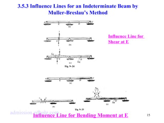
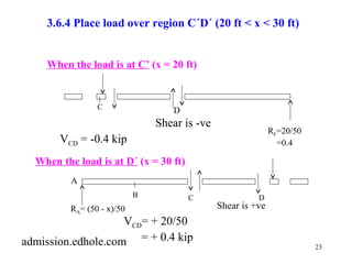
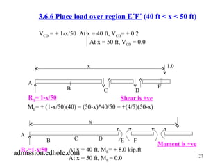
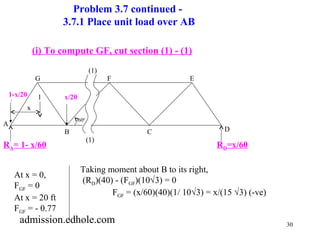
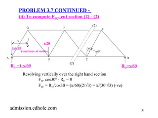
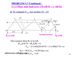
PROBLEM 3.7 Continued -
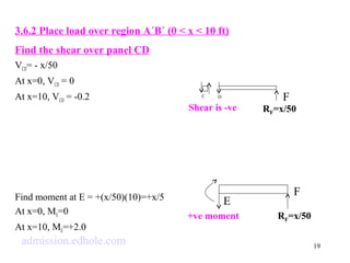
3.7.2 Place unit load over BC (20 ft < x <40 ft)
[Section (1) - (1) is valid for 20 < x < 40 ft]
(i) To compute FGF use section (1) -(1)
G F E
(1)
(1)
Taking moment about B, to its left,
(RA)(20) - (FGF)(10Ö3) = 0
FGF = (20RA)/(10Ö3) = (1-x/60)(2 /Ö3)
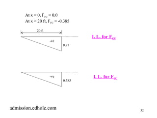
At x = 20 ft, FFG = 0.77 (-ve)
At x = 40 ft, FFG = 0.385 (-ve)
A
B C D
x
(40-x)/20
1 (x-20)/20
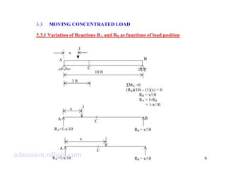
reactions at nodes
20 ft
RA=1-x/60 RD(x-20) (40-x) =x/60
admission.edhole.com](https://image.slidesharecdn.com/b-140925011117-phpapp02/85/B-tech-admission-in-india-33-320.jpg)
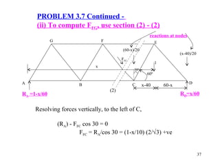
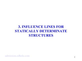
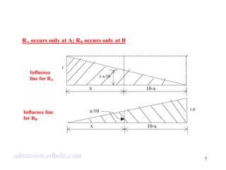
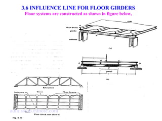
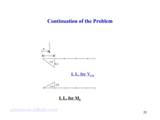
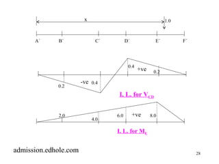
![3.8 MAXIMUM SHEAR FORCE AND BENDING MOMENT
39
UNDER A SERIES OF CONCENTRATED LOADS
a1 a2 a3
x
PR= resultant load
a1 a2 a3
C.L.
x
Taking moment about A,
RE ´ L = PR ´[L/2 - (x -x)]
R PR
E = - +
(L / 2 x x)
L
x
PR= resultant load
L/2
L RE
A
B C D
E
P1
P2 P3 P4
P1 P2
P3 P4
RA
admission.edhole.com](https://image.slidesharecdn.com/b-140925011117-phpapp02/85/B-tech-admission-in-india-39-320.jpg)
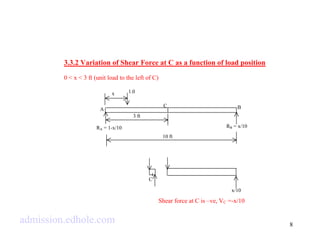
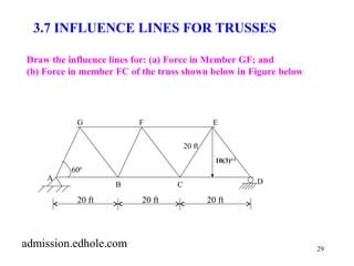
![40
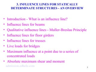
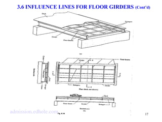
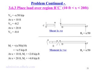
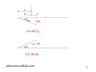
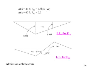
Taking moment about E,
R ´ L = P ´ L + x -
x
A R
R P
= R
+ -
M = R ´ L + x - P a + a - P ´
a
D A
P
= + - + - + - ´
0
[ / 2 ( )]
( / 2 )
1 1 2 2 2
( / 2 )( / 2 ) ( ) ( )
L x x P
P
dM
=
= + - + + -
0 R ( / 2 ) R
( / 2 )( 1)
L x x L x
= + - - -
[( / 2) ( / 2) ]
P
L
i e x x
- =
. ., 2 0
x 2
x
2
( / 2 ) ( )
1 1 2 2 2
=
x x
L x
L
L
dx
L x x L x P a a P a
L
L x x
L
R
D
R
A
=
The centerline must divide the distance between the resultant of
all the loads in the moving series of loads and the load considered
admuisnsdieorn w.ehdichho mlea.cxoimmum bending moment occurs.](https://image.slidesharecdn.com/b-140925011117-phpapp02/85/B-tech-admission-in-india-40-320.jpg)

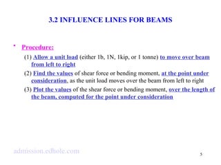
This document discusses influence lines for statically determinate structures. It begins with an introduction to influence lines and how they describe the variation of forces like reactions, shear, and bending moment at a point on a structure. It then provides examples of calculating influence lines for beams, floor girders, and trusses. The examples show how to determine the influence lines by considering equilibrium of the structure as a unit load is moved along its length. Plots of the influence lines illustrate how the internal forces vary based on the load location.