Casting Processes
• Introductionto casting processes, Patterns: Pattern materials,
types of pattern, allowances pattern design,
• Moulding sand, Properties of moulding sands, Core making,
• Melting practices and furnaces,
• Pouring and Gating system design, Numerical estimation to
find mold filling time, Riser design and placement,
• Principles of cooling and solidification of casting, Directional
and Progressive solidification Estimation of solidification rate,
• Cleaning and Finishing of casting, Defects and remedies,
Principle and equipments of Permanent mould casting,
Investment casting, Centrifugal casting, Continuous casting
3.
Introduction to castingprocesses
• Casting is a manufacturing process in which a liquid material
is usually poured into a mold, which contains a hollow cavity
of the desired shape, and then allowed to solidify.
• The solidified part is also known as a casting, which is ejected
or broken out of the mold to complete the process.
• Casting is one of the oldest manufacturing processes.
4.
Advantages of Casting
Can create complex part geometries
– Molten material can flow into very small sections so that
intricate shapes can be made by this process. As a result, many
other operations, such as machining, forging, and welding, can
be minimized.
Can create both external and internal shapes
Possible to cast practically any material: ferrous or non-
ferrous.
Near net shape
Size and weight of the product is not a limitation for the
casting process.
Some casting methods are suited to mass production
5.
Disadvantages of Casting
Limitationson mechanical properties
Poor dimensional accuracy and surface finish for some
processes; e.g., sand casting
Safety hazards to workers due to hot molten metals
Environmental problems
6.
Applications
• Transport: automobile,aerospace, railways and shipping.
• Heavy equipment: construction, farming and mining.
• Machine tools: machining, casting, plastics moulding, forging, extrusion
and forming.
• Plant machinery: chemical, petroleum, paper, sugar, textile, steel and
thermal plants.
• Defense: vehicles, artillery, munitions, storage and supporting equipment
• Electrical machines: motors, generators, pumps and compressors
• Municipal castings: pipes, joints, valves and fittings
• Household: appliances, kitchen and gardening equipment, furniture and
fittings
• Art objects: sculptures, idols, furniture, lamp stands and decorative
items.
7.
Casting process
Processin which molten metal flows by gravity or other
force into a mold where it solidifies in the shape of the mold
cavity
• The term casting also applies to the part made in the process
• Steps in casting seem simple:
1. Melt the metal
2. Pour it into a mold
3. Let it freeze
8.
Manufacturing Processes -I
Sand Casting Production Sequence
Figure: Steps in the production sequence in sand casting.
Pattern
• A fullsized model of the part, slightly enlarged to account for
‑
shrinkage and machining allowances in the casting
• Pattern materials:
– Wood - common material because it is easy to work, but it
warps
– Metal - more expensive to make, but lasts much longer
– Plastic - compromise between wood and metal
– Wax
– Ceramic
– Plaster of Paris
11.
Pattern Allowances
• Shrinkageallowance
• Draft allowance
• Distortion or camber allowance
• Rapping or Shaking allowance
• Finishing allowance
Manufacturing Processes - I
Types of pattern
Typesof patterns depend upon the following factors:
The shape and size of casting
No. of castings required
Method of moulding employed
Anticipated difficulty of moulding operation
1. Single piece(solid) pattern
Made from one piece and does not contain loose pieces or
joints.
Inexpensive.
Used for large size simple castings.
Pattern is accommodated either in the cope or in the drag.
Examples:
1. Bodies of regular shapes.
2. stuffling box of steam engine.
2. Split piecepattern
Patterns of intricate shaped castings cannot be made in one
piece because of the inherent difficulties associated with the
molding operations (e.g. withdrawing pattern from mould).
The upper and the lower parts of the split piece patterns are
accommodated in the cope and drag portions of the mold
respectively.
Parting line of the pattern forms the parting line of the mould.
22.
Split piece pattern
•Dowel pins are used for
keeping the alignment between
the two parts of the pattern.
• Examples:
1.Hallow cylinder
2.Taps and water stop cocks
etc.,
3. Loose piecepattern
Certain patterns cannot be withdrawn once they are embedded
in the molding sand. Such patterns are usually made with one
or more loose pieces for facilitating from the molding box and
are known as loose piece patterns.
Loose parts or pieces remain attached with the main body of
the pattern, with the help of dowel pins.
The main body of the pattern is drawn first from the molding
box and thereafter as soon as the loose parts are removed, the
result is the mold cavity.
4. Match platepattern
It consists of a match plate, on either side of which each
half of split patterns is fastened.
A no. of different sized and shaped patterns may be
mounted on one match plate.
The match plate with the help of locator holes can be
clamped with the drag.
After the cope and drag have been rammed with the
molding sand, the match plate pattern is removed from in
between the cope and drag.
27.
• Match platepatterns are normally used in machine molding.
• By using this we can eliminate mismatch of cope and drag
cavities.
Match plate pattern
28.
5. Sweep pattern
A sweep pattern is just a form made on a wooden board
which sweeps the shape of the casting into the sand all
around the circumference. The sweep pattern rotates about
the post.
Once the mold is ready, Sweep pattern and the post can be
removed.
Sweep pattern avoids the necessity of making a full, large
circular and costly three-dimensional pattern.
29.
• Making asweep pattern saves a lot of time and labor as
compared to making a full pattern.
• A sweep pattern is preferred for producing large casting of
circular sections and symmetrical shapes.
Sweep pattern
6. Gated pattern
The sections connecting different patterns serve as runner
and gates.
This facilitates filling of the mould with molten metal in a
better manner and at the same time eliminates the time and
labour otherwise consumed in cutting runners and gates.
A gated pattern can manufacture many casting at one time
and thus it is used in mass production systems.
Gated patterns are employed for producing small castings.
7. Skeleton pattern
•A skeleton pattern is the skeleton of a desired shape which
may be S-bend pipe or a chute or something else. The
skeleton frame is mounted on a metal base
• The skeleton is made from wooden strips, and is thus a
wooden work.
• The skeleton pattern is filled with sand and is rammed.
34.
• A strickle(board) assists in giving the desired shape to the
sand and removes extra sand.
• Skeleton patterns are employed for producing a few large
castings.
• A skeleton pattern is very economical, because it involves less
material costs.
Skeleton pattern
35.
8. Follow boardpattern
• A follow board is a wooden board and is used for supporting a pattern
which is very thin and fragile and which may give way and collapse
under pressure when the sand above the pattern is being rammed.
• With the follow board support under the weak pattern, the drag is
rammed, and then the fallow board is with drawn, The rammed drag is
inverted, cope is mounted on it and rammed.
• During this operation pattern remains over the inverted drag and get
support from the rammed sand of the drag under it.
• Follow boards are also used for casting master patterns for many
applications.
9. Cope andDrag patterns
• A cope and drag pattern is another form of split pattern.
• Each half of the pattern is fixed to a separate metal/wood plate.
• Each half of the pattern(along the plate) is molded separately in a
separate molding box by an independent molder or moulders.
• The two moulds of each half of the pattern are finally assembled and
the mould is ready for pouring.
• Cope and drag patterns are used for producing big castings which as
a whole cannot be conveniently handled by one moulder alone.
Foundry Sands
Silica (SiO2)or silica mixed with other minerals
• Good refractory properties capacity to endure high
‑
temperatures
• Small grain size yields better surface finish on the cast
part
• Large grain size is more permeable, allowing gases to
escape during pouring
• Irregular grain shapes strengthen molds due to
interlocking, compared to round grains
– Disadvantage: interlocking tends to reduce
permeability
40.
Binders Used withFoundry Sands
• Sand is held together by a mixture of water and bonding clay
– Typical mix: 90% sand, 7% clay and 3% water
• Other bonding agents also used in sand molds:
– Organic resins (e.g , phenolic resins)
– Inorganic binders (e.g , sodium silicate and phosphate)
• Additives are sometimes combined with the mixture to
increase strength and/or permeability
41.
Types of SandMold
• Green sand molds
‑ - mixture of sand, clay, and water;
– “Green" means mold contains moisture at time of pouring
• Dry sand mold
‑ - organic binders rather than clay
– And mold is baked to improve strength
• Skin dried mold
‑ - drying mold cavity surface of a green sand
‑
mold to a depth of 10 to 25 mm, using torches or heating
lamps
42.
Desirable Mold Properties
•Strength Ability of mold to maintain shape and resist erosion
‑
caused by the flow of molten metal. Depends on grain shape,
adhesive quality of binders
• Permeability to allow hot air and gases to pass through voids
‑
in sand
• Thermal stability ability of sand at the mold surface cavity to
‑
resist cracking and buckling on contact with molten metal
• Collapsibility ability to give way and allow casting to shrink
‑
without cracking the casting
• Reusability can sand from broken mold be reused to make
‑
other molds?
43.
Molding
• Mold isa container with cavity whose geometry determines part
shape
– Actual size and shape of cavity must be slightly oversized to allow
for shrinkage of metal during solidification and cooling
– Molds are made of a variety of materials, including sand, plaster,
ceramic, and metal
Sand Casting MoldTerms
• Mold consists of two halves:
– Cope = upper half of mold
– Drag = bottom half
• Mold halves are contained in a box, called a flask
• The two halves separate at the parting line
46.
Forming the MoldCavity
– Mold cavity is formed by packing sand around a pattern
– When the pattern is removed, the remaining cavity of the packed
sand has desired shape of cast part
– Wet sand is made by adding binder in the sand
47.
Making the SandMold
• The cavity in the sand mold is formed by packing sand
around a pattern, then separating the mold into two halves
and removing the pattern
• The mold must also contain gating and riser system
• If casting is to have internal surfaces, a core must be included
in mold
• A new sand mold must be made for each part produced
48.
Use of aCore in the Mold Cavity
• Cavity provides the external features of the cast part
• Core provides internal features of the part. It is placed
inside the mold cavity with some support.
• In sand casting, cores are generally made of sand
49.
Core in Mold
Acore is a full-scale model of interior surfaces of the part.
(a) Core held in place in the mold cavity by chaplets, (b) possible chaplet design,
(c) casting with internal cavity.
Furnace
• Heating mediaor device.
• Used for heating and melting.
• For providing heat to chemical reactions for
processes like cracking.
• The furnace may be heated by fuel as in many furnaces coke is
used as a fuel.
• some are operated by electrical energy e.g.
electric arc furnace.
52.
Furnaces for CastingProcesses
• Furnaces most commonly used in foundries:
– Cupolas
– Direct fuel-fired furnaces
– Crucible furnaces
– Electric-arc furnaces
– Induction furnaces
Cupolas
Vertical cylindrical furnaceequipped with tapping spout
near base
• Used only for cast irons
– Although other furnaces are also used, the largest tonnage
of cast iron is melted in cupolas
• The "charge," consisting of iron, coke, flux, and possible
alloying elements, is loaded through a charging door
located less than halfway up height of cupola
Crucible Furnaces
Metal ismelted without direct contact with burning fuel
mixture
• Sometimes called indirect fuel-fired furnaces
• Container (crucible) is made of refractory material or
high-temperature steel alloy
• Used for nonferrous metals such as bronze, brass, and
alloys of zinc and aluminum
• Three types used in foundries: (a) lift-out type, (b)
stationary, (c) tilting
57.
Crucible Furnaces
Three typesof crucible furnaces: (a) lift-out crucible, (b) stationary pot, from
which molten metal must be ladled, and (c) tilting-pot furnace.
Crucible Furnaces
Induction Furnaces
Uses alternatingcurrent passing through a coil to develop magnetic field in
metal
• Induced current causes rapid heating and melting
• Electromagnetic force field also causes mixing action in liquid metal
• Since metal does not contact heating elements, environment can be
closely controlled to produce molten metals of high quality and purity
• Melting steel, cast iron, and aluminum alloys are common applications
in
foundry work
61.
Gating System
It ischannel through which molten metal flows into cavity from
outside of mold
• Consists of a down-sprue, through which metal enters a runner
leading to the main cavity
• At the top of down-sprue, a pouring cup is often used to
minimize splash and turbulence as the metal flows into down-
sprue
62.
Requirement of GatingSystem
• Low flow velocity of molten metal.
• Insure complete filling of cavity.
• Prevent absorption of moisture while flow.
• Prevent formation of oxides.
• Prevent entry of slag, dross etc.
• Assist directional solidification.
• Should be practical and economical.
Types of Gates
1.Top Gate :- Open top gate, edge top gate, pencil gate, strainer core gate
2. Bottom Gate
3. Parting Gate
4. Step Gate
70.
• Top gate:-Atop gate is sometime called as drop gate because the
molten metal just drops on the sand in the bottom of mold.
• Edge gate:- Edge gate avoid the force full impinging action of
molten metal stream onto the mold cavity.
• Pencil gate:-It controls rate of metal flow .
• Gate with strainer core:-A strainer core is a perforated disc of
core sands or pre fired refractory placed.
Types of Gates
Pouring the MoltenMetal
Pouring rate should neither be high (may stuck the runner –
should match viscosity of the metal) nor very low that may
start solidifying on its way to the cavity
Turbulence should be kept to a minimum in order to ensure
smooth flow and to avoid mold damage and entrapment of
foreign materials. Also, turbulence causes oxidation at the
inner surface of cavity. This results in cavity damage and
poor surface quality of casting.
73.
Engineering Analysis ofPouring
•
1.v: velocity of liquid metal at base of sprue in cm/sec; g:
981cm/sec.sec; h: height of sprue in cm
2.v1: velocity at section of area A1; v2: velocity at section of
area A2
3.V: volume of mold cavity
74.
Manufacturing Processes -I
Calculation of Pouring Parameters
•
1. If sprue area at its entrance is 5cm2, compute metal velocity at sprue entrance.
2. Calculate velocity & flow rate of metal when metal is in the midway of sprue
75.
Manufacturing Processes -I
Riser
It is a reservoir in the mold which is a source of liquid metal to
compensate for shrinkage of the part during solidification
Most metals are less dense as a liquid than as a solid so castings
shrink upon cooling, which can leave a void at the last point to
solidify. Risers prevent this by providing molten metal to the
casting as it solidifies, so that the cavity forms in the riser and
not in the casting
Directional solidification and
Progressivesolidification
• Directional solidification and progressive solidification are
types of solidification within castings.
• Directional solidification is solidification that occurs from
farthest end of the casting and works its way towards the
sprue.
• Progressive solidification, also known as parallel
solidification, is solidification that starts at the walls of the
casting and progresses perpendicularly from that surface.
78.
Solidification time calculation
•Time required for solidification of molten metal in mould.
• Depends upon amount of heat in casting and surface area of
casting.
– Chvorinov’s rule
– Caine’s rule
• Height of cylindrical riser = 1.5 x diameter of riser
• As themetal in the riser must solidify at last, following
condition must be satisfied
• Not very accurate due to no consideration of shrinkage.
• Applicable only for short freezing range alloys like steel and pure metals.
Solidification time calculation
Chvorinov’s rule
81.
• As perthis rule, hyperbolic relationship between freezing
times and casting and riser volumes are used.
• The relative freezing time (X) is,
Solidification time calculation
Caine’s rule
Other Expendable Mold
Processes
Shell Molding
Vacuum Molding
Expanded Polystyrene Process
Investment Casting
Plaster Mold and Ceramic Mold Casting
85.
Shell Molding
Casting processin which the cavity (& gating
system) is a thin shell of sand held together by
thermosetting resin binder
Steps in shell molding: (1) a match plate or cope and drag
‑ ‑ ‑ ‑
metal pattern is heated and placed over a box containing
sand mixed with thermosetting resin.
part
86.
Shell Molding
Steps inshell molding: (2) box is inverted so that sand and
‑
resin fall onto the hot pattern, causing a layer of the
mixture to partially cure on the surface to form a hard
shell; (3) box is repositioned so that loose uncured
particles drop away;
87.
Shell Molding
Steps inshell molding: (4) sand shell is heated in oven for
‑
several minutes to complete curing; (5) shell mold is
stripped from the pattern;
88.
Shell Molding
Steps inshell molding: (6) two halves of the shell mold are
‑
assembled, supported by sand or metal shot in a box, and pouring
is accomplished; (7) the finished casting with sprue removed.
89.
Advantages and Disadvantages
Advantages of shell molding:
Smoother cavity surface permits easier flow of
molten metal and better surface finish
Good dimensional accuracy - machining often
not required
Mold collapsibility minimizes cracks in casting
Can be mechanized for mass production
Disadvantages:
More expensive metal pattern
Difficult to justify for small quantities
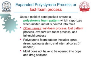
Expanded Polystyrene Processor
lost foam process
‑
Uses a mold of sand packed around a
polystyrene foam pattern which vaporizes
when molten metal is poured into mold
Other names: lost foam process, lost pattern
‑
process, evaporative foam process, and
‑
full mold process
‑
Polystyrene foam pattern includes sprue,
risers, gating system, and internal cores (if
needed)
Mold does not have to be opened into cope
and drag sections
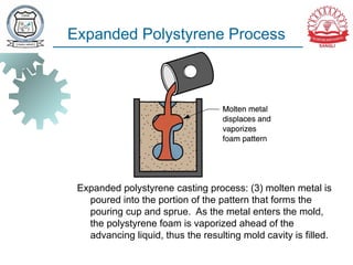
Expanded Polystyrene Process
Expandedpolystyrene casting process: (3) molten metal is
poured into the portion of the pattern that forms the
pouring cup and sprue. As the metal enters the mold,
the polystyrene foam is vaporized ahead of the
advancing liquid, thus the resulting mold cavity is filled.
96.
Advantages and Disadvantages
Advantages of expanded polystyrene process:
Pattern need not be removed from the mold
Simplifies and speeds mold making,
‑
because two mold halves are not required
as in a conventional green sand mold
‑
Disadvantages:
A new pattern is needed for every casting
Economic justification of the process is
highly dependent on cost of producing
patterns
97.
Expanded Polystyrene Process
Applications:
Mass production of castings for automobile
engines
Automated and integrated manufacturing
systems are used to
1. Mold the polystyrene foam patterns and
then
2. Feed them to the downstream casting
operation
98.
Investment Casting
(Lost WaxProcess)
A pattern made of wax is coated with a refractory
material to make mold, after which wax is
melted away prior to pouring molten metal
"Investment" comes from a less familiar
definition of "invest" - "to cover completely,"
which refers to coating of refractory material
around wax pattern
It is a precision casting process - capable of
producing castings of high accuracy and
intricate detail
99.
Investment Casting
Steps ininvestment casting: (1) wax patterns are produced, (2)
several patterns are attached to a sprue to form a pattern tree
100.
Investment Casting
Steps ininvestment casting: (3) the pattern tree is coated with a thin
layer of refractory material, (4) the full mold is formed by covering
the coated tree with sufficient refractory material to make it rigid
101.
Investment Casting
Steps ininvestment casting: (5) the mold is held in an inverted position
and heated to melt the wax and permit it to drip out of the cavity, (6)
the mold is preheated to a high temperature, the molten metal is
poured, and it solidifies
102.
Investment Casting
Steps ininvestment casting: (7) the mold is broken away
from the finished casting and the parts are separated
from the sprue
103.
Investment Casting
A onepiece compressor stator with 108 separate airfoils made by
‑
investment casting
104.
Advantages and Disadvantages
Advantages of investment casting:
Parts of great complexity and intricacy can
be cast
Close dimensional control and good surface
finish
Wax can usually be recovered for reuse
Additional machining is not normally
required this is a net shape process
‑
Disadvantages
Many processing steps are required
Relatively expensive process
105.
Centrifugal Casting
Mouldis rotated rapidly about its central axis as the
metal is pored into it.
Centrifugal force plays major role in shaping and
feeding of the casting.
C.F. helps to distribute the molten metal evenly to all
surfaces and separates the slag from out flowing
molten metal.
Three types:
1. True Centrifugal 2. Semi Centrifugal 3.
Centrifuge
#39 Silica sand comes in variety of grain sizes, each one has its own benefits
#40 1. Clay is a naturally occurring material composed primarily of fine-grained minerals. It show plasticity through a variable range of water content, and which can be hardened when dried and/or fired. The binding properties of clay are generally low compared with cement and, as already noted, reversible with water
3. Resins are hydrocarbon secretion of some plants, possessing good adhesive properties
4. Sodium Silicate Na2SiO3 (water glass or liquid glass)
#41 Green -> possess sufficient strength for most applications; good permeability, collapsibility, and reusability. Least expensive
Dry-sand -> Baked from 200 -320C. More strength and also hardened cavity; better dimensional accuracy
Skin-dried -> cost in between of previous two
#42 Collapsibility: This is also ability to remove sand from casting during cleaning
#47 Cores are made of green sand, dry sand, or fusible material (for injection molding only)
#49 Like pattern, shrinkage allowances are also provided in core.
It is usually made of compacted sand, metal
Chaplet -> A small metal insert or spacer used in molds to provide core support during casting process in order to avoid core lift due to buoyancy force of pouring metal.
Chaplets are made of metal with melting temperature higher than the casting metal
On solidification, the chaplet becomes bonded into the casting. The protruded part of chaplet is cut-off from the casting.
#75 Figure (right) Sprues and Riser formed in a bronze casting
#84 Shell molding, also known as shell-mold casting,[1] is an expendable mold casting process that uses a resin covered sand to form the mold. As compared to sand casting, this process has better dimensional accuracy, a higher productivity rate, and lower labor requirements. It is used for small to medium parts that require high precision
Vacuum molding, commonly known as vacuforming, is a simplified version of thermoforming, whereby a sheet of plastic is heated to a forming temperature, stretched onto or into a single-surface mold, and held against the mold by applying vacuum between the mold surface and the sheet.
Expanded Polystyrene is a packing or cushioning material
Investment casting is an industrial process based on and also called lost-wax casting.
Plaster mold casting is a metalworking casting process similar to sand casting except the molding material is plaster of paris (Gypsum plaster – Calcium Sulphate) instead of sand
#93 Last -> As the pattern needs not to be removed, thus, provision of drag/cope is not necessary
#94 Refractory compound is sprayed to improve surface quality of mold cavity