1) Angular kinetics is the study of forces that cause rotation or torques. Torque is a measure of how much a force causes an object to rotate and depends on the force magnitude and its moment arm.
2) The moment arm is the distance from the axis of rotation to where the force is applied. Torque is calculated by multiplying the force by the moment arm.
3) Resultant joint torque is the single torque that has the same rotational effect as all the individual torques acting on a joint. It provides a simplified view of which muscle groups are most active at a joint.
SPPRA2010 Estimating a Rotation Matrix R by using higher-order Matrices R^n w...Toru Tamaki
Toru Tamaki, Bisser Raytchev, Kazufumi Kaneda, Toshiyuki Amano : "Wstimating a Rotation Matrix R by using higher-order Matrices R^n with Application to Supervised Pose Estimation," Proc. of SPPRA 2010: The Seventh IASTED International Conference on Signal Processing, Pattern Recognition and Applications, pp. 58-64 (2010 02). Innsbruck, Austria, 2010/February/17-19.
1) A free body diagram is used to represent all external forces and torques acting on a system. It is an important step in solving kinetics problems.
2) The document provides guidance on constructing free body diagrams including identifying the system, drawing external forces and torques, and specifying the point of application and direction.
3) Lever systems use an effort force to move a load force. There are three classes of levers that vary based on the relative positions of the effort, load, and fulcrum. Mechanical advantage determines the trade off between force and distance of movement.
Expert Design & Empirical Test Strategies for Practical Transformer DevelopmentRAF Tabtronics LLC
Expert Design & Empirical Test Strategies for Practical Transformer Development presented by Mr. Victor QUINN of RAF Tabtronics LLC at the 2012 Applied Power Electronics Conference (APEC).
The cephalometric analysis showed:
1) A Class I skeletal relationship with normal ANB of 0 degrees.
2) The teeth were slightly proclined with U1 to FH of 105 degrees and IMPA of 94.5 degrees.
3) Soft tissue analysis found an acceptable facial profile with an AH ratio of 69.2% and E-line was coincident with the upper lip.
6161103 4.1 moment of a force – scalar formationetcenterrbru
1) Moment of a force is a measure of the tendency of a force to cause rotation about a point or axis.
2) The magnitude of the moment of a force is equal to the product of the force and the perpendicular distance (moment arm) from the axis to the line of action of the force.
3) The direction of the moment vector is determined using the right hand rule, with the thumb pointing along the moment axis in the direction of rotation.
The document discusses motion around a banked curve. It defines the horizontal and vertical forces involved when an object moves around such a curve. It shows that for no sideways force on the object, the horizontal centrifugal force must equal the horizontal component of the normal force from the bank. This allows deriving an equation that relates the curve radius, angle of the bank, and ideal speed to maintain this balance of forces. As an example, it calculates the most favorable speed for a train moving around a banked curve of given radius and rail dimensions.
This document defines linear kinetics and describes Newton's three laws of motion. Linear kinetics is the study of the relationship between forces and motion for objects undergoing linear or translational motion. Newton's first law states that an object at rest stays at rest or an object in motion stays in motion with constant velocity unless acted upon by an external force. The second law relates the external force on an object to its mass and acceleration. The third law states that for every action force there is an equal and opposite reaction force. Examples are also given to illustrate applications of the laws.
This document discusses torque, factors that affect torque such as force and distance from the axis of rotation, and calculating torque. It also covers the three classes of levers and calculating muscular torque. Examples are provided to demonstrate calculating torque produced by objects on levers and muscular torque required to counteract torques on joints.
Angular displacement (θ) is defined as the arc length (s) divided by the radius (r) of the arc. One radian is equal to an arc length that is equal to the radius. Angular velocity (ω) is the rate of change of angular displacement with respect to time. It describes the change in angular displacement per unit time and has units of radians per second. For uniform circular motion, the angular velocity is constant. Centripetal acceleration is the acceleration experienced by an object moving in a circular path, directed toward the center. The centripetal force causing this acceleration is given by mv^2/r.
1) Rotational motion and translational motion share many similarities, with position, speed, velocity, acceleration, and momentum all having analogous parameters between the two types of motion.
2) Torque is the rotational equivalent of force - torque generates angular acceleration as force generates linear acceleration. The moment of inertia of an object resists changes in angular motion, similar to how mass resists changes in linear motion.
3) For a given total mass, an object will be easier to rotate if its mass is located closer to the axis of rotation, as this lowers its moment of inertia compared to a mass distributed farther from the axis.
- A system is at static equilibrium when it is at rest and experiences no translation or rotation (according to Newton's 1st law). The net external forces and torques on the system must equal zero.
- Dynamic equilibrium applies to accelerating rigid bodies (according to Newton's 2nd law). The net external forces must equal mass times acceleration, and net torque must equal moment of inertia times angular acceleration.
- Inverse dynamics uses measured joint positions, ground reaction forces, and segment parameters to compute unknown joint forces and torques that produce the observed motion. Segments are analyzed individually from distal to proximal.
1) Linear and angular kinetics relate external forces/torques to inertia, displacement/angular displacement, velocity/angular velocity, and acceleration/angular acceleration respectively.
2) Moment of inertia represents an object's resistance to changes in angular motion and depends on the object's mass distribution and the axis of rotation.
3) Angular momentum is the product of an object's moment of inertia and angular velocity, and is conserved if no external torque is applied to the system.
The document discusses internal and external torques, the three laws of angular motion, and key concepts related to rotational dynamics including:
1) Internal torque is applied within a system while external torque is applied across the system boundary.
2) The three laws of angular motion describe how torques cause changes in angular velocity and acceleration according to an object's moment of inertia.
3) Key concepts like angular impulse, work, power, and kinetic energy can be analyzed similarly to linear motion but involve torque, angular velocity/acceleration, and moment of inertia rather than force and linear velocity/acceleration.
1) Momentum is defined as the product of an object's mass and velocity. It is a vector quantity that represents the quantity of motion.
2) The principle of conservation of momentum states that if the total external force on a system is zero, the total momentum of the system remains constant.
3) Impulse is defined as the change in momentum of an object due to an applied force over time. According to the impulse-momentum theorem, the impulse applied to an object equals its change in momentum.
(a) If speed doubles, centripetal force must quadruple. Radius must halve to maintain same centripetal force, so smallest radius would be r/2.
(b) If mass doubles, centripetal force must double to provide the same centripetal acceleration. Radius must halve again to maintain the doubled force, so smallest radius would be r/4.
This document discusses different types of torsion meters used to measure torque. It defines torque as a twisting force that tends to cause rotation, with the unit being Newton meters. Torque can be computed by measuring the force F at a known radius r, using the formula T = Fr. Common torsion meters mentioned include:
1. Mechanical torsion meters, which measure torque by varying a known mass or distance to equal the torque value to be measured.
2. Optical and electrical torsion meters, which measure shaft twist using optical sensors or strain gauges attached to the shaft to compute torque based on the twist angle.
3. Electrical torsion meters provide two measurements - shaft speed from a count
The document discusses moments, which are the tendency of a force to cause rotation about an axis. It defines key terms like moment, moment arm, and how to calculate moment using the equation: Moment = Force x Perpendicular Distance. It also covers units of moment, properties like sense of direction, and applications like Varignon's theorem for resolving forces. An example problem is worked through to find the moment created by different forces and placements.
Angular acceleration is the rate of change of angular velocity over time. It is calculated as the change in angular velocity divided by the change in time. Angular acceleration, like linear acceleration, can be constant or varying. For constant angular acceleration, the angular kinematic equations relating angular displacement, velocity, acceleration, and time can be used. Understanding the relationships between linear and angular quantities like distance, speed, and acceleration is important when analyzing rotational or spinning motion.
1) The document discusses engineering mechanics concepts related to moments including how to calculate the moment of a force using the cross product of the force and perpendicular distance from the axis.
2) It also covers parallel force systems and how to calculate the resultant force of coplanar forces that are parallel, unlike, equal or unequal.
3) The key properties of moments and couples are defined including how couples can only be balanced by another couple of the opposite sense.
The document discusses torsion and torsional deformation of circular shafts. It defines torsion as a moment that twists a member about its longitudinal axis. For a circular shaft under pure torsion, the angle of twist is linearly proportional to the distance along the shaft. The maximum shear stress occurs at the outer surface of the shaft and is calculated using the torsion formula. Non-uniform torsion is analyzed by dividing the shaft into segments or using differential elements and integrating along the length. The document also provides examples of solving for shear stress and required shaft diameter given applied torques.
The document discusses the conical pendulum. It shows the force diagram and derives the relationship that the depth of the pendulum below the pivot point (h) is equal to the square of the angular velocity (ω) divided by twice the acceleration due to gravity (g). This means that as the angular velocity increases, the depth or level of the bob decreases. An example is given where increasing the revolutions per minute from 60 to 90 would cause the bob to rise in level.
The document discusses the conical pendulum. It shows the force diagram and derives the relationship that the depth (h) of the pendulum bob below the pivot point is equal to g/(4π2f2) where f is the frequency of oscillation in Hz. It states that this means the bob will rise as the frequency/speed increases. For example, if the revolutions per minute increase from 60 to 90, the rise in the bob's level can be calculated from the change in frequency.
The document describes the forces acting on a conical pendulum. It shows a diagram of a pendulum hanging from a string making an angle θ with the vertical. There are two main forces - the tension T in the string, and the gravitational force mg. Equations are derived relating the tension to the angular velocity ω, showing that tanθ is equal to rω2/g, where r is the length of the string.
1) Uniform acceleration, energy transfer, and oscillating mechanical systems are examined in Chapter 2 on dynamic engineering systems.
2) Outcomes for Chapter 2 include analyzing dynamic systems involving uniform acceleration and determining the behavior of oscillating mechanical systems.
3) Mechanics involves the study of kinematics (motion), kinetics (forces), and statics (equilibrium) to describe the behavior of objects.
Here are the key points about momentum and impulse:
- Momentum is the product of an object's mass and velocity. It represents the amount of motion an object has.
- Impulse is the product of force and the time over which it acts. It represents the change in an object's momentum due to a force.
- Impulse and change in momentum are directly related - a large impulse (large force or long duration) results in a large change in momentum.
- Both momentum and impulse are vector quantities, having both magnitude and direction associated with the motion or force.
So in summary, momentum describes the amount of motion, while impulse describes the force applied to change an object's motion and momentum.
Momentum is the quantity of motion of an object and is defined as the product of the object's mass and velocity. Impulse is defined as the change in an object's momentum due to an applied force over time, and can be calculated as the product of the applied force and the time during which it acts. Changing an object's momentum requires applying a force over a period of time, as described by the impulse-momentum theorem, which states that impulse equals change in momentum. Examples are provided to illustrate how impulse and changes in momentum apply to situations like hitting different objects or using seat belts versus air bags in a collision.
The document provides a math review covering topics in algebra, geometry, trigonometry, and statistics. It defines concepts like negative numbers, exponents, square roots, order of operations, lines, angles, trigonometric functions, and averages. Formulas are presented for topics like quadratic equations, the Pythagorean theorem, laws of sines and cosines, percentages, and standard deviation. Examples are included to illustrate key ideas.
The document provides an overview of solving biomechanics problems, distinguishing between qualitative and quantitative approaches. It discusses solving formal quantitative problems through a step-by-step process of understanding the problem, identifying known and unknown values, selecting applicable formulas, performing calculations, and checking results. Examples of quantitative problems are provided along with discussions of units, conversions, and evaluating whether answers are reasonable.
1) The document defines three types of motion - translation, angular, and general - and describes anatomical reference positions, planes, axes, and directional terms used to qualitatively analyze human movement.
2) It provides details on planar movements including flexion/extension, abduction/adduction, and internal/external rotation in the sagittal, frontal, and transverse planes respectively.
3) Qualitative analysis of human movement involves descriptive observation of technique and performance to identify causes of problems and differentiate unrelated factors, and the document outlines steps to plan and conduct such an analysis.
The document defines vectors and describes various vector operations that can be performed, including:
- Graphical vector addition using the tip-to-tail method
- Numerical representation of vectors using magnitude, direction, and components
- Resolution of a vector into perpendicular components
- Composition and decomposition of vectors using graphical and numerical methods
- Scalar multiplication and subtraction of vectors
It also provides examples of how to use vectors to solve problems graphically or numerically.
The document defines key concepts in linear kinematics including:
1) Spatial reference frames which provide axes to describe position and direction in 1, 2, or 3 dimensions.
2) Linear concepts such as position, displacement, distance, velocity, and speed. Displacement is the change in position, velocity is the rate of change of position, and speed is the distance traveled per unit time.
3) Methods for calculating displacement, velocity, and speed using change in position over change in time. Velocity is a vector while speed is a scalar.
This document introduces the concepts of linear acceleration, computing acceleration from changes in velocity over time, and the differences between average and instantaneous acceleration. It provides examples of calculating acceleration from velocity data and graphs, and reviews the laws of constant acceleration for relating changes in velocity, displacement, and time when acceleration is constant. Key topics covered include computing acceleration from changes in velocity and time, using graphs of velocity over time to determine acceleration, and applying the kinematic equations for constant acceleration.
The document discusses projectile motion, which describes the trajectory of objects in free fall under only the forces of gravity and air resistance. It defines a projectile and explains how gravity influences the vertical and horizontal components of motion differently. Key factors that determine a projectile's trajectory include the projection angle, speed, and height. Optimal projection conditions exist that maximize distance or height based on these factors. Examples are provided to demonstrate how to calculate values like maximum height, flight time, and distance for a given projectile scenario.
1) Angular kinematics describes motion that involves rotation, such as the movement of body segments. It includes concepts like angular displacement, velocity, and speed.
2) Key concepts in angular kinematics include computing angular quantities from changes in angular position over time, using degrees and radians as units of angle, and determining average versus instantaneous angular velocity.
3) Joint angles are relative angles between adjacent body segments and are important for analyzing human movement.
This document discusses linear and angular motion concepts including:
1) The relationship between linear and angular velocity for rotating bodies
2) Computing tangental and radial acceleration of rotating bodies
3) Analyzing general motion involving combinations of linear and angular movement
4) Methods for measuring kinematic quantities such as velocity and acceleration.
Kinetics is the study of the relationship between forces acting on a system and its motion. It includes concepts like inertia, mass, force, weight, torque, and impulse. Forces can cause both acceleration and deformation of objects. Stress is the force distributed over an area, while pressure is the stress due to compression. Materials respond elastically to small loads but experience permanent plastic deformation above the yield point, with rupture occurring at ultimate failure. Repeated cyclic loading reduces the stress needed to cause material failure compared to a single acute load.
Mechanical work is the product of the force applied and the displacement in the direction of the force. Power is the rate of work done over time. There are two types of energy: kinetic energy, which is the energy of motion, and potential energy, which is stored energy due to an object's position or deformation. The total energy of an isolated system remains constant according to the principle of conservation of energy. Friction is a force that opposes motion between two surfaces in contact. There are two types of friction: static and kinetic friction.
Stability and balance refer to an object's ability to resist changes to its equilibrium state and return to its original position if disturbed. Key factors that influence stability include an object's mass/moment of inertia, its base of support, the position of its center of mass relative to the base of support, and surface friction. Static balance requires keeping the center of mass over the base of support, while dynamic balance involves controlling the center of mass during movements to prevent losing equilibrium and falling.
Biomechanics is the application of mechanical principles to the study of living organisms like the human body. It has two main sub-branches - statics which looks at systems at rest or in constant motion, and dynamics which examines accelerated systems. Biomechanics is used by professionals in sports, health, rehabilitation and engineering to improve performance, prevent and treat injuries, reduce physical declines, improve mobility, and aid product design. The goal of this introduction is to define key biomechanics concepts and illustrate its wide-ranging applications.
1) Intelligence is defined as the ability to act appropriately in uncertain environments in order to achieve goals and succeed.
2) Natural intelligence evolved through natural selection to produce behaviors that increase survival and reproduction.
3) More intelligent individuals and groups are better able to sense their environment, make decisions, and take actions that provide biological advantages over less intelligent competitors.
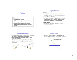
1. Angular Kinetics
Torque Kinetics
• study of the relationship between the forces
acting on a system and the motion of the system
Angular Motion (Rotation)
Objectives: • All points in an object or system move in a circle
• Define angular kinetics about a single axis of rotation. All points move
• Define and learn to compute moment through the same angle in the same time
arms, torque, and resultant torques Linear Kinetics
• Introduction to resultant joint torques, • The kinetics of particles, objects, or systems
anatomical torque descriptions, and force undergoing rotation
couples
Torque (or Moment) Line of Action
• A measure of the extent to which a force will cause • The line of action of a force is the imaginary line
an object to rotate about a specific axis that extends from the force vector in both directions
• A net force applied through the center of mass
produces translation
• A net force applied away from the center of mass line of action of F
(i.e. an eccentric force) produces both translation
and rotation
F
F F
1
2. Moment Arm Computing a Moment Arm
• Shortest distance from a force’s line of action to the • Need to know:
axis of rotation – distance (d) from axis of rotation to point at which
• Moment arm is always perpendicular to the line of force is applied
action and passes through the axis of rotation – angle (θ) at which force is applied
• Use trigonometry to compute moment arm (d⊥)
line of action of F
d⊥ = d sin θ
90°
moment arm
of F F
axis of rotation F
θ
axis of rotation d
Moment Arm Examples Computing Torque
• Torque has:
axis of rotation d⊥ = d
d – a magnitude
– a direction (+ or –)
θ – a specific axis of rotation
d⊥= d sin θ F F • The magnitude of the torque (T) produced by a force
is the product of the force’s magnitude (F) times the
force’s moment arm (d⊥):
axis of T = F d⊥
T = F d⊥ rotation
d⊥ = d sin θ d⊥ = 0
θ F
• Units: F
d F d – English: foot-pounds (ft-lb) d⊥
– SI : Newton-meters (Nm)
2
3. Direction of a Torque Example Problem #1
• Positive torque : acts counterclockwise about the Shown below are 4 muscles acting across a joint.
axis of rotation. Which muscles have the largest and smallest
• Negative torque : acts clockwise about the axis force? moment arm? torque magnitude?
• Determine direction using the right hand rule: 3 100 N
2 100 N
– Place right hand on force vector, fingers towards
arrow tip joint
50°
– Curl fingers around axis of rotation 20°
– Torque acts in direction that fingers are curled 60°
1 150 N 0.01 m
T>0 T<0 limb segment
0.02 m
90°
axis of F F 0.04 m
rotation 4 35 N
Torque Composition Resultant Joint Torque
• Process of determining a single resultant (or net)
torque from two or more torques. • The effects of all forces acting about a joint can be
• Performed by adding the torques together, taking the duplicated exactly by the combination of:
sign (direction) of the torque into account – A resultant joint force acting at the joint center
• Resultant torque has same effect on rotation as the – A resultant joint torque acting about the axis of
individual torques acting together rotation through the joint center
T3 T net = |T 1| – |T 2| + |T 3| • Resultant joint force is the vector composition of all
F3
forces acting across a joint.
T1 • Resultant joint torque is the composition of the
axis of torques produced about the joint axis by these forces.
rotation
T2 • Note: Forces that do not act across the joint (e.g.
F1 F2 weight) are not included in the resultant joint force or
torque.
Note: |T| = magnitude of torque T (≥ 0)
3
4. Example Use of Resultant Joint Torque
• Typically, joint contact force, muscle forces, ligament
Fcontact forces, etc. cannot be determined individually
Tresultant
Fresultant
• We can compute resultant joint forces and torques
Facl
d ⊥acl based on data measured external to the body
knee joint center
• Except near the limits of the anatomical range of
d ⊥quads Fquads Fquads
Fcontact motion, the main contributors to the resultant joint
d ⊥hams
Fhams torque are the muscles
tibia • The resultant joint torque provides a simplified picture
Facl
Fhams of which muscle groups are most active about a joint
Tresultant = (Fquads d⊥quads) + (F acl d⊥acl) – (Fhams d⊥hams)
Example Problem #2 Force Couple
Shown is a forearm with 2 elbow flexors and 1 • For pure rotation about the center of mass, the center
elbow extensor. Find the resultant joint torque for of mass must remain stationary from Newton’s 1st
the 3 combinations of forces shown in the table: law, the net force on the object must equal zero
• Force couple : Two forces of equal magnitude,
Ft 0 0 32
Ft Fcontact Fbi applied in opposite directions. Produce pure rotation
Fbr
about the center of mass.
Fcontact 8 3.2 46.4
T = F (d⊥1 + d ⊥2 )
30° F
Fbi 16 10 20
0.025 m 0.05 m d⊥2
0.10 m
W=8N d⊥1
Fbr 0 2.4 4.8 ΣF=0
0.25 m F
RJT
Force Couple Net Effect
4
5. Anatomical Torques
• Positive & negative torques depend on frame of
reference chosen:
y y
Fquad Fquad
knee knee
T>0 T<0
x x
• To avoid this problem, joint torques are typically
described by the joint motion that would occur if the
segment moved in the direction of the torque
(e.g. Fquad produces a knee extension torque)
5