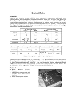
SlideShare a Scribd company logo
1 of 8
Rotational Motion
Introduction
There are many similarities between straight-line motion (translation) in one dimension and angular motion
(rotation) of a rigid object that is spinning around some rotation axis. In both cases, the position of the object can be
described by a single variable, and its speed and acceleration can be obtained from time derivatives of that variable.
Table 1 compares parameters used to describe both translational and rotational motion. Since there are so many
common parameters in translational and rotational motion, the descriptor “linear” or “angular” is typically inserted in
front of quantities like position, speed, velocity, acceleration, and momentum to specify whether we are referring to
translational or rotational motion, respectively.

                                      Translational Motion                                 Rotational Motion
                                    Symbol             Units                           Symbol              Units
       Position                       x                 (m)                              !                 (rad)
                                            dx                                                 d#
        Speed                          v=                      (m/s)                       =                        (rad/s)
                                            dt                                                 dt

                                       dv d 2 x                                           d# d 2
     Acceleration                 a=     =                     (m/s2)                 =      = 2                   (rad/s2)
                       !               dt dt 2                               !            dt  dt
      Momentum                         p = mv                 (kg! /s)
                                                                 m                        L=I                      (kgm2/s)

                  !                                                      !
    Source of         Parameter               Symbol            Units            Parameter           Symbol             Units
                       !                                                     !
                                                       dp                                                     dL
 Acceleration              Force            F = ma =             (N)              Torque             = I# =             (Nm)
                                                       dt                                                     dt
                                                                                 Moment of
     Inertia               Mass                  m               (kg)
                                                                                  Inertia               ( )
                                                                                                    I = k mr 2         (kgm2)
                            !                                                        !
                                   Table 1: Comparison of Translational and Rotational Motion in One Dimension
                                                                  r     !
                                                                        r
For translational motion, Newton’s second law is expressed as F = ma . The applied force is linearly proportional to
the resulting acceleration, and the proportionality constant r the mass. Newton’s second law can also be expressed
                                                        r    is
for objects undergoing angular motion - in this case, = I# . The applied torque generates an angular acceleration,
and the two quantities are linearly proportional with a proportionality constant equal to the moment of inertia. This
                                                      !
lab is designed to explore the generation of torques and the rotational motion that follows.

Equipment                                              !
•    PASCO       Rotational     Dynamics
     Apparatus
•    Various Inertia Demonstration Tools
     (wrenches, meter sticks w/masses
     attached)
•    Digital Balance (shared by class)


                                                                         1
Rotational Motion                                                                                  Physics 117/197/211


    Background
    In one-dimensional linear (translational) motion, when a force acts on an object, the object undergoes a linear
    acceleration, and, thus, the linear velocity of the object changes. In rotational motion, forces can also generate an
    angular acceleration, but it is not just the force that causes the acceleration, but also where that force is applied.

    A simple experiment demonstrates this point. If you try to tighten and loosen a bolt using wrenches of two different
    lengths, you will quickly convince yourself that the same force applied to the shorter wrench has less effect on the
    bolt than the longer wrench. The same force applied a greater distance from the axis of rotation thus produces a
    larger result. This leads us to an important principle, that of torque. It is torque that is responsible for generating
    angular acceleration.
                                      r
    In the most general form, torque ( ) is expressed as the cross r
                                                                   product of the moment arm and the applied force
                                                           r r
                                                             =r#F
            r                                                                                  r
    where r is the moment !arm, measured from the rotation axis to the point where the force, F , is applied (See Figure
    1). The units of torque are Newton-meters (N-m).
                                                !
    The magnitude of the torque is expressed as
!                                                                                         !
                                                              = rF sin #

    where ! is the angle between the moment arm and force vectors when the tails of the vectors are together. Only the
    component of the force perpendicular to the moment arm generates a torque.
                                              !


                                               Figure 1: Physical Description of Torque
                                                              r                                         r
    For the special case shown in Figure 1, where the force, F , is at a right angle to the moment arm, r , the magnitude
                   r
    of the torque, , is simply the product of the force and moment arm magnitudes, = Fr.

    In linear motion, forces generate changes in linear velocity, but the mass of the object resists this change. For a given
                                                    !                                            !
    applied force, the larger the mass, the smaller the resulting linear acceleration. There are similar analogs for
         !
    rotational motion. Torque causes a change in angular velocity, and the moment of inertia resists the change.

    The moment of inertia, I, of an object or a system of objects depends both on the mass of the object(s) as well as how
    the mass is distributed relative to a rotation axis. Objects with large moments of inertia strongly resist changes in
    their angular motion while those with small moments of inertia are less resistant to change.

    To illustrate these concepts, consider the following scenario (you can try this yourself when you come to your lab
    section). You have two identical meter sticks each of which have a total of 400 g of mass attached to it: in one case
    (Figure 2, left), 200 g masses are attached to each end of the meter stick; In the other case (Figure 2, right), all 400 g
    of mass are placed at the center of the meter stick. Holding the meter sticks at their midpoints and rotating, you will
    find that it is much easier to rotate the meter stick with all the mass at the center than the one with masses at both
    ends.


                                                                  2
Rotational Motion                                                                                    Physics 117/197/211


                                 Figure 2: Mass Distribution and Its Effects on Moments of Inertia

Even though the total mass attached to each stick is the same, the ease with which you can start the meter sticks
rotating varies. This is because the meter stick with masses on its ends has a larger moment of inertia than the one
with all the mass at its midpoint, and in rotational motion, the moment of inertia is what resists changes in angular
motion.

As the meter stick example illustrates, there is more to the moment of inertia than simply mass, which is what resists
changes in translational motion. Moment of inertia additionally cares about where the mass is located relative to a
rotation axis. The moment of inertia of a given mass will increase the farther the mass is from the rotation axis. This
is why the meter stick with masses on the ends is harder to rotate. It has a larger moment of inertia.

Objects with uniform density have moments of inertia of the form

                                                                ( )
                                                          I = k mr 2

where k is a constant specific to the geometry of the object and the location of the rotation axis, m is the mass, and r
describes certain dimensions of the object (not necessarily a radius). Dimensional analysis of the moment of inertia
                                             !
expression tells us that it has units of kg-m2.

Procedure: Angular Acceleration from Angular Velocity
In this first study, you will measure the angular acceleration of a rotating steel disk using two independent
techniques. The first approach uses measurements of the angular velocity, # , as a function of time to determine the
angular acceleration, . The second method determines from calculations of the moment of inertia of the steel
disk and the torque applied to it by a falling mass. The PASCO Rotational Dynamics Apparatus, which will be
employed in these rotational motion studies, is sketched in Figure 3.

The experimental apparatus is designed for two discs to be placed on the rotation axis simultaneously. They can,
however, either rotate together as a rigid object or independent of one another. For this lab, we will only be using
the upper disc in our rotation studies. The bottom disc should remain fixed to the base of the apparatus.

The hanging mass (mh = 25 g), which generates tension in the string, runs over a low friction air bearing and is
wrapped around the spool (rs = 0.5 in). When the hanging mass is released, the disc-spool system begins to rotate
together due to the torque applied to the spool by the tension in the string.

The angular speed of either the top or bottom disc is indirectly obtained from a digital display that works by using
optical readers to count the number of black bars on the side of the disc that pass by in one second. There are 200
black bars around the circumference of each disc. The display is updated once every 2 seconds. A switch allows the
user to monitor the speed of either the top or bottom disc.


                                                                3
Rotational Motion                                                                                Physics 117/197/211


                                             Figure 3: Experimental Apparatus

In this study, you will confirm the relationship between torque and angular acceleration, = I . Just as linear
acceleration causes a change in linear velocity, so also does angular acceleration, , generate a change in angular
velocity where
                                                      = 0+ # t

when the angular acceleration is constant. Note: since we are only studying rotations in one dimension, we have
eliminated the vector notation on the torque and the angular velocity.
                                          !
By measuring the angular velocity of the rotating disc as a function of time, you will be able to determine its angular
acceleration from a plot of your experimental data.

    •    Place BOTH steel discs on the rotation axis, and make certain that the bottom disc is resting firmly on the
         bottom plate, i.e., not floating.
    •    Using the hollow, black cap screw, secure the thread anchor washer and small spool to the hole in the center
         of the top disc.
    •    The thread anchor washer fits into the recess of the spool, and the cap screw goes through the hole in the
         washer and spool and into the threaded hole in the top disc.
    •    The string should fit through the slot of the spool, run over the groove in the cylinder air bearing and
         suspend the hanging 25 g mass beyond the edge of the table (See Figure 3).
    •    Insert the drop pin into the hole of the cap screw to float the top disc.
    •    With the compressed air turned on, rotate the upper disc to wind the thread around the spool until the top of
         the hanging mass is level with the top of the base.
    •    Hold the top disc stationary for a moment, and then release it, being careful not to give it any initial
         velocity. The hanging mass will exert a torque on the disc as it falls, accelerating the disc.
    •    Set the switch on the digital display to TOP to display the number of black bars on the top disc passing the
         optical reader each second.
    •    As soon as the top disc is released, begin recording data from the readout of the digital display (Note: the
         digital display updates every 2 seconds).
    •    Get at least five data points between the time the disc is released and the time the hanging mass reaches its
         lowest point.
    •    Try this a couple of times before recording your actual measurements.
    •    For your analysis of these measurements, do not use the first and last data points for reasons discussed in
         the following Equipment Note.
    •    Convert your measurements to angular velocity, and plot # as a function of time.
    •    Determine the angular acceleration, , of the disc from the best fit line to your data.


                                                            4
Rotational Motion                                                                                   Physics 117/197/211


Equipment Note: The optical reader counts the number of bars that pass the sensor in a one-second
interval. It then displays that value for two seconds. During the first second of this two second interval, the
counter is idle. During the next second, the counter is taking readings for the next value to be displayed.
This sequence repeats continuously, so there is no way for you to start the timing sequence for your data run
at the instant you release the disc. Thus, if you happen to release the disc during a second when the sensor is
counting, the first reading will be erroneously low. If you are luckier and release the disc during an idle
second, the first reading will be valid. However, since there is no way to know which scenario applies to
your first measurement, the safest thing to do is to not use the first reading. For your final measurement, the
hanging mass may have reached its lowest point and begun rising during the time that the last measurement
is being accumulated, so as a precautionary measure, we will also choose to not use the last measurement.

Determining Angular Acceleration Using Moments of Inertia
The angular acceleration of a rotating object can also be determined from the ratio of the applied torque to the
object’s moment of inertia,
                                                          #
                                                        =
                                                          I

In this study, we’ll calculate the angular acceleration of the disc in this fashion, and compare the result to the value
of we obtained from angular velocity measurements.
                                              !
To determine the torque applied to the spool-disc system, we need to know the force that generates the torque and
where it is applied. It is the tension in the string attached to the hanging mass that causes a torque to be applied to the
spool-disc system.

    •    Draw a free body diagram, illustrating all the forces acting on the 25 g hanging mass while it is falling
    •    Find an algebraic expression for the tension in the string in terms of the hanging mass, mh, the acceleration
         of gravity, g, and the linear acceleration of the hanging mass, a.
    •    Rewrite the equation from the previous step in terms of the angular acceleration of the spool-disc system, ,
         rather than the linear acceleration of the hanging mass, and solve for the tension.
    •    For some experimental conditions, the tension in the string is approximately equal to the weight of the
         hanging mass. Determine whether this approximation is valid for your experimental conditions. Justify your
         conclusion with supporting evidence from your earlier measurement of . Using your expression for the
         tension in the string, compute the torque applied to the spool-disc system.

To compute the angular acceleration, we also need to determine the moment of inertia of our rotating system, which
includes both the steel disc and the spool (Figure 4). The moment of inertia of the system is the sum of the
individual moments of inertia. Both the disc and the spool are cylindrical in shape with a hollowed out portion at
their centers. The moment of inertia for such a shape with the rotation axis about the symmetry axis of the cylinder
is
                                                     1
                                                            (
                                                  I = m r12 + r2 2
                                                     2
                                                                     )
where m is the mass of the hollowed out cylinder, r1 is the inner radius, and r2 is the outer radius of the cylinder.
                                          !
Because both the mass and radii of the spool are substantially smaller than those of the steel disc, the moment of
inertia of the spool-disc system can be approximated by the moment of inertia of the steel disc alone. The mass of
the steel disc is etched on its upper surface, and the dimensions of the disc are provided in Figure 4. Notice that the
inner radius of the steel disc is not constant throughout the entire thickness of the disc.


                                                            5
Rotational Motion                                                                                Physics 117/197/211


                                          Figure 4: Dimensions for the Steel Disc

    •   Compute an approximate moment of inertia for the steel disc, justifying any approximations you make.
    •   Compute an approximate value for the angular acceleration of the disc from the ratio of the torque applied
        to the moment of inertia.
    •   Compare this result with the value of ! derived from the velocity measurements.

Effect of Mass Distribution on Moment of Inertia
This experiment investigates how the moment of inertia of a system changes when its mass is redistributed about the
rotation axis. You will measure the angular acceleration, , that results from the application of a constant torque, ,
as the moment of inertia of the system is systematically varied by moving masses away from the axis of rotation.

    •   Secure the spool, thread anchor washer, and the variable radius mass unit to the hole in the center of the top
        disc as shown in Figure 5.
    •   The valve for the bottom disc should be set so that it does not "float".
    •   The 200-gram sliding masses can be moved by loosening the set screws.
    •   Start with the 200 g masses touching the center hub (here, r = 2.967 cm…see Figure 6).
    •   As in the previous experiment, rotate the disc to wind up the thread until the top of the falling mass is at the
        top of the base.


                                                            6
Rotational Motion                                                                                             Physics 117/197/211


                                   Figure 5: Mass Distribution System with Experimental Apparatus

    •    Hold the top disc stationary, and then release the hanging mass and record the output of the digital display
         every 2 seconds.
    •    Convert the data to angular velocity, plot # as a function of time, and determine the angular acceleration, ,
         from the best-fit line to your experimental data as you did before.
    •    From this and the known torque, compute the moment of inertia of this complex rotating system.
    •    Repeat this experiment five times, increasing the radial distance of both 200 g masses by one centimeter
         each time. Use the gauge shown in Figure 7 to re-position the masses. Be sure to set both masses to the
         same radius prior to each trial.
    •    Create a plot of the moment of inertia (I) as a function of r2, where r is the distance from the rotation axis to
         the center of the 200 g masses.


              Figure 6: Mass Distribution System                                 Figure 7: Adjusting the Mass Distribution

The whole rotating system includes the top disc, the spool, the center hub, and the supporting rods as well as the
sliding masses. The moment of inertia of this complex system is equivalent to the sum of the moments of inertia of
each part. Because much of the system mass is stationary from trial to trial, that contribution to the total moment of
inertia should be constant as we move each of the 200-gram masses away from the rotation axis. Thus, if we plot the
total moment of inertia of the system, I, as a function of r2, we should obtain a plot of the form

                                                          I = I 0 + Mr 2


Explain what the terms I0 and M represent in your experiment.
                                         !


                                                                 7
Rotational Motion                                                                                Physics 117/197/211


Concluding Questions
When responding to the questions/exercises below, your responses need to be complete and coherent. Full credit will
only be awarded for correct answers that are accompanied by an explanation and/or justification. Include enough of
the question/exercise in your response that it is clear to your teaching assistant to which problem you are responding.

    1.   If the rotating metal disk used in the first part of the rotational motion lab was replaced by one of the same
         volume but of half the density, explain what happens to the moment of inertia and the angular acceleration
         of the disk when the experiment is performed.
    2.   You want to reduce the tendency of a solid cylinder to start rotating when a torque is applied to it. Your
         options are to either double the mass of the cylinder, halve the mass, double the radius of the cylinder, or
         halve the radius. Which of these four options will be most effective at reducing the tendency of the cylinder
         to start rotating? Justify your answer.
    3.   In order to precisely determine the tension in the string attached to the spool and the hanging mass, you
         need to know the linear acceleration of the hanging mass or the angular acceleration of the disc-spool
         system. If the tension is approximated by the weight of the hanging mass, do you over- or under-estimate
         the torque on the disc-spool system? Explain.
    4.   Derive an algebraic expression for the absolute uncertainty of the moment of inertia for a hollowed out
         cylinder where
                                                         1
                                                          (        )
                                                     I = m r12 + r2 2
                                                         2

         Your answer should include the variables m, r1, and r2, as well as the uncertainties associated with each of
         these parameters (% % 1, % 2).
                            m, r r
                                      !


                                                          8

More Related Content

What's hot

ROTATION OF RIGID BODIES
ROTATION OF RIGID BODIESROTATION OF RIGID BODIES
ROTATION OF RIGID BODIESshahzadebaujiti
 
Rotational dynamics as per class 12 Maharashtra State Board syllabus
Rotational dynamics as per class 12 Maharashtra State Board syllabusRotational dynamics as per class 12 Maharashtra State Board syllabus
Rotational dynamics as per class 12 Maharashtra State Board syllabusRutticka Kedare
 
Rotational motion pt2
Rotational motion pt2Rotational motion pt2
Rotational motion pt2stephm32
 
How to Prepare Rotational Motion (Physics) for JEE Main
How to Prepare Rotational Motion (Physics) for JEE MainHow to Prepare Rotational Motion (Physics) for JEE Main
How to Prepare Rotational Motion (Physics) for JEE MainEdnexa
 
Rotational dynamics ppt3
Rotational dynamics ppt3Rotational dynamics ppt3
Rotational dynamics ppt3Rutticka Kedare
 
Ch 8 Rotational Kinematics
Ch 8 Rotational KinematicsCh 8 Rotational Kinematics
Ch 8 Rotational KinematicsScott Thomas
 
Chapter13 rigid body rotation
Chapter13 rigid body rotationChapter13 rigid body rotation
Chapter13 rigid body rotationDarwin Quinsaat
 
PHYSICS - Rotational dynamics (MAHARASHTRA STATE BOARD)
PHYSICS - Rotational dynamics (MAHARASHTRA STATE BOARD)PHYSICS - Rotational dynamics (MAHARASHTRA STATE BOARD)
PHYSICS - Rotational dynamics (MAHARASHTRA STATE BOARD)Pooja M
 
5 - Circular motion
5 - Circular motion5 - Circular motion
5 - Circular motionguest924dbe
 
Free Fall & Projectiles 1
Free Fall & Projectiles 1Free Fall & Projectiles 1
Free Fall & Projectiles 1zglazenburg
 
Chapter10 -circular motion
Chapter10 -circular motionChapter10 -circular motion
Chapter10 -circular motionsashrilisdi
 
13. kinematics of rigid bodies
13. kinematics of rigid bodies13. kinematics of rigid bodies
13. kinematics of rigid bodiesEkeeda
 
Chapter 12 rotational motion
Chapter 12 rotational motionChapter 12 rotational motion
Chapter 12 rotational motionLisa Stack
 

What's hot (20)

ROTATION OF RIGID BODIES
ROTATION OF RIGID BODIESROTATION OF RIGID BODIES
ROTATION OF RIGID BODIES
 
Rotational dynamics as per class 12 Maharashtra State Board syllabus
Rotational dynamics as per class 12 Maharashtra State Board syllabusRotational dynamics as per class 12 Maharashtra State Board syllabus
Rotational dynamics as per class 12 Maharashtra State Board syllabus
 
Rotational motion pt2
Rotational motion pt2Rotational motion pt2
Rotational motion pt2
 
AP Physics C Rotational Motion
AP Physics C Rotational MotionAP Physics C Rotational Motion
AP Physics C Rotational Motion
 
Rotational motion
Rotational motionRotational motion
Rotational motion
 
How to Prepare Rotational Motion (Physics) for JEE Main
How to Prepare Rotational Motion (Physics) for JEE MainHow to Prepare Rotational Motion (Physics) for JEE Main
How to Prepare Rotational Motion (Physics) for JEE Main
 
AP Physics C Rotational Motion II
AP  Physics C Rotational Motion IIAP  Physics C Rotational Motion II
AP Physics C Rotational Motion II
 
Rotational dynamics ppt3
Rotational dynamics ppt3Rotational dynamics ppt3
Rotational dynamics ppt3
 
Ch 8 Rotational Kinematics
Ch 8 Rotational KinematicsCh 8 Rotational Kinematics
Ch 8 Rotational Kinematics
 
Chapter13 rigid body rotation
Chapter13 rigid body rotationChapter13 rigid body rotation
Chapter13 rigid body rotation
 
Linear and angular momentum
Linear and angular momentum Linear and angular momentum
Linear and angular momentum
 
3 angular motion
3 angular motion3 angular motion
3 angular motion
 
PHYSICS - Rotational dynamics (MAHARASHTRA STATE BOARD)
PHYSICS - Rotational dynamics (MAHARASHTRA STATE BOARD)PHYSICS - Rotational dynamics (MAHARASHTRA STATE BOARD)
PHYSICS - Rotational dynamics (MAHARASHTRA STATE BOARD)
 
Circular Motion
Circular MotionCircular Motion
Circular Motion
 
5 - Circular motion
5 - Circular motion5 - Circular motion
5 - Circular motion
 
Free Fall & Projectiles 1
Free Fall & Projectiles 1Free Fall & Projectiles 1
Free Fall & Projectiles 1
 
Chapter10 -circular motion
Chapter10 -circular motionChapter10 -circular motion
Chapter10 -circular motion
 
13. kinematics of rigid bodies
13. kinematics of rigid bodies13. kinematics of rigid bodies
13. kinematics of rigid bodies
 
Uniform Circular Motion
Uniform Circular MotionUniform Circular Motion
Uniform Circular Motion
 
Chapter 12 rotational motion
Chapter 12 rotational motionChapter 12 rotational motion
Chapter 12 rotational motion
 

Viewers also liked

Viewers also liked (8)

Science Presentation on Motion
Science Presentation on MotionScience Presentation on Motion
Science Presentation on Motion
 
What is motion and its types
What is motion and its typesWhat is motion and its types
What is motion and its types
 
Rotational motion
Rotational motionRotational motion
Rotational motion
 
What Is Motion
What Is MotionWhat Is Motion
What Is Motion
 
Motion, speed and velocity
Motion, speed and velocityMotion, speed and velocity
Motion, speed and velocity
 
MOTION Class IX PowerPoint Presentation
MOTION Class IX PowerPoint Presentation MOTION Class IX PowerPoint Presentation
MOTION Class IX PowerPoint Presentation
 
Types of motion
Types of motion Types of motion
Types of motion
 
Motion and Types of motion
Motion and Types of motionMotion and Types of motion
Motion and Types of motion
 

Similar to Rotational motion

Motion in a circle
Motion in a circleMotion in a circle
Motion in a circleCatherine He
 
Purdue Prelecture Content IMPACT
Purdue Prelecture Content IMPACTPurdue Prelecture Content IMPACT
Purdue Prelecture Content IMPACTdoylejackd
 
O level physics formula sheet
O level physics formula sheetO level physics formula sheet
O level physics formula sheetsrhyder21
 
Mechanical system
Mechanical systemMechanical system
Mechanical systemAliAhssan
 
Engineering science lesson 1
Engineering science lesson 1Engineering science lesson 1
Engineering science lesson 1Shahid Aaqil
 
Engineering science lesson 1
Engineering science lesson 1Engineering science lesson 1
Engineering science lesson 1Shahid Aaqil
 
LO: Harmonic Waves
LO: Harmonic WavesLO: Harmonic Waves
LO: Harmonic Wavesnatnahirney
 
Spm physics-formula-list-form4
Spm physics-formula-list-form4Spm physics-formula-list-form4
Spm physics-formula-list-form4Salty Tay Xian
 
Physics formula list
Physics formula listPhysics formula list
Physics formula listJSlinkyNY
 
Spm physics-formula-list-form4
Spm physics-formula-list-form4Spm physics-formula-list-form4
Spm physics-formula-list-form4Nur Harleesa
 
Physics formulas list
Physics formulas listPhysics formulas list
Physics formulas listhannagrauser1
 
Cm 1a circular motion mathematical description (shared)
Cm 1a circular motion   mathematical description (shared)Cm 1a circular motion   mathematical description (shared)
Cm 1a circular motion mathematical description (shared)LThistlewood
 
4831603 physics-formula-list-form-4
4831603 physics-formula-list-form-44831603 physics-formula-list-form-4
4831603 physics-formula-list-form-4Harsh Vardhan
 
4831603 physics-formula-list-form-4
4831603 physics-formula-list-form-44831603 physics-formula-list-form-4
4831603 physics-formula-list-form-4hongtee82
 
X2 t06 03 circular motion (2012)
X2 t06 03 circular motion (2012)X2 t06 03 circular motion (2012)
X2 t06 03 circular motion (2012)Nigel Simmons
 

Similar to Rotational motion (20)

Motion in a circle
Motion in a circleMotion in a circle
Motion in a circle
 
Lecture 16
Lecture 16Lecture 16
Lecture 16
 
Purdue Prelecture Content IMPACT
Purdue Prelecture Content IMPACTPurdue Prelecture Content IMPACT
Purdue Prelecture Content IMPACT
 
v2chap2.pdf
v2chap2.pdfv2chap2.pdf
v2chap2.pdf
 
O level physics formula sheet
O level physics formula sheetO level physics formula sheet
O level physics formula sheet
 
Mechanical system
Mechanical systemMechanical system
Mechanical system
 
Physics formulae
Physics formulaePhysics formulae
Physics formulae
 
Lec04
Lec04Lec04
Lec04
 
Ap review total
Ap review totalAp review total
Ap review total
 
Engineering science lesson 1
Engineering science lesson 1Engineering science lesson 1
Engineering science lesson 1
 
Engineering science lesson 1
Engineering science lesson 1Engineering science lesson 1
Engineering science lesson 1
 
LO: Harmonic Waves
LO: Harmonic WavesLO: Harmonic Waves
LO: Harmonic Waves
 
Spm physics-formula-list-form4
Spm physics-formula-list-form4Spm physics-formula-list-form4
Spm physics-formula-list-form4
 
Physics formula list
Physics formula listPhysics formula list
Physics formula list
 
Spm physics-formula-list-form4
Spm physics-formula-list-form4Spm physics-formula-list-form4
Spm physics-formula-list-form4
 
Physics formulas list
Physics formulas listPhysics formulas list
Physics formulas list
 
Cm 1a circular motion mathematical description (shared)
Cm 1a circular motion   mathematical description (shared)Cm 1a circular motion   mathematical description (shared)
Cm 1a circular motion mathematical description (shared)
 
4831603 physics-formula-list-form-4
4831603 physics-formula-list-form-44831603 physics-formula-list-form-4
4831603 physics-formula-list-form-4
 
4831603 physics-formula-list-form-4
4831603 physics-formula-list-form-44831603 physics-formula-list-form-4
4831603 physics-formula-list-form-4
 
X2 t06 03 circular motion (2012)
X2 t06 03 circular motion (2012)X2 t06 03 circular motion (2012)
X2 t06 03 circular motion (2012)
 

Rotational motion

  • 1. Rotational Motion Introduction There are many similarities between straight-line motion (translation) in one dimension and angular motion (rotation) of a rigid object that is spinning around some rotation axis. In both cases, the position of the object can be described by a single variable, and its speed and acceleration can be obtained from time derivatives of that variable. Table 1 compares parameters used to describe both translational and rotational motion. Since there are so many common parameters in translational and rotational motion, the descriptor “linear” or “angular” is typically inserted in front of quantities like position, speed, velocity, acceleration, and momentum to specify whether we are referring to translational or rotational motion, respectively. Translational Motion Rotational Motion Symbol Units Symbol Units Position x (m) ! (rad) dx d# Speed v= (m/s) = (rad/s) dt dt dv d 2 x d# d 2 Acceleration a= = (m/s2) = = 2 (rad/s2) ! dt dt 2 ! dt dt Momentum p = mv (kg! /s) m L=I (kgm2/s) ! ! Source of Parameter Symbol Units Parameter Symbol Units ! ! dp dL Acceleration Force F = ma = (N) Torque = I# = (Nm) dt dt Moment of Inertia Mass m (kg) Inertia ( ) I = k mr 2 (kgm2) ! ! Table 1: Comparison of Translational and Rotational Motion in One Dimension r ! r For translational motion, Newton’s second law is expressed as F = ma . The applied force is linearly proportional to the resulting acceleration, and the proportionality constant r the mass. Newton’s second law can also be expressed r is for objects undergoing angular motion - in this case, = I# . The applied torque generates an angular acceleration, and the two quantities are linearly proportional with a proportionality constant equal to the moment of inertia. This ! lab is designed to explore the generation of torques and the rotational motion that follows. Equipment ! • PASCO Rotational Dynamics Apparatus • Various Inertia Demonstration Tools (wrenches, meter sticks w/masses attached) • Digital Balance (shared by class) 1
  • 2. Rotational Motion Physics 117/197/211 Background In one-dimensional linear (translational) motion, when a force acts on an object, the object undergoes a linear acceleration, and, thus, the linear velocity of the object changes. In rotational motion, forces can also generate an angular acceleration, but it is not just the force that causes the acceleration, but also where that force is applied. A simple experiment demonstrates this point. If you try to tighten and loosen a bolt using wrenches of two different lengths, you will quickly convince yourself that the same force applied to the shorter wrench has less effect on the bolt than the longer wrench. The same force applied a greater distance from the axis of rotation thus produces a larger result. This leads us to an important principle, that of torque. It is torque that is responsible for generating angular acceleration. r In the most general form, torque ( ) is expressed as the cross r product of the moment arm and the applied force r r =r#F r r where r is the moment !arm, measured from the rotation axis to the point where the force, F , is applied (See Figure 1). The units of torque are Newton-meters (N-m). ! The magnitude of the torque is expressed as ! ! = rF sin # where ! is the angle between the moment arm and force vectors when the tails of the vectors are together. Only the component of the force perpendicular to the moment arm generates a torque. ! Figure 1: Physical Description of Torque r r For the special case shown in Figure 1, where the force, F , is at a right angle to the moment arm, r , the magnitude r of the torque, , is simply the product of the force and moment arm magnitudes, = Fr. In linear motion, forces generate changes in linear velocity, but the mass of the object resists this change. For a given ! ! applied force, the larger the mass, the smaller the resulting linear acceleration. There are similar analogs for ! rotational motion. Torque causes a change in angular velocity, and the moment of inertia resists the change. The moment of inertia, I, of an object or a system of objects depends both on the mass of the object(s) as well as how the mass is distributed relative to a rotation axis. Objects with large moments of inertia strongly resist changes in their angular motion while those with small moments of inertia are less resistant to change. To illustrate these concepts, consider the following scenario (you can try this yourself when you come to your lab section). You have two identical meter sticks each of which have a total of 400 g of mass attached to it: in one case (Figure 2, left), 200 g masses are attached to each end of the meter stick; In the other case (Figure 2, right), all 400 g of mass are placed at the center of the meter stick. Holding the meter sticks at their midpoints and rotating, you will find that it is much easier to rotate the meter stick with all the mass at the center than the one with masses at both ends. 2
  • 3. Rotational Motion Physics 117/197/211 Figure 2: Mass Distribution and Its Effects on Moments of Inertia Even though the total mass attached to each stick is the same, the ease with which you can start the meter sticks rotating varies. This is because the meter stick with masses on its ends has a larger moment of inertia than the one with all the mass at its midpoint, and in rotational motion, the moment of inertia is what resists changes in angular motion. As the meter stick example illustrates, there is more to the moment of inertia than simply mass, which is what resists changes in translational motion. Moment of inertia additionally cares about where the mass is located relative to a rotation axis. The moment of inertia of a given mass will increase the farther the mass is from the rotation axis. This is why the meter stick with masses on the ends is harder to rotate. It has a larger moment of inertia. Objects with uniform density have moments of inertia of the form ( ) I = k mr 2 where k is a constant specific to the geometry of the object and the location of the rotation axis, m is the mass, and r describes certain dimensions of the object (not necessarily a radius). Dimensional analysis of the moment of inertia ! expression tells us that it has units of kg-m2. Procedure: Angular Acceleration from Angular Velocity In this first study, you will measure the angular acceleration of a rotating steel disk using two independent techniques. The first approach uses measurements of the angular velocity, # , as a function of time to determine the angular acceleration, . The second method determines from calculations of the moment of inertia of the steel disk and the torque applied to it by a falling mass. The PASCO Rotational Dynamics Apparatus, which will be employed in these rotational motion studies, is sketched in Figure 3. The experimental apparatus is designed for two discs to be placed on the rotation axis simultaneously. They can, however, either rotate together as a rigid object or independent of one another. For this lab, we will only be using the upper disc in our rotation studies. The bottom disc should remain fixed to the base of the apparatus. The hanging mass (mh = 25 g), which generates tension in the string, runs over a low friction air bearing and is wrapped around the spool (rs = 0.5 in). When the hanging mass is released, the disc-spool system begins to rotate together due to the torque applied to the spool by the tension in the string. The angular speed of either the top or bottom disc is indirectly obtained from a digital display that works by using optical readers to count the number of black bars on the side of the disc that pass by in one second. There are 200 black bars around the circumference of each disc. The display is updated once every 2 seconds. A switch allows the user to monitor the speed of either the top or bottom disc. 3
  • 4. Rotational Motion Physics 117/197/211 Figure 3: Experimental Apparatus In this study, you will confirm the relationship between torque and angular acceleration, = I . Just as linear acceleration causes a change in linear velocity, so also does angular acceleration, , generate a change in angular velocity where = 0+ # t when the angular acceleration is constant. Note: since we are only studying rotations in one dimension, we have eliminated the vector notation on the torque and the angular velocity. ! By measuring the angular velocity of the rotating disc as a function of time, you will be able to determine its angular acceleration from a plot of your experimental data. • Place BOTH steel discs on the rotation axis, and make certain that the bottom disc is resting firmly on the bottom plate, i.e., not floating. • Using the hollow, black cap screw, secure the thread anchor washer and small spool to the hole in the center of the top disc. • The thread anchor washer fits into the recess of the spool, and the cap screw goes through the hole in the washer and spool and into the threaded hole in the top disc. • The string should fit through the slot of the spool, run over the groove in the cylinder air bearing and suspend the hanging 25 g mass beyond the edge of the table (See Figure 3). • Insert the drop pin into the hole of the cap screw to float the top disc. • With the compressed air turned on, rotate the upper disc to wind the thread around the spool until the top of the hanging mass is level with the top of the base. • Hold the top disc stationary for a moment, and then release it, being careful not to give it any initial velocity. The hanging mass will exert a torque on the disc as it falls, accelerating the disc. • Set the switch on the digital display to TOP to display the number of black bars on the top disc passing the optical reader each second. • As soon as the top disc is released, begin recording data from the readout of the digital display (Note: the digital display updates every 2 seconds). • Get at least five data points between the time the disc is released and the time the hanging mass reaches its lowest point. • Try this a couple of times before recording your actual measurements. • For your analysis of these measurements, do not use the first and last data points for reasons discussed in the following Equipment Note. • Convert your measurements to angular velocity, and plot # as a function of time. • Determine the angular acceleration, , of the disc from the best fit line to your data. 4
  • 5. Rotational Motion Physics 117/197/211 Equipment Note: The optical reader counts the number of bars that pass the sensor in a one-second interval. It then displays that value for two seconds. During the first second of this two second interval, the counter is idle. During the next second, the counter is taking readings for the next value to be displayed. This sequence repeats continuously, so there is no way for you to start the timing sequence for your data run at the instant you release the disc. Thus, if you happen to release the disc during a second when the sensor is counting, the first reading will be erroneously low. If you are luckier and release the disc during an idle second, the first reading will be valid. However, since there is no way to know which scenario applies to your first measurement, the safest thing to do is to not use the first reading. For your final measurement, the hanging mass may have reached its lowest point and begun rising during the time that the last measurement is being accumulated, so as a precautionary measure, we will also choose to not use the last measurement. Determining Angular Acceleration Using Moments of Inertia The angular acceleration of a rotating object can also be determined from the ratio of the applied torque to the object’s moment of inertia, # = I In this study, we’ll calculate the angular acceleration of the disc in this fashion, and compare the result to the value of we obtained from angular velocity measurements. ! To determine the torque applied to the spool-disc system, we need to know the force that generates the torque and where it is applied. It is the tension in the string attached to the hanging mass that causes a torque to be applied to the spool-disc system. • Draw a free body diagram, illustrating all the forces acting on the 25 g hanging mass while it is falling • Find an algebraic expression for the tension in the string in terms of the hanging mass, mh, the acceleration of gravity, g, and the linear acceleration of the hanging mass, a. • Rewrite the equation from the previous step in terms of the angular acceleration of the spool-disc system, , rather than the linear acceleration of the hanging mass, and solve for the tension. • For some experimental conditions, the tension in the string is approximately equal to the weight of the hanging mass. Determine whether this approximation is valid for your experimental conditions. Justify your conclusion with supporting evidence from your earlier measurement of . Using your expression for the tension in the string, compute the torque applied to the spool-disc system. To compute the angular acceleration, we also need to determine the moment of inertia of our rotating system, which includes both the steel disc and the spool (Figure 4). The moment of inertia of the system is the sum of the individual moments of inertia. Both the disc and the spool are cylindrical in shape with a hollowed out portion at their centers. The moment of inertia for such a shape with the rotation axis about the symmetry axis of the cylinder is 1 ( I = m r12 + r2 2 2 ) where m is the mass of the hollowed out cylinder, r1 is the inner radius, and r2 is the outer radius of the cylinder. ! Because both the mass and radii of the spool are substantially smaller than those of the steel disc, the moment of inertia of the spool-disc system can be approximated by the moment of inertia of the steel disc alone. The mass of the steel disc is etched on its upper surface, and the dimensions of the disc are provided in Figure 4. Notice that the inner radius of the steel disc is not constant throughout the entire thickness of the disc. 5
  • 6. Rotational Motion Physics 117/197/211 Figure 4: Dimensions for the Steel Disc • Compute an approximate moment of inertia for the steel disc, justifying any approximations you make. • Compute an approximate value for the angular acceleration of the disc from the ratio of the torque applied to the moment of inertia. • Compare this result with the value of ! derived from the velocity measurements. Effect of Mass Distribution on Moment of Inertia This experiment investigates how the moment of inertia of a system changes when its mass is redistributed about the rotation axis. You will measure the angular acceleration, , that results from the application of a constant torque, , as the moment of inertia of the system is systematically varied by moving masses away from the axis of rotation. • Secure the spool, thread anchor washer, and the variable radius mass unit to the hole in the center of the top disc as shown in Figure 5. • The valve for the bottom disc should be set so that it does not "float". • The 200-gram sliding masses can be moved by loosening the set screws. • Start with the 200 g masses touching the center hub (here, r = 2.967 cm…see Figure 6). • As in the previous experiment, rotate the disc to wind up the thread until the top of the falling mass is at the top of the base. 6
  • 7. Rotational Motion Physics 117/197/211 Figure 5: Mass Distribution System with Experimental Apparatus • Hold the top disc stationary, and then release the hanging mass and record the output of the digital display every 2 seconds. • Convert the data to angular velocity, plot # as a function of time, and determine the angular acceleration, , from the best-fit line to your experimental data as you did before. • From this and the known torque, compute the moment of inertia of this complex rotating system. • Repeat this experiment five times, increasing the radial distance of both 200 g masses by one centimeter each time. Use the gauge shown in Figure 7 to re-position the masses. Be sure to set both masses to the same radius prior to each trial. • Create a plot of the moment of inertia (I) as a function of r2, where r is the distance from the rotation axis to the center of the 200 g masses. Figure 6: Mass Distribution System Figure 7: Adjusting the Mass Distribution The whole rotating system includes the top disc, the spool, the center hub, and the supporting rods as well as the sliding masses. The moment of inertia of this complex system is equivalent to the sum of the moments of inertia of each part. Because much of the system mass is stationary from trial to trial, that contribution to the total moment of inertia should be constant as we move each of the 200-gram masses away from the rotation axis. Thus, if we plot the total moment of inertia of the system, I, as a function of r2, we should obtain a plot of the form I = I 0 + Mr 2 Explain what the terms I0 and M represent in your experiment. ! 7
  • 8. Rotational Motion Physics 117/197/211 Concluding Questions When responding to the questions/exercises below, your responses need to be complete and coherent. Full credit will only be awarded for correct answers that are accompanied by an explanation and/or justification. Include enough of the question/exercise in your response that it is clear to your teaching assistant to which problem you are responding. 1. If the rotating metal disk used in the first part of the rotational motion lab was replaced by one of the same volume but of half the density, explain what happens to the moment of inertia and the angular acceleration of the disk when the experiment is performed. 2. You want to reduce the tendency of a solid cylinder to start rotating when a torque is applied to it. Your options are to either double the mass of the cylinder, halve the mass, double the radius of the cylinder, or halve the radius. Which of these four options will be most effective at reducing the tendency of the cylinder to start rotating? Justify your answer. 3. In order to precisely determine the tension in the string attached to the spool and the hanging mass, you need to know the linear acceleration of the hanging mass or the angular acceleration of the disc-spool system. If the tension is approximated by the weight of the hanging mass, do you over- or under-estimate the torque on the disc-spool system? Explain. 4. Derive an algebraic expression for the absolute uncertainty of the moment of inertia for a hollowed out cylinder where 1 ( ) I = m r12 + r2 2 2 Your answer should include the variables m, r1, and r2, as well as the uncertainties associated with each of these parameters (% % 1, % 2). m, r r ! 8