Geotechnical engineering is concerned with engineering behavior of earth materials. It uses principles of soil and rock mechanics to investigate subsurface conditions, determine material properties, evaluate stability, assess risks, design foundations and earthworks, and monitor sites. A typical project involves reviewing needs, investigating the site through borings, laboratory testing, and assessing risks from natural hazards. Geotechnical engineers then design appropriate foundations and earthworks. Subsurface investigations characterize subsurface conditions and allow engineers to evaluate how earth will behave under structural loads.
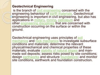
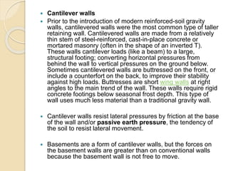
![ Soil properties
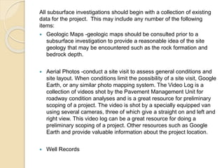
Some of the important properties of soils that are used by
geotechnical engineers to analyze site conditions and
design earthworks, retaining structures, and foundations
are:
Specific weight or Unit Weight
Cumulative weight of the solid particles, water and air of
the unit volume of soil. Note that the air phase is often
assumed to be weightless.
Porosity
Ratio of the volume of voids (containing air, water, or other
fluids) in a soil to the total volume of the soil. Porosity is
mathematically related to void ratio the by[9]
here e is void ratio and n is porosity](https://image.slidesharecdn.com/introductionandgeotechnicalactivities2-221216225834-cdb4c47b/85/INTRODUCTION_AND_geotechnical_activities-2-pptx-9-320.jpg)
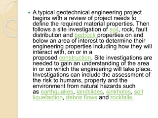
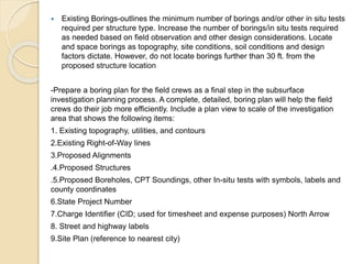
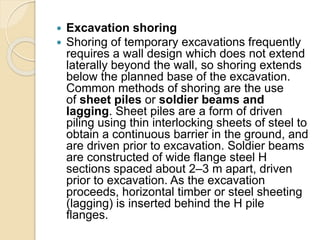
![ Void ratio
The ratio of the volume of voids to the volume of solid particles in a soil mass. Void
ratio is mathematically related to the porosity by[9]
Permeability
A measure of the ability of water to flow through the soil. It is expressed in units of
velocity.[10]
Compressibility
The rate of change of volume with effective stress. If the pores are filled with water,
then the water must be squeezed out of the pores to allow volumetric compression of
the soil; this process is called consolidation.
Shear strength
The maximum shear stress that can be applied in a soil mass without causing shear
failure.[11]
Atterberg Limits
Liquid limit, Plastic limit, and Shrinkage limit. These indices are used for estimation of
other engineering properties and for soil classification](https://image.slidesharecdn.com/introductionandgeotechnicalactivities2-221216225834-cdb4c47b/85/INTRODUCTION_AND_geotechnical_activities-2-pptx-10-320.jpg)
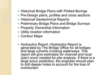
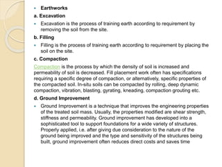
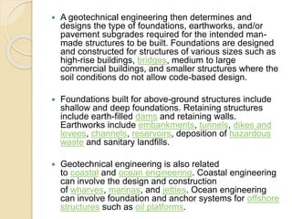
![ Offshore geotechnical engineering
Offshore (or marine) geotechnical engineering is concerned with
foundation design for human-made structures in the sea, away from
thecoastline (in opposition to onshore or nearshore)Oil
platforms, artificial islands and submarine pipelines are examples of
such structures. There are number of significant differences between
onshore and offshore geotechnical engineering.[15][16] Notably,
ground improvement (on the seabed) and site investigation are more
expensive, the offshore structures are exposed to a wider range of
geohazards, and the environmental and financial consequences are
higher in case of failure. Offshore structures are exposed to various
environmental loads, notably wind, waves and currents. These
phenomena may affect the integrity or the serviceability of the
structure and its foundation during its operational lifespan – they
need to be taken into account in offshore design.](https://image.slidesharecdn.com/introductionandgeotechnicalactivities2-221216225834-cdb4c47b/85/INTRODUCTION_AND_geotechnical_activities-2-pptx-30-320.jpg)
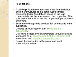
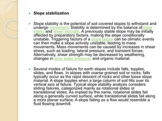
![ In subsea geotechnical engineering, seabed materials are
considered a two-phase material composed of 1) rock
or mineral particles and 2) water] Structures may be fixed in place in
the seabed—as is the case for piers, jettys and fixed-bottom wind
turbines—or may be a floating structure that remain roughly fixed
relative to its geotechnical anchor point. Undersea mooring of
human-engineered floating structures include a large number
of offshore oil and gas platforms and, since 2008, a few floating wind
turbines. Two common types of engineered design for anchoring
floating structures include tension-leg and catenary loose
mooring systems. "Tension leg mooring systems have vertical
tethers under tension providing large restoring moments in pitch and
roll. Catenary mooring systems provide station keeping for an
offshore structure yet provide little stiffness at low tensions.](https://image.slidesharecdn.com/introductionandgeotechnicalactivities2-221216225834-cdb4c47b/85/INTRODUCTION_AND_geotechnical_activities-2-pptx-31-320.jpg)