Downloaded 925 times


![=((radius of main plate-(pin hole/2))*(tm) +(radius cheekplate1-(pin
hole/2))*tce*2+(radius cheekplate2 -(pin hole/2))*tc2e*2)*2
= shear stress / Allowable shear stress
=2*(2* radius of cheekplate(1)* tce)+2*(2* radius of cheek plate(2)*
tc2e)+(radius of main plate*2* (tm))-2* pin hole* (tm)
= Max static sling load *1000/ Area at tension failure
=Tension stress / Allowable tensile stress
=(tce/((tm) +2* tce+2* tc2e))* Max static sling load
= F * 1000 / Aw
= 0.7* (tc)
= shear stress at weld / Allowable shear stress
= ([B]-((tm) +2* 0.75tm+2* tc2e))/2
= 0.1*[B]
= 0.2*[B]](https://image.slidesharecdn.com/padeyedesigncalculation-140110195313-phpapp01/85/Padeye-design-calculation-5-320.jpg)
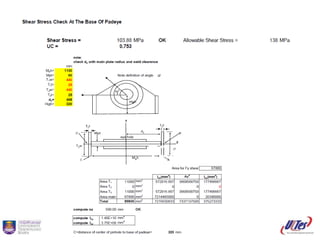
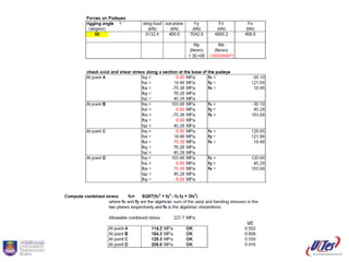
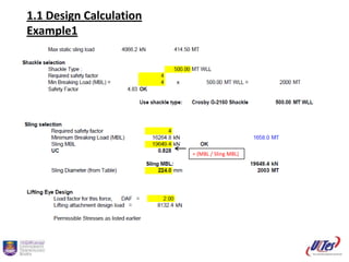
The document provides guidelines for padeye design and calculations for lifting attachments. It states that padeyes shall be designed for at least 5% of the design load applied laterally and that permissible stresses shall follow AISC standards with additional requirements limiting through-thickness stresses to 0.2 times the yield strength if the material does not have through-thickness properties. It then provides examples of calculations for padeye design including shear stress, tension stress, weld shear stress, and dimensional requirements.


