Downloaded 10 times
![• ADD T A B T= A+B
• ADD W C D W= C+D
• LD A, 0(W) A=M[W]
• ST C, 0(B) M[B]=C
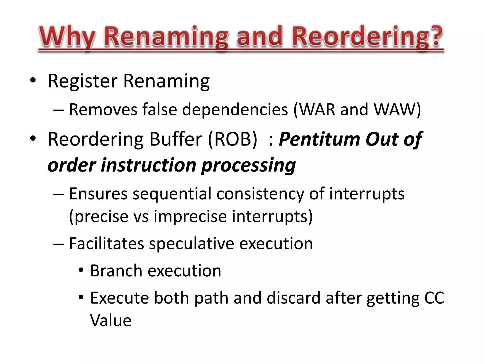
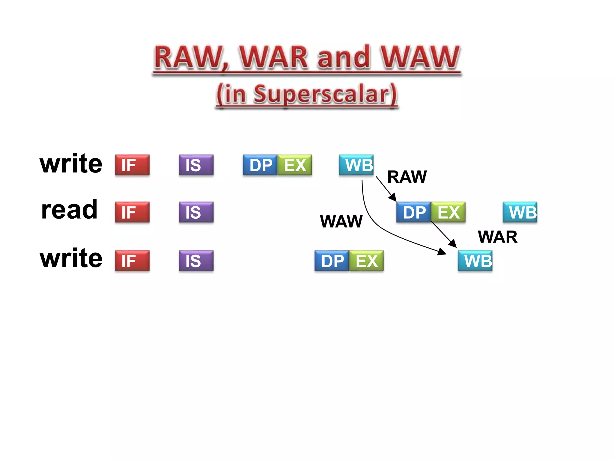
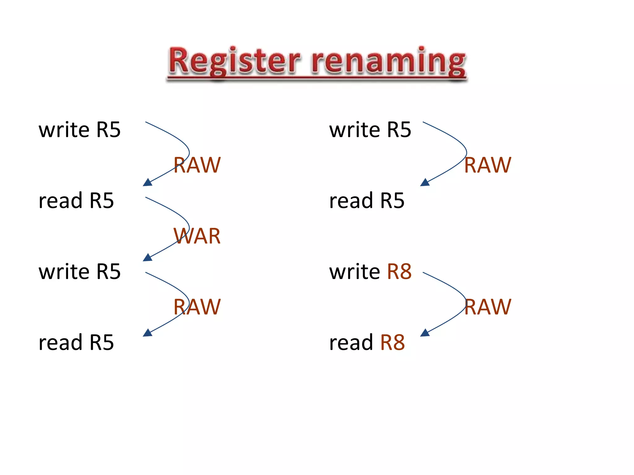
Read After Write (RAW), W after W, W after R
RAW (Ins2-Ins3): True dependency
WAW, WAR (Ins1 ot Ins3) : false dependency](https://image.slidesharecdn.com/lec05-150215030401-conversion-gate02/75/Lec05-16-2048.jpg)
![• ADD T A B T= A+B
• ADD W C D W= C+D
• LD A, 0(W) A=M[W]
• ST C, 0(B) M[B]=C](https://image.slidesharecdn.com/lec05-150215030401-conversion-gate02/75/Lec05-21-2048.jpg)

![• db : define byte dw: def. word (2 bytes)
• dd: def double word (4) dq : def quad word (8)
• equ : equate assign numeric expr to a name
.data
db A 100 dup (?) ; define 100 bytes, with no initial
values for bytes
db “Hello” ; define 5 bytes, ASCII equivalent of “Hello”.
dd PtrArray 4 dup (?) ;array[0..3] of dword
maxint equ 32767 ; define maxint=32767
count equ 10 * 20 ; calculate a value (200)](https://image.slidesharecdn.com/lec05-150215030401-conversion-gate02/75/Lec05-40-2048.jpg)
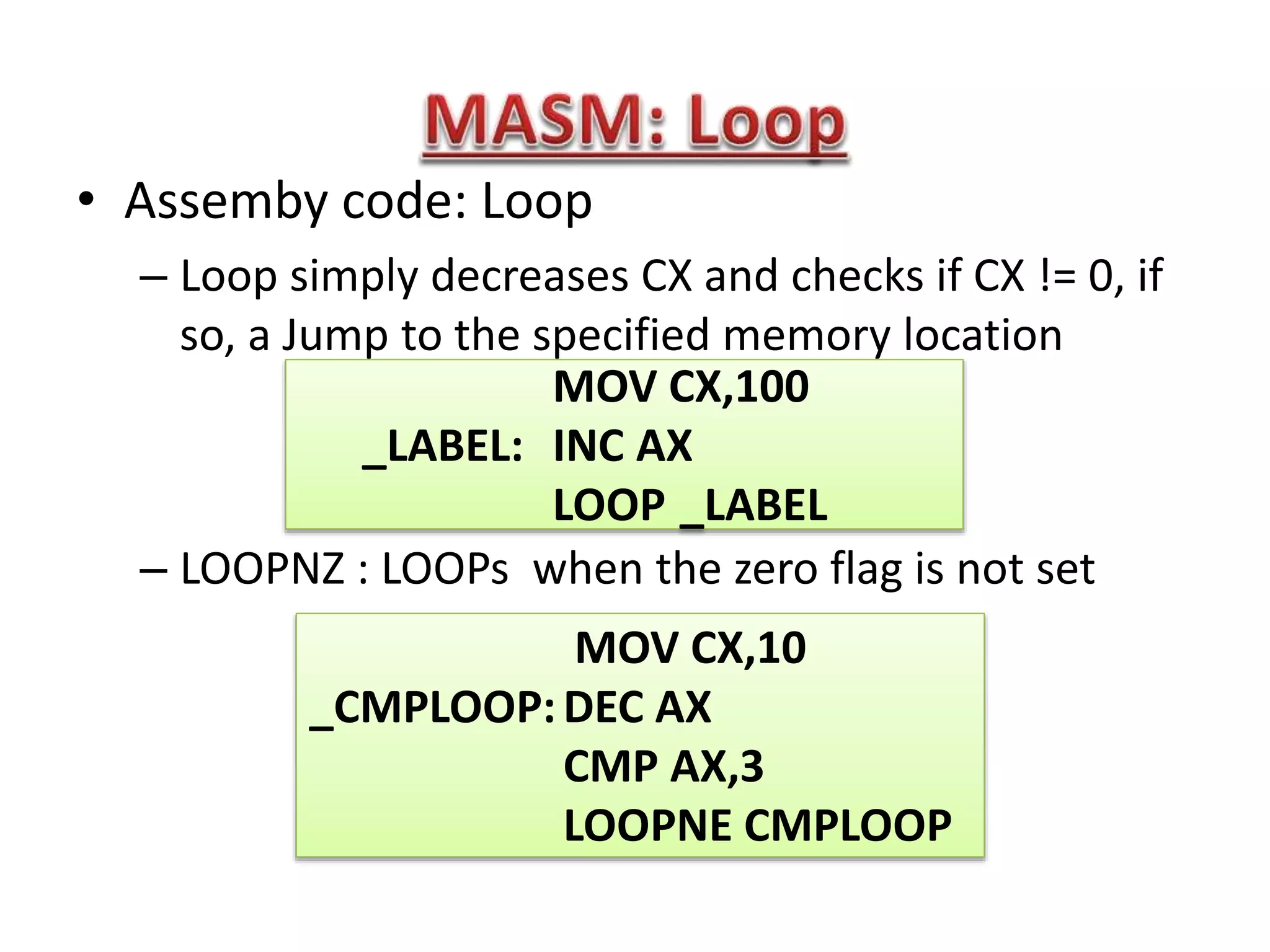
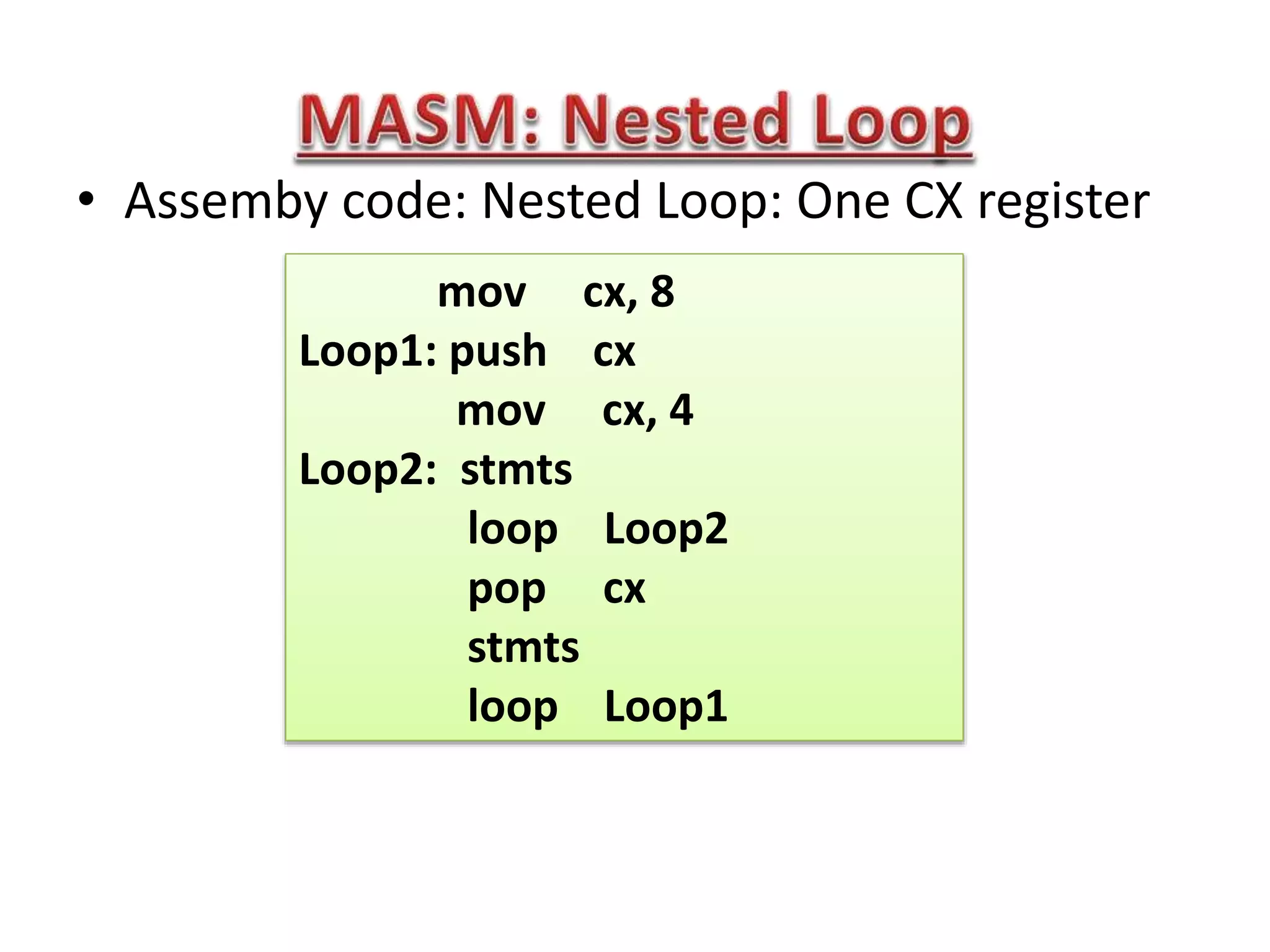
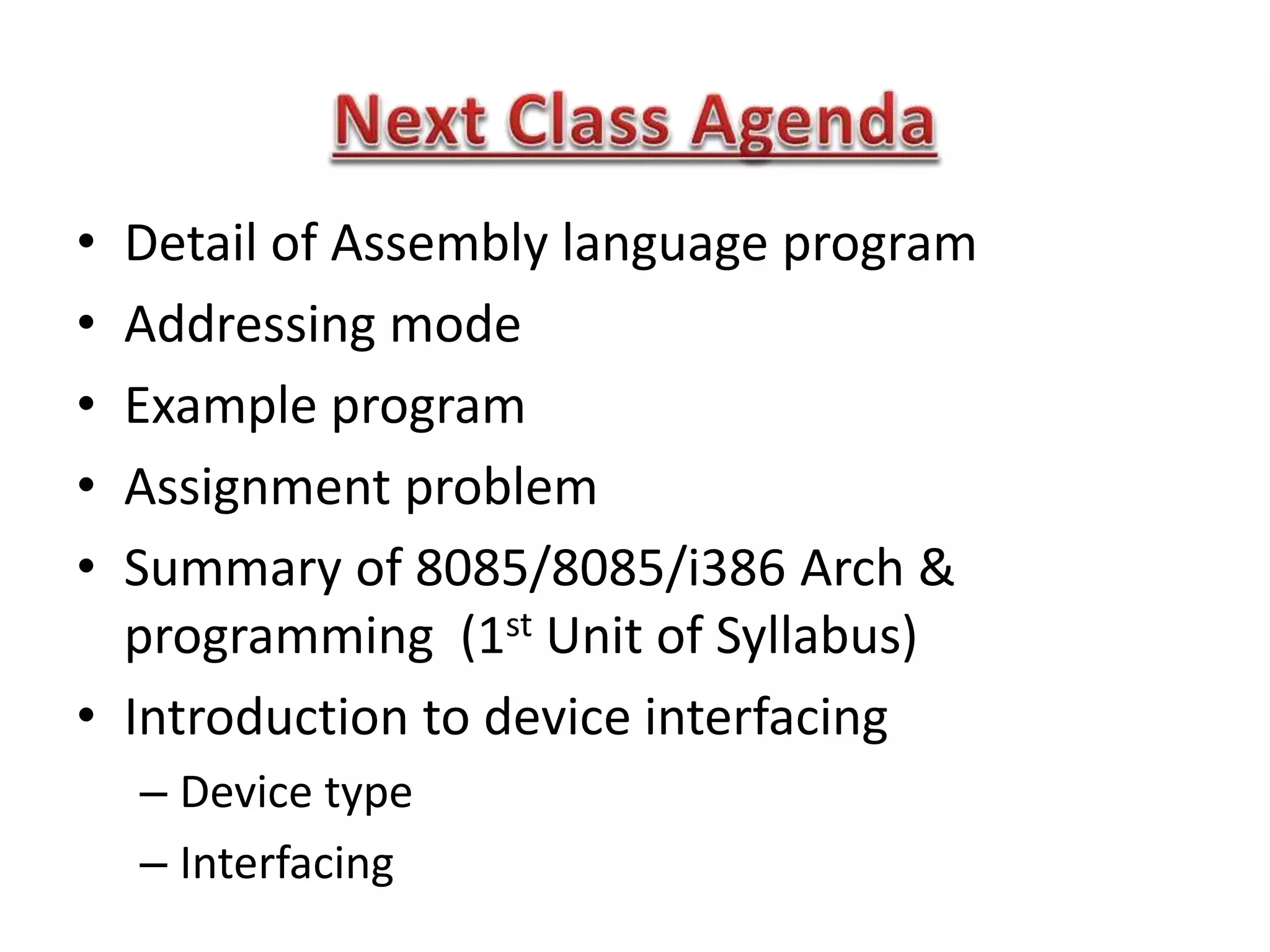


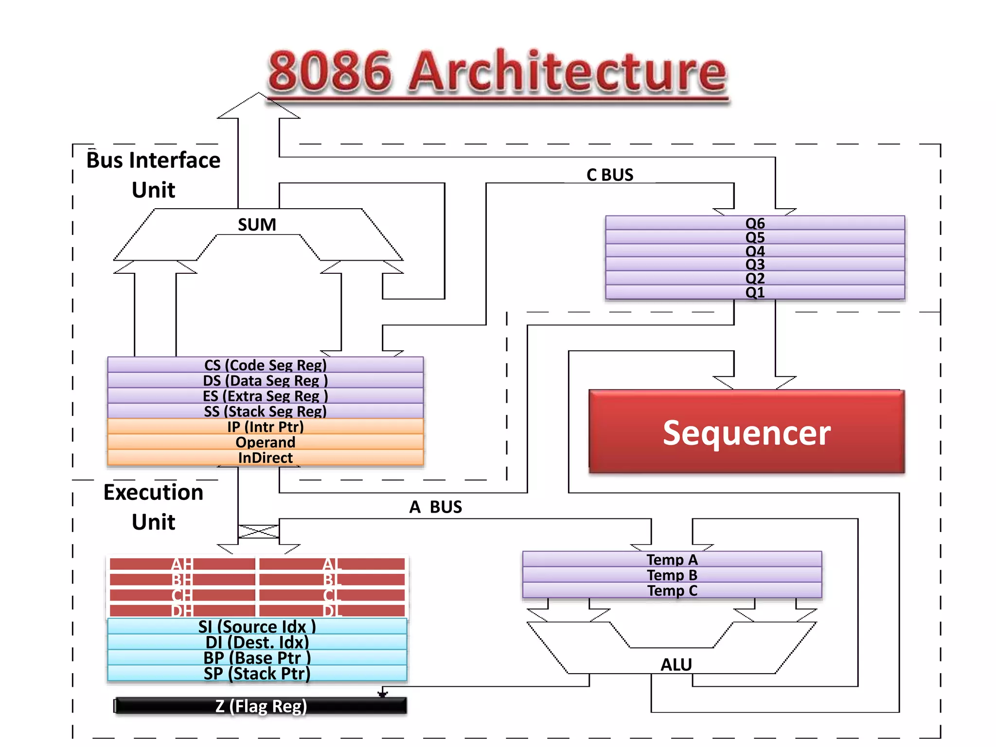
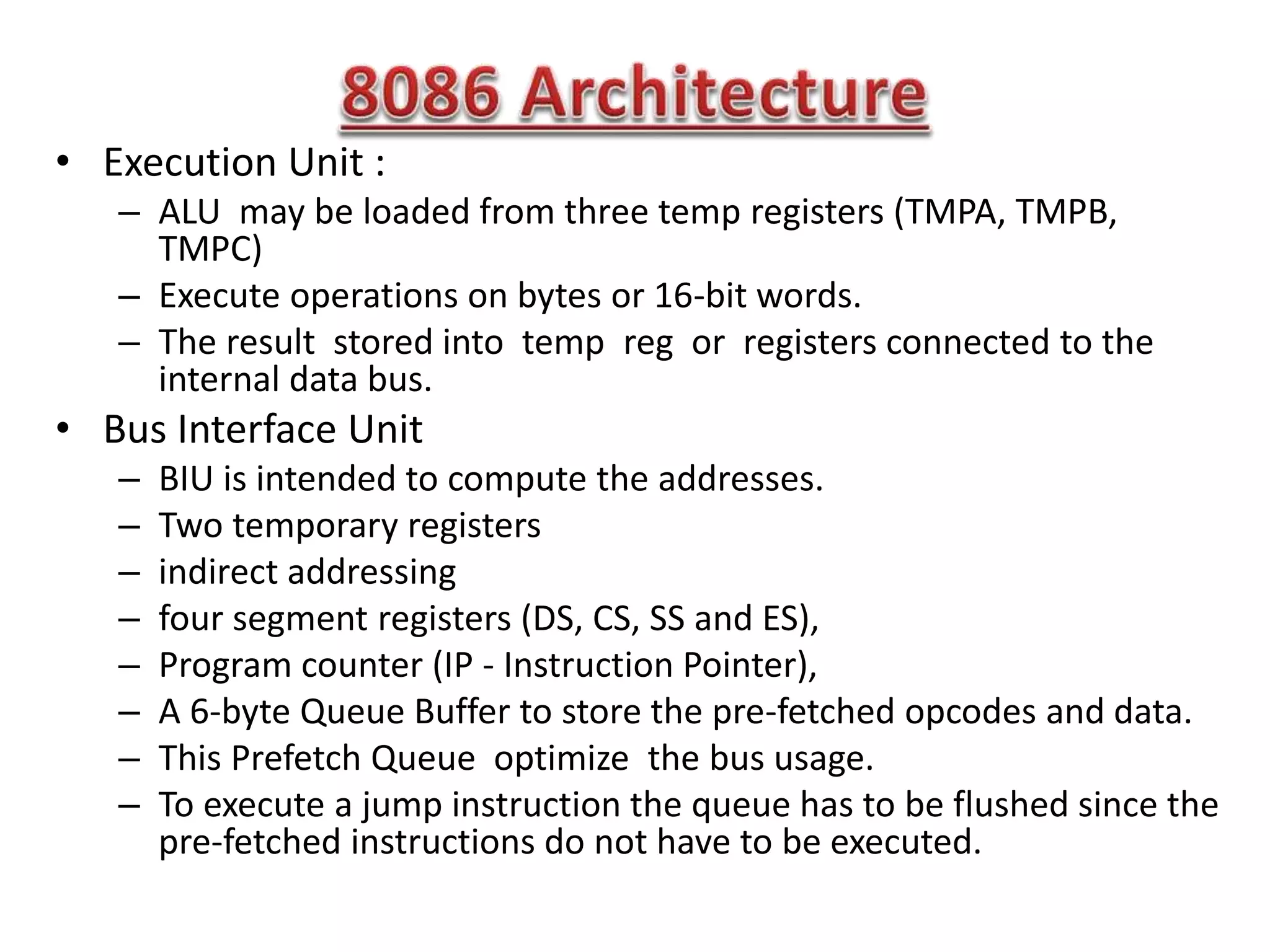
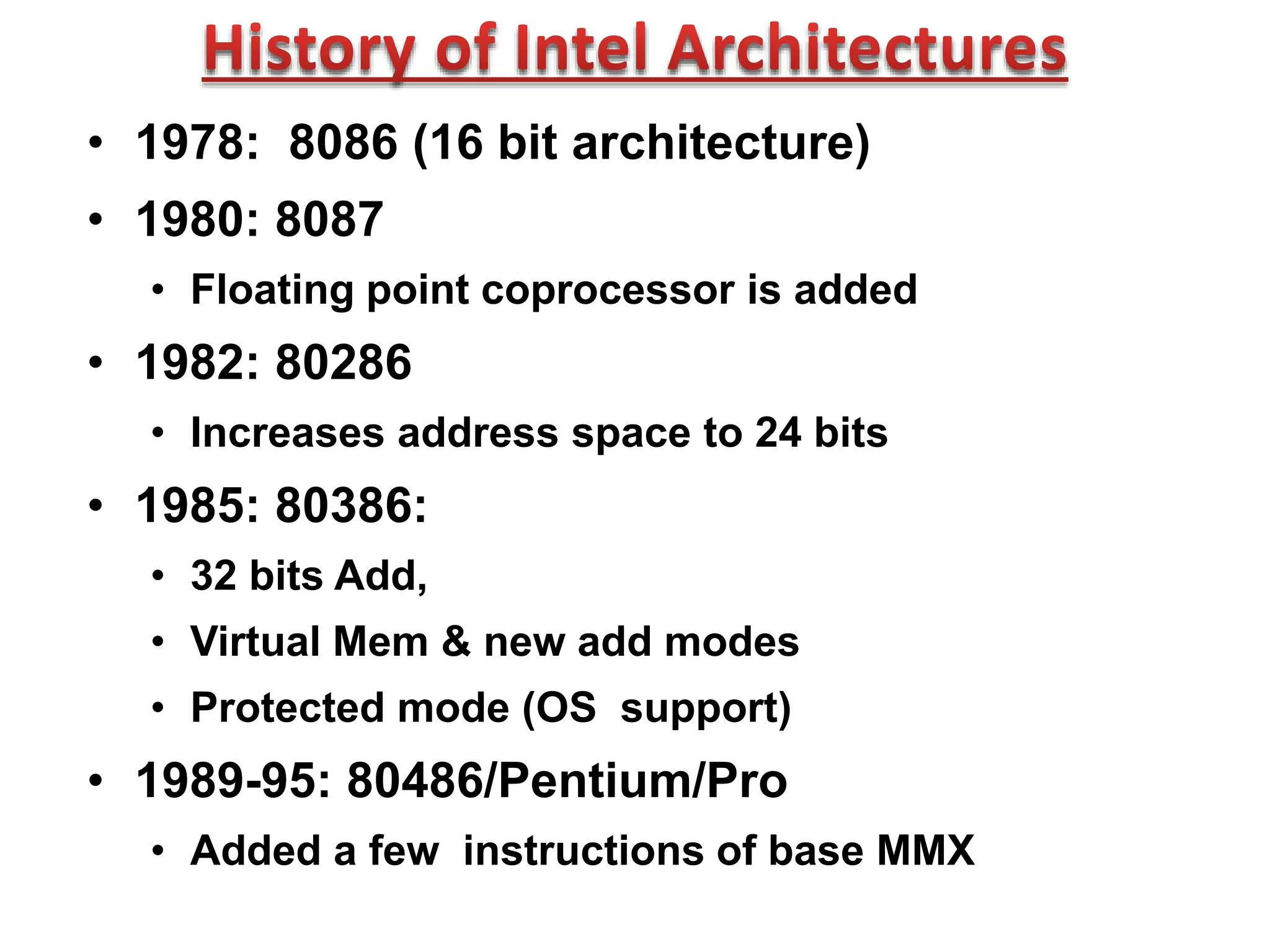
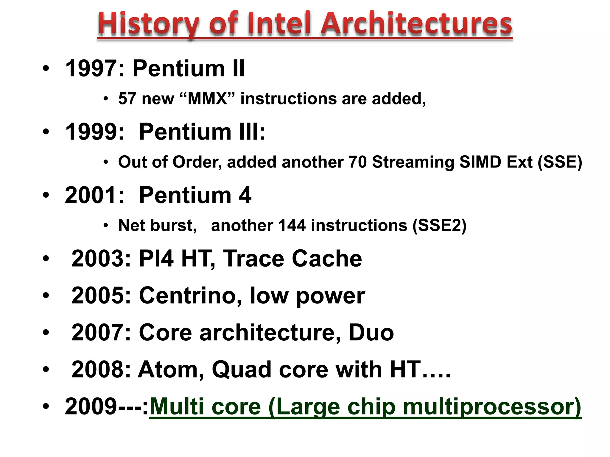
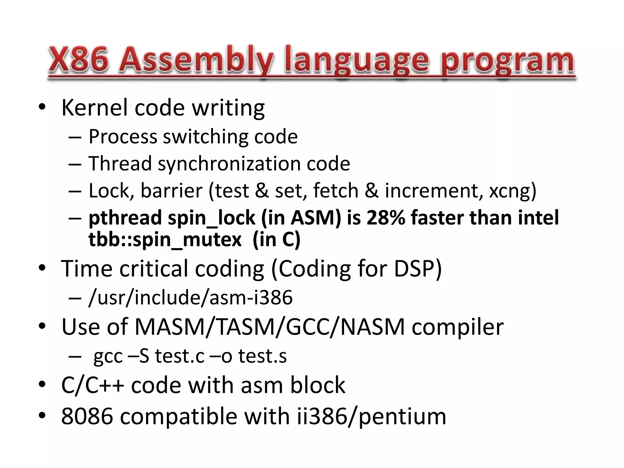
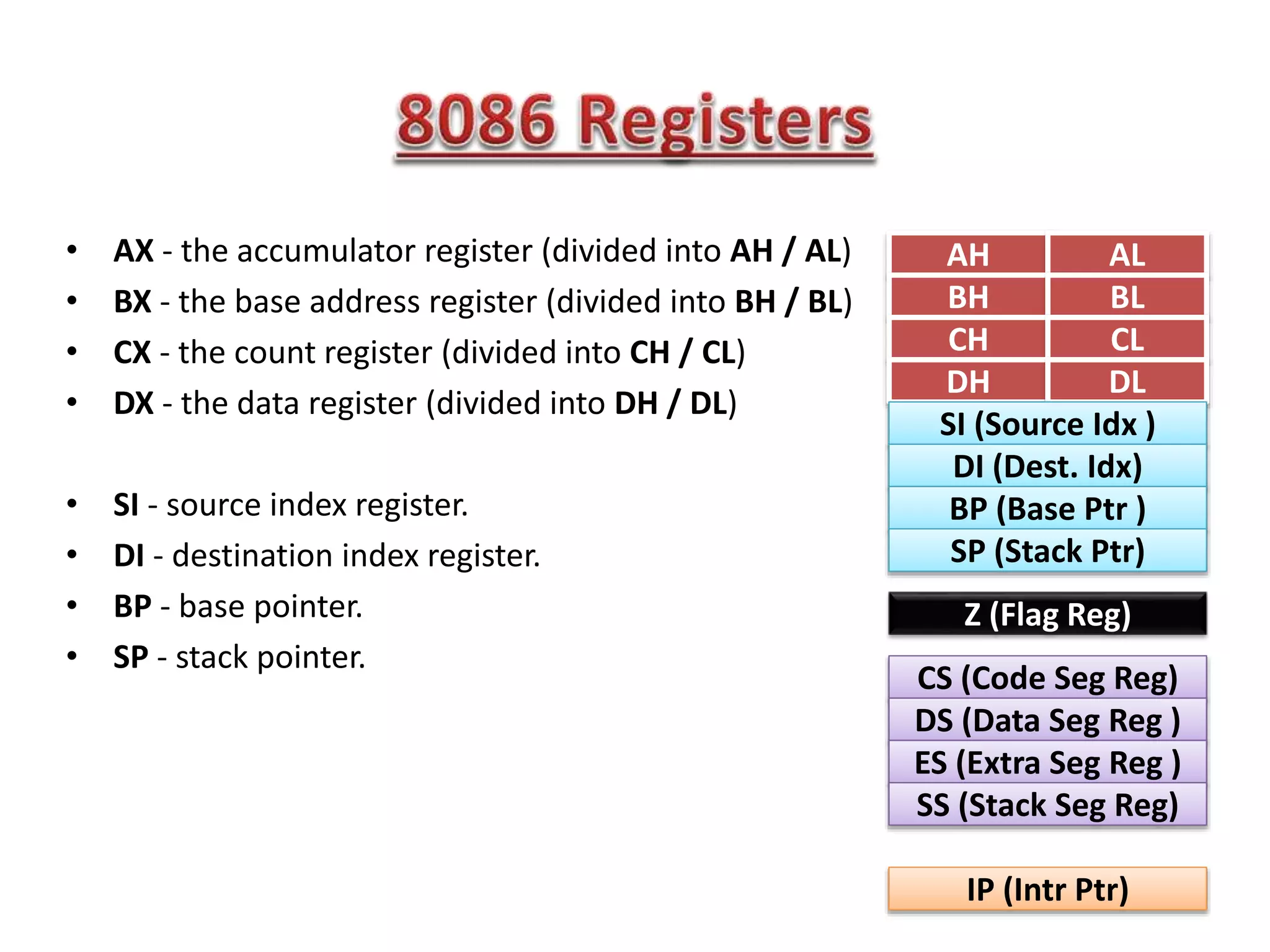
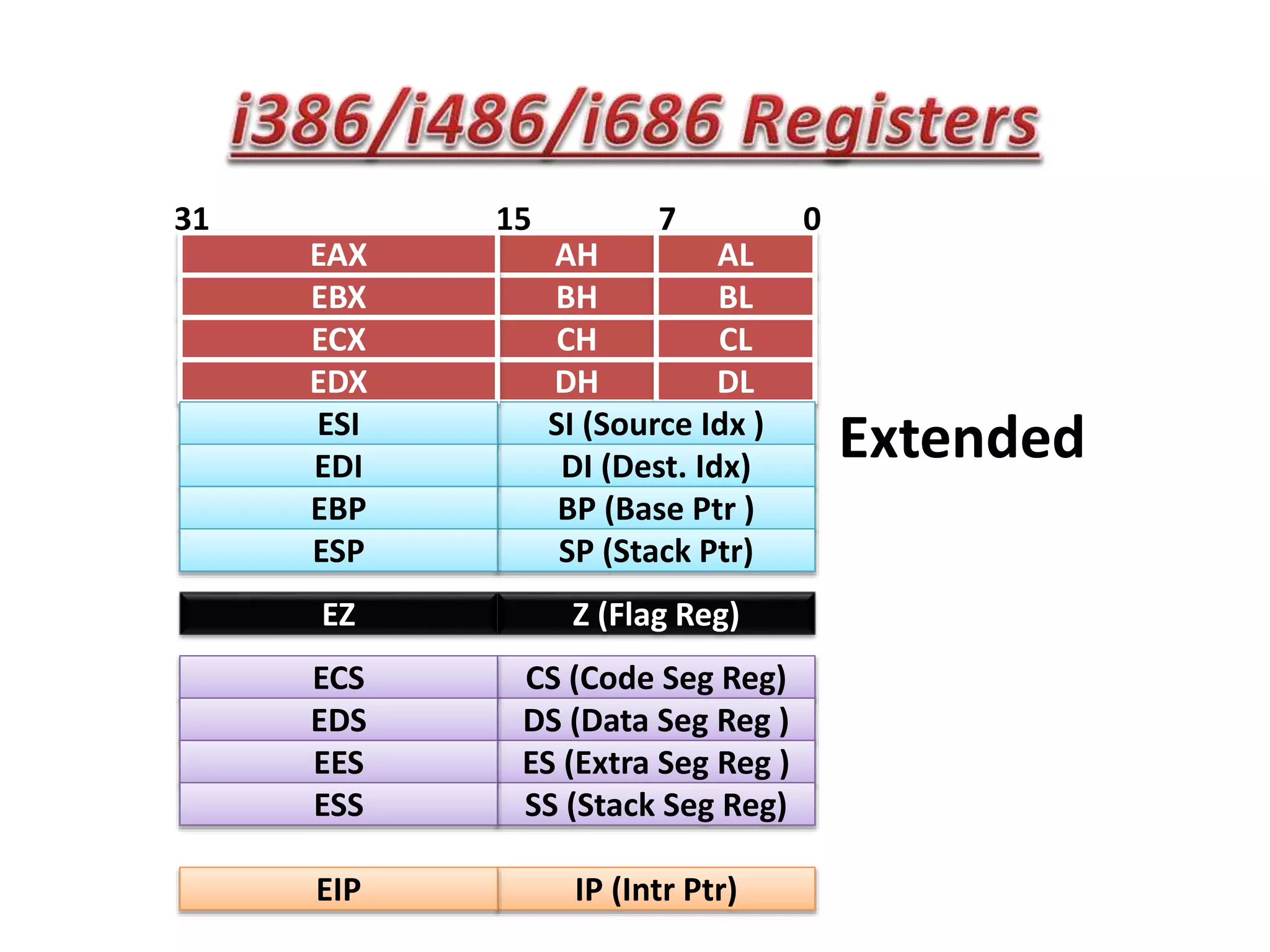
The document summarizes key points about the 8086 microprocessor architecture and assembly language programming. It discusses the 8086 architecture including its registers, data path, and parallel execution units. It also provides examples of assembly language programs using loops and addressing modes. Finally, it outlines the topics to be covered in the next class, including a summary of 8085/8086/i386 architectures and assembly programming basics, as well as an introduction to device interfacing.


![Ilfak Guilfanov - Decompiler internals: Microcode [rooted2018]](https://cdn.slidesharecdn.com/ss_thumbnails/ilfak-keynote-180312223906-thumbnail.jpg?width=640&height=640&fit=bounds)


![Ece iv-fundamentals of hdl [10 ec45]-notes](https://cdn.slidesharecdn.com/ss_thumbnails/ece-iv-fundamentalsofhdl10ec45-notes-150103114952-conversion-gate02-thumbnail.jpg?width=640&height=640&fit=bounds)


