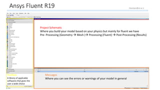
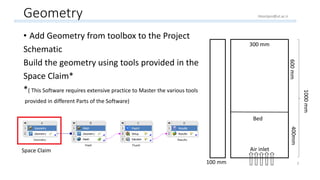
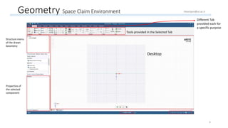
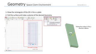
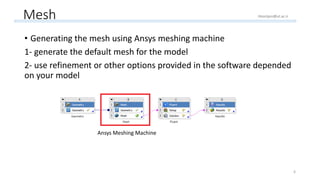
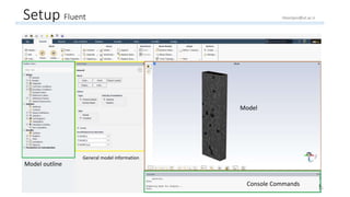
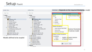
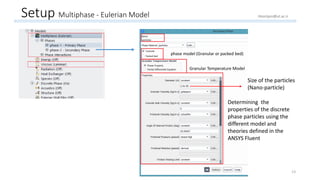
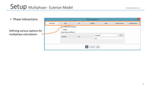
Fluidized Bed modeling using
R19
(Learning ASNYS Fluent 19 Modeling Algorithm)
Hamed Hoorijani
M.Sc. Student at the university of Tehran
Hoorijani@ut.ac.ir
Hoorijani.h@gmail.com
Linked : https://www.linkedin.com/in/hamed-hoorijani/
: Hamed Hoorijani
July 2019
1
Ansys Fluent R19
Project Schematic
Where you build your model based on your physics but mainly for fluent we have
Pre- Processing (Geometry  Mesh ) Processing (Fluent)  Post-Processing (Results)
Toolbox
A library of applicable
softwares that gives the
user a wide choice
Messages
Where you can see the errors or warnings of your model in general
2
Hoorijani@ut.ac.ir
Geometry
• Add Geometry from toolbox to the Project
Schematic
Build the geometry using tools provided in the
Space Claim*
*( This Software requires extensive practice to Master the various tools
provided in different Parts of the Software)
300 mm300 mm
100 mm
1000mm
400mm600mm
Bed
Air inlet
3
Space Claim
Hoorijani@ut.ac.ir
Geometry Space Claim Environment
Desktop
Structure menu
of the drawn
Geometry
Properties of
the selected
component
Tools provided in the Selected Tab
Different Tab
provided each for
a specific purpose
4
Hoorijani@ut.ac.ir
Geometry Space Claim Environment
1- Draw the rectangular of the 2D in the x-z plate
2- Pull the surface and make a volume of the desired Geometry
2D model in xz plate
Pulling the surface in the y-
direction 100mm
5
Hoorijani@ut.ac.ir
Mesh
• Generating the mesh using Ansys meshing machine
1- generate the default mesh for the model
2- use refinement or other options provided in the software depended
on your model
Ansys Meshing Machine
6
Hoorijani@ut.ac.ir
Mesh Ansys Meshing Machine
Displaying defined Mesh
Outline of the project
(Mesh, Named
Selection, Contacts, …)
Details of the
defined Mesh
Details of the
defined Mesh :
Messages of Mesh
Warnings and Alerts of
the errors in the constructed mesh 7
Hoorijani@ut.ac.ir
Mesh Ansys Meshing Machine
Right Click
Sizing a specific part differently from the defined mesh
Meshing properly in the Contact regions (interface of two different bodies)
Refinement of the Mesh
Meshing a Surface in the model (Differently or a surface that
has been missed )
Inflation of the surface mesh
Editing the Nodes
8
Hoorijani@ut.ac.ir
Mesh Refinement
Refinement Ratio
9
Hoorijani@ut.ac.ir
Mesh Selection Name
1 2
10
Hoorijani@ut.ac.ir
Setup Fluent
Console Commands
Model
General model information
Model outline
11
Hoorijani@ut.ac.ir
Setup Fluent
Models defined to be coupled
Depends on the required Multiphase model
Eulerian Parameters
In Eulerian model
Implicit or Explicit Solution
of Volume Fraction
12
Hoorijani@ut.ac.ir
Setup Multiphase - Eulerian Model
Determining the
properties of the discrete
phase particles using the
different model and
theories defined in the
ANSYS Fluent
Granular Temperature Model
phase model (Granular or packed bed)
13
Hoorijani@ut.ac.ir
Size of the particles
(Nano-particle)
Setup Multiphase - Eulerian Model
• Phase Interactions
Defining various options for
multiphase calculations
14
Hoorijani@ut.ac.ir
Setup Boundary Conditions
Inlet condition: velocity 1
15
Hoorijani@ut.ac.ir
Setup Boundary conditions
16
Right Click
Menu  Type
(Defining the type of
boundary condition)
 outflow for outlet
Hoorijani@ut.ac.ir
Setup Methods of Calculation
Approach of calculating the
momentum equations
The mathematical approach to calculate gradient numerically
The mathematical approach to calculate Pressure equation
The mathematical approach to calculate Momentum Scheme
The mathematical approach to calculate Volume Fraction
equation
The unsteady-State scheme of calculation
17
Hoorijani@ut.ac.ir
Setup Calculation Controls
Relaxation Factor in SIMPLE algorithm
for Pressure correction Equation
Relaxation Factor in SIMPLE algorithm
for Momentum Equations
18
Hoorijani@ut.ac.ir
Setup Defining a region (Bed of particles)
Defining the Bed in the Fluidized
Bed Column
1
2 3
19
Hoorijani@ut.ac.ir
Setup Initialization and Patch
Initialization method (Hybrid is default and
standard can be specified by the user)
Compute from: gives each node in the model a first
approximation based on the option you choose
Initial Values of different variables
(the approximation of the first guess)
Initialize and patch options of the initialization
procedure
20
Hoorijani@ut.ac.ir
Setup Initialization of bed (Patch )
Phase
The specific Variable of the bed
that user wants to initialize
Value of the target variable
Determining which Defined region
to be patched
21
Hoorijani@ut.ac.ir
Setup Run (Calculate)
Defining the appropriate residuals for
the model
Convergence criteria for the
model
Time step size for unsteady analysis
Number of time steps for the model Calculate button
22
Hoorijani@ut.ac.ir
Results post- processing
Outline of the model
(Surfaces, Contours,
Volume Rendering)
The properties of
the selected
component in the
above part
23
Hoorijani@ut.ac.ir
• Drawing the plate, line or a point to determine or analysis a variable through that location
Results post- processing
Defining a plane, line or point in the
model using a x,y,z coordinates
Options of the post
processing part in the tab
Specifying the Plane and
the distance in the third
plane and the type of plane
bounds 24
Hoorijani@ut.ac.ir
Results post- processing
• Different visualization techniques for post processing Visualized results
and its legend
The different options
(Contours, Charts,
Volume Rendering)
Determing which
variable and at
what location it
displays
25
Hoorijani@ut.ac.ir
Thanks for your attention ! 
26

Learning ANSYS Fluent R19 using modeling a Fluidized Bed with nano particles

  • 1.
    Fluidized Bed modelingusing R19 (Learning ASNYS Fluent 19 Modeling Algorithm) Hamed Hoorijani M.Sc. Student at the university of Tehran Hoorijani@ut.ac.ir Hoorijani.h@gmail.com Linked : https://www.linkedin.com/in/hamed-hoorijani/ : Hamed Hoorijani July 2019 1
  • 2.
    Ansys Fluent R19 ProjectSchematic Where you build your model based on your physics but mainly for fluent we have Pre- Processing (Geometry  Mesh ) Processing (Fluent)  Post-Processing (Results) Toolbox A library of applicable softwares that gives the user a wide choice Messages Where you can see the errors or warnings of your model in general 2 Hoorijani@ut.ac.ir
  • 3.
    Geometry • Add Geometryfrom toolbox to the Project Schematic Build the geometry using tools provided in the Space Claim* *( This Software requires extensive practice to Master the various tools provided in different Parts of the Software) 300 mm300 mm 100 mm 1000mm 400mm600mm Bed Air inlet 3 Space Claim Hoorijani@ut.ac.ir
  • 4.
    Geometry Space ClaimEnvironment Desktop Structure menu of the drawn Geometry Properties of the selected component Tools provided in the Selected Tab Different Tab provided each for a specific purpose 4 Hoorijani@ut.ac.ir
  • 5.
    Geometry Space ClaimEnvironment 1- Draw the rectangular of the 2D in the x-z plate 2- Pull the surface and make a volume of the desired Geometry 2D model in xz plate Pulling the surface in the y- direction 100mm 5 Hoorijani@ut.ac.ir
  • 6.
    Mesh • Generating themesh using Ansys meshing machine 1- generate the default mesh for the model 2- use refinement or other options provided in the software depended on your model Ansys Meshing Machine 6 Hoorijani@ut.ac.ir
  • 7.
    Mesh Ansys MeshingMachine Displaying defined Mesh Outline of the project (Mesh, Named Selection, Contacts, …) Details of the defined Mesh Details of the defined Mesh : Messages of Mesh Warnings and Alerts of the errors in the constructed mesh 7 Hoorijani@ut.ac.ir
  • 8.
    Mesh Ansys MeshingMachine Right Click Sizing a specific part differently from the defined mesh Meshing properly in the Contact regions (interface of two different bodies) Refinement of the Mesh Meshing a Surface in the model (Differently or a surface that has been missed ) Inflation of the surface mesh Editing the Nodes 8 Hoorijani@ut.ac.ir
  • 9.
  • 10.
    Mesh Selection Name 12 10 Hoorijani@ut.ac.ir
  • 11.
    Setup Fluent Console Commands Model Generalmodel information Model outline 11 Hoorijani@ut.ac.ir
  • 12.
    Setup Fluent Models definedto be coupled Depends on the required Multiphase model Eulerian Parameters In Eulerian model Implicit or Explicit Solution of Volume Fraction 12 Hoorijani@ut.ac.ir
  • 13.
    Setup Multiphase -Eulerian Model Determining the properties of the discrete phase particles using the different model and theories defined in the ANSYS Fluent Granular Temperature Model phase model (Granular or packed bed) 13 Hoorijani@ut.ac.ir Size of the particles (Nano-particle)
  • 14.
    Setup Multiphase -Eulerian Model • Phase Interactions Defining various options for multiphase calculations 14 Hoorijani@ut.ac.ir
  • 15.
    Setup Boundary Conditions Inletcondition: velocity 1 15 Hoorijani@ut.ac.ir
  • 16.
    Setup Boundary conditions 16 RightClick Menu  Type (Defining the type of boundary condition)  outflow for outlet Hoorijani@ut.ac.ir
  • 17.
    Setup Methods ofCalculation Approach of calculating the momentum equations The mathematical approach to calculate gradient numerically The mathematical approach to calculate Pressure equation The mathematical approach to calculate Momentum Scheme The mathematical approach to calculate Volume Fraction equation The unsteady-State scheme of calculation 17 Hoorijani@ut.ac.ir
  • 18.
    Setup Calculation Controls RelaxationFactor in SIMPLE algorithm for Pressure correction Equation Relaxation Factor in SIMPLE algorithm for Momentum Equations 18 Hoorijani@ut.ac.ir
  • 19.
    Setup Defining aregion (Bed of particles) Defining the Bed in the Fluidized Bed Column 1 2 3 19 Hoorijani@ut.ac.ir
  • 20.
    Setup Initialization andPatch Initialization method (Hybrid is default and standard can be specified by the user) Compute from: gives each node in the model a first approximation based on the option you choose Initial Values of different variables (the approximation of the first guess) Initialize and patch options of the initialization procedure 20 Hoorijani@ut.ac.ir
  • 21.
    Setup Initialization ofbed (Patch ) Phase The specific Variable of the bed that user wants to initialize Value of the target variable Determining which Defined region to be patched 21 Hoorijani@ut.ac.ir
  • 22.
    Setup Run (Calculate) Definingthe appropriate residuals for the model Convergence criteria for the model Time step size for unsteady analysis Number of time steps for the model Calculate button 22 Hoorijani@ut.ac.ir
  • 23.
    Results post- processing Outlineof the model (Surfaces, Contours, Volume Rendering) The properties of the selected component in the above part 23 Hoorijani@ut.ac.ir
  • 24.
    • Drawing theplate, line or a point to determine or analysis a variable through that location Results post- processing Defining a plane, line or point in the model using a x,y,z coordinates Options of the post processing part in the tab Specifying the Plane and the distance in the third plane and the type of plane bounds 24 Hoorijani@ut.ac.ir
  • 25.
    Results post- processing •Different visualization techniques for post processing Visualized results and its legend The different options (Contours, Charts, Volume Rendering) Determing which variable and at what location it displays 25 Hoorijani@ut.ac.ir
  • 26.
    Thanks for yourattention !  26