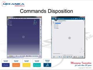
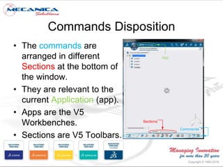
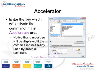
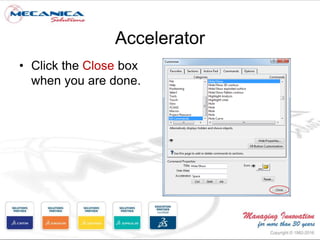
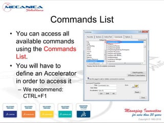
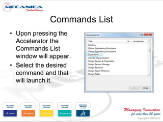
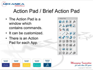
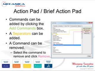
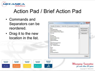
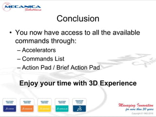
Working with CATIA V5 in 3DEXPERIENCE 2017x updated platform. Learn how to access commands and functions.
Get more free 3DEXPERIENCE apps demo here:
http://www.mecanicasolutions.com/3dexperience-webinar-ondemand/
Commonly referred to as a 3D Product Lifecycle Management software suite, CATIA supports multiple stages of product development (CAx), including conceptualization, design (CAD), engineering (CAE) and manufacturing (CAM). CATIA facilitates collaborative engineering across disciplines around its 3D EXPERIENCE platform, including surfacing & shape design, electrical, fluid and electronic systems design, mechanical engineering and systems engineering.
When it comes to learning the art and science of Catia Drafting, it is not that difficult provided you are well acquainted with the way it is really done. When it to drafting in Catia, then you can rest assured that it is not particularly difficult as such is provided that you know how to go about doing it, that is.
This document provides an overview of CATIA V5 software for industrial training purposes. It covers the following key points in 3 sentences:
CATIA V5 is a 3D modeling software used for mechanical design that incorporates CAD, CAM, and CAE applications. The document outlines the CATIA user interface and common commands, and provides examples of how to use the sketching, part design, and assembly modeling modules to create 3D models from 2D profiles and assemble multiple parts. It summarizes the capabilities of these modules and how they can be used to efficiently create and modify complex 3D models.
CATIA is an integrated computer aided engineering software that incorporates CAD, CAM, CAE, and other applications. It has a user friendly graphical interface and uses parametric and variational modeling techniques. Some of the main applications include part design, assembly design, sketching, drafting, surfacing, finite element analysis, and manufacturing. The sketcher is used to create 2D sketches that can be extruded or revolved into 3D parts. Parts are constructed from features and stored in the specification tree for easy modification. CATIA supports the entire product development process from design to manufacturing and analysis.
CATIA is a 3D CAD software created by Dassault Systèmes. It is used in industries like aerospace, automotive, and shipbuilding. CATIA allows users to create 3D models of parts and assemblies. It provides tools for sketching, part design, sheet metal design, and more. Key features include the specification tree to view a part's design history, assembly design tools to combine parts while defining relationships and constraints, and surface modeling tools for complex shapes.
Differences in macros between catia v5 and catia v6 or 3dexperienceFernando Petre
- Macros created for CATIA V5 may not work in CATIA V6 or 3DEXPERIENCE without modifications due to differences in the automation objects, methods, and properties between the versions.
- The path and filenames for macro documentation (CHM files) differ between CATIA V5, V6, and 3DEXPERIENCE installations.
- Comparing macro code samples between versions shows changes needed in 3DEXPERIENCE code, even for macros provided in its installation folder. Users must check and modify macros to accommodate differences in the newer versions.
- While some macros may port over between V6 and 3DEXPERIENCE with minor changes, macros will generally need to be significantly modified
CATIA DMU Kinematic Simulation - TecnisiaCAD RAVI RAI
CATIA V5 DMU ENABLES DIGITAL PRODUCT SIMULATION, ANALYSIS AND VALIDATION, IMPROVING PRODUCT QUALITY AND ACCELERATING DECISION MAKING BY PROVIDING REAL-TIME INSIGHT INTO REAL-WORLD PRODUCT PERFORMANCE.
http://tecnisiacadtraining.business.site https://www.sulekha.com/tecnisiacad-janakpuri-delhi-contact-address
CATIA started as an in-house CAD software developed by Dassault Aviation in 1977. It supports multiple stages of product development including conceptualization, design, engineering, and manufacturing. CATIA facilitates collaborative engineering across disciplines through its 3DEXPERIENCE platform. Key applications within CATIA include part design, assembly design, sketching, drafting, surfacing, finite element analysis, and manufacturing.
if you want to be a pro designer then this catia v5 which is advance and powerful for 2-D and 3-D designing software help you definitely .
credit:-Mr.vijay singh ( trendy updates guest blogger )
This document contains 31 questions and answers related to CATIA V5. Some of the key topics covered include:
- The file extension for CATIA sketcher files is .catpart
- Construction elements assist in sketching profiles in the sketcher workbench
- Three dimensions (major axis, minor axis, distance from origin) are required to constrain an ellipse
- The color codes for ISO-constrained, under-constrained, and over-constrained elements are green, white, and magenta respectively
This document provides an overview of AutoCAD software and its applications. It discusses that AutoCAD has over 6 million users and is the 5th largest software company. It is used widely for 2D drafting and 3D modeling across many industries like engineering, architecture, and construction. The document outlines the tools used for 2D drafting like lines, rectangles, and modifying tools. It also summarizes 3D modeling tools like box, extrude, and presspull. It highlights the demand for AutoCAD skills in the job market and lists some partner companies that hire graduates with AutoCAD knowledge.
AutoCAD is CAD software developed by Autodesk to allow for 2D and 3D modeling and drafting. It has been in use since 1982 and has evolved through numerous versions. The latest versions have new features like apps integration and support for Windows 8. AutoCAD is widely used in industries for drafting and design work as it enhances productivity. Career options using AutoCAD skills include drafting professional, CAD engineer, and architecture design.
This document introduces AutoCAD software. It defines AutoCAD as a software program used to design 2D and 3D images that provides tools for detailed product design and layout. AutoCAD can be used by designers to visualize imaginary product views and make changes before finalizing a design. It offers flexibility for implementing ideas and presenting designs to clients. AutoCAD is popular among architects, engineers, and builders for developing project layouts. It replaces traditional drafting methods and offers benefits like time savings, increased productivity, and quick 3D prototyping.
The document provides an overview of the 3DEXPERIENCE Platform user experience. It describes the main interface elements including the top bar with options like the compass app name, search bar, user profile, and help. The compass allows instant access to all apps. The search bar allows searching across all content, while the 6W tags provide filtering. Users can also create customized dashboards and access video tutorials.
This document provides an introduction to CATIA V5's Assembly Design workbench. It allows users to assemble parts (CATParts) into larger assemblies (CATProducts). CATProducts contain a specification tree that defines the product structure and maintains part positions using assembly constraints. The workbench provides toolbars for tasks like adding components, applying constraints, and creating symmetrical assemblies. It also enables assembly operations and contextual links between parts.
A press tool assembly ppt.
CATIA (an acronym of computer aided three-dimensional interactive application, pronounced /kəˈtiə/) is a multi-platform software suite for computer-aided design (CAD), computer-aided manufacturing (CAM), computer-aided engineering (CAE), PLM and 3D, developed by the French company Dassault Systèmes.
This document provides an overview of the CATIA V5 software, including:
- A course schedule covering part design, assembly modeling, wireframes, drafting and finite element analysis.
- Descriptions of the CATIA applications for product structure, part design, assembly design, and other tools.
- Information on how to interact with and get help within the CATIA interface.
NX is an advanced CAD/CAM/CAE software originally developed by Unigraphics and now owned by Siemens. It is used for design, engineering analysis, and manufacturing of finished designs. NX provides capabilities for CAD, parametric modeling, simulation, sheet metal design, assembly modeling, and CAM. It is a competitor to software packages like CATIA, Creo, Autodesk Inventor, and SolidWorks.
This document provides tips and tricks for using Creo Parametric 3.0. It discusses options for customizing the user interface and environment, creating mapkeys for commands, leveraging advanced part and assembly modeling techniques, managing large assemblies, using the mechanism application, and working efficiently in drawings. Specific tips covered include customizing system colors, using intent references to make features more robust, controlling assembly constraint behavior, displaying set datums, and sorting BOM tables by assembly sequence.
This document presents an outline for a presentation on AutoCAD 2013. It will cover the introduction to AutoCAD including its history and latest version. It will demonstrate the AutoCAD screen and interface. It will explain the coordinate system and demonstrate various 2D and 3D commands. Examples of 2D and 3D modeling projects will be shown. The presentation will conclude by discussing the benefits of using AutoCAD software.
SOLIDWORKS 3D CAD 2022 introduces improvements to assembly performance and workflows, expanded use of detailing mode, more efficient geometric dimensioning and tolerancing, hybrid modeling capabilities, enhanced part modeling tools, cut list support in bills of materials, configuration tables, structure system and weldment tools, improved import and display performance, and better collaboration through integration with the 3DEXPERIENCE platform. These updates aim to help users speed up their design process.
The document provides an overview of AutoCAD and computer-aided design (CAD) drafting capabilities. It discusses key features of AutoCAD including 2D and 3D modeling, file formats, workspace areas, and common drafting tools. Drafting in AutoCAD involves using lines, circles, arcs, and other basic shapes to accurately depict designs that can be used for manufacturing or construction plans. Parameters can also be set in AutoCAD to make drawings dynamically adjustable.
Every engineer communicates with a common language called "Engineering Drawings". The technique of producing engineering drawings is DRAFTING. AutoCAD is used as a defacto standard for Drafting worldwide.
The course explores the latest tools and techniques of the software package covering all draw commands and options, editing, dimensioning, hatching, and plotting techniques available with AutoCAD Training. The textbook, helps in advancing the frontiers of the software, takes the user across a wide spectrum of engineering solutions through progressive examples, comprehensive illustrations, and detailed exercises, thereby making it an ideal solution for both the novice and the advanced user.
This document provides an overview of AutoCAD and introduces its main features and tools. It discusses how to install and open AutoCAD, describes the basic user interface including menus, toolbars and command line. It also explains how to construct and modify drawings using tools like lines, circles, text, hatches, and modify tools like move, copy, erase. Layers and common mistakes are also covered. Support resources are listed such as lecture notes, exercises and afternoon classes to help students learn AutoCAD.
This document provides shortcuts for searching for different object types and commands in the 3DEXPERIENCE platform. It lists shortcuts for finding physical products, 3D parts, drawings, materials, and other items. Common search shortcuts include prd:, 3dpart:, drw:, mat:, and doc:. It also outlines shortcuts for top bar commands like Ctrl+C for copy and Ctrl+V for paste. Scene layout shortcuts are provided to zoom and navigate the tree view.
This document provides instructions and download links for Dassault Systemes CATIA V6 R2012x software with a crack by SSQ to remove licensing restrictions. It notes the system requirements including a 64-bit CPU, 8GB RAM, and Windows 64-bit to run the Enovia server software. Instructions are given to install the Enovia server, replace the license server with SSQ's cracked version, and then install the 32-bit or 64-bit CATIA client software depending on the computer system. Registration on the forum is required to access the direct download links.
CATIA is a 3D CAD software developed by Dassault Systemes and IBM using C++. It has various workbenches for part design, assembly design, drafting, sheet metal design, and DMU kinematics. The part design workbench allows users to create features like pads, shafts, planes, holes, fillets, drafts, shells, and more. The assembly design workbench enables inserting, moving, rotating, and constraining components. Additional workbenches provide functions for wireframe and surface modeling, drafting views and dimensions, and sheet metal design tools.
The document summarizes the CATIA modeling and kinematics project of a nitro RC car completed by a group of students. It describes the components modeled by each group member, including the engine, frame, suspension, transmission, and other parts. The group encountered many challenges with CATIA crashes and file corruption during the over 60 hours spent on the complex kinematics and assembly modeling of the over 200 components car.
The document provides an overview of CATIA V5 software and its various modeling tools. It discusses the software scenario, sketcher workbench, part design workbench, surface-based features, generative shape design, assembly, and drafting. The sketcher section describes how to create sketches using lines, arcs, circles, splines, and add constraints. The part mode section explains how to use pads, multi-pads, and drafted filleted pads to extrude profiles.
The document appears to be notes from a presentation on the 3DEXPERIENCE platform modules. It discusses several modules including 3DSwym for social collaboration, 3DSearch for searching content, 6WTags for tagging and filtering searches, 3DCompass as a dashboard for accessing apps, and 3DDashboard for creating business dashboards. It also covers the 3DPassport single sign-on system and Platform Management for administering users and roles.
The document discusses the potential of virtual reality (VR) and immersive virtuality (iV) technologies for commerce applications. It summarizes Dassault Systemes' involvement in VR through its iV Lab. The document then outlines several use cases for VR across the product lifecycle from design to sales and training. It acknowledges challenges of VR technologies like head-mounted displays but argues these can be addressed. The document promotes VR as enabling more intuitive product experiences for customers and more efficient processes for companies.
This is a proposal to support unification of skeleton streaming formats and enable a braoder compatibility between mocap systems and realtime 3D softwares
This has been shared alsready with major harware vendors and implemented in some Dassault Systèmes solutions
It is here proposed as a reference to support a potential integration directly within VRPN
This document provides tips and best practices for using photos and formatting text in PowerPoint presentations. It discusses how to use photos effectively without making the presentation heavy or destroying the style. Good samples are provided of using simple photos that are on theme and clean. The document also covers font selection and formatting text for clarity, recommending using the same font without too many colors or styles. Overall it emphasizes keeping the presentation simple, clean and easy to read.
This application will save your time doing boring operations. Functionalities included:
- hide, show, select different elements in CATProduct or CATPart
- macros for Assembly workbench (move selected elements, export points to Excel, search and select same parts in specification tree).
- macros for Part Design workbench (create unfolded body, create center and axis for holes, create coordinate points).
- macros for Drafting workbench (hide/show frames, lock/unlock views, open drawing source) .
- tools for CATIA (capture screenshots, CATIA screenshot to PowerPoint, delete, back-up and restore CATSettings, copy names to clipboard).
Download link : http://www.adinnovation.ro/V5TimeSavingToolbar.zip
Download short pdf presentation : http://www.adinnovation.ro/V5TimeSavingToolbar.pdf
[Seminar]Catia 3D Master with 3dexperience Jimmy Chang
The document discusses the transition from 2D design to 3D design using 3D Master. It describes the current 2D design process and the business challenges it poses, such as delays, cost overruns, and quality issues. The document then introduces the 3D Master concept which uses a single 3D model as the authoritative source of product information. Case studies are presented of companies that implemented 3D Master and achieved benefits like 50% reduction in development costs and change process time. The 3D Master approach is described across the entire product development process from concept to production.
The document provides information on Visual Basic .NET (VB.NET) programming, including an introduction to VB.NET, the integrated development environment (IDE), common controls used in VB.NET, and an example "Hello World" program. It describes the VB.NET IDE layout including the toolbox, solution explorer, properties window, and code editor. It also discusses naming conventions, common controls like buttons and textboxes, and the layout toolbar for arranging controls.
The document provides an overview of programming in Alice. It defines a computer program as a set of instructions that tell a device what to do. The basic elements of a program are described as sequential processing, conditional execution, looping/iteration, and functions. An Alice program can create animated stories, interactive worlds, and games. The Alice code editor is explained, including the camera view, methods panel, code editor, and control panel. Methods in Alice are described as procedural or functional sets of code. Key elements of writing code in Alice like parameters, required parameters, optional parameters, selecting objects, running programs, and using control structures are summarized. The document also reviews editing code through undo/redo, modifying statements, reordering statements,
This tutorial provides instructions for a very basic irrigation design in IRRICAD including:
- Entering zone and mainline items and drawing a simple system
- Turning valves on to indicate which zones will operate simultaneously
- Sizing pipes based on required pressures
- Reading reports to review the design
The goal is to illustrate fundamental concepts that can be applied to more complex designs, such as distinguishing between zone and mainline items and setting the operating scheme before pipe sizing.
The document provides instructions for using various drawing commands in AutoCAD 2013, including:
1. The LINE command is introduced for creating single straight line segments by specifying start and end points. Tips are provided for continuing lines or undoing the last segment.
2. The Cartesian coordinate system used in AutoCAD is described, including absolute coordinates using x,y values, relative coordinates using delta x,y values, and polar coordinates using distance and angle.
3. The ORTHO command is referenced for drawing lines at angles that are multiples of 90 degrees, which constrains drawings to horizontal and vertical orientations.
Gemini Architectural is Professional Cad and Cam Training Institute. We Provide Autocad Training at a professional Level. Autocad architectural Designing Software used by cad and cam engineers. Is basically Cover 2 version 2D and 3D.
This chapter discusses account administration and the administration panel. The administration panel allows administrators to manage all aspects of the website such as settings, design, tools, security, and more. It is divided into several sections - the adminbar menu at the top provides access to all features, the left column lists modules, and the main panel displays settings for the selected feature. The administration panel gives administrators full control over the website and should be kept secure since it allows removing the site entirely. Proper administration settings are also important as they determine aspects like the site name, language, and features.
This chapter discusses account administration on a website built using uCoz. It covers the administration panel interface and various settings that can be configured through it, including common site settings, design management, tools, security, and paid services. The administration panel contains modules for different site functions that are accessible through the main menu. Key account settings that can be configured on the general settings tab include the site name, address, language, and more.
The document provides an overview of the Adobe Premiere Pro editing interface and its key components. It describes the various panels such as the Project, Timeline, Source Monitor, Program Monitor, Effects, and Audio Mixer panels. It explains how workspaces can be customized by rearranging panels, docking them together in frames, or using them as floating panels. The document also provides steps for creating a customized workspace layout.
This document provides an overview of the AutoCAD software interface and its main components. It describes the workspace area where drawings are created, as well as menus, toolbars, palettes and command line that are used to launch commands. It also explains other interface elements like status bar, snap and grid settings, object snaps, and options to customize the software. Context sensitive help features are also summarized.
This document provides an overview of various AutoCAD commands. It begins by explaining that nearly every action in AutoCAD is based on a command, and that commands are used to tell AutoCAD what actions to perform. It then lists some common ways to start commands, such as through menus, toolbars, or the command line. The document proceeds to explain important keyboard shortcuts and details of the command prompt. It concludes by listing and briefly explaining key drawing, editing, and text commands in AutoCAD.
The document provides instructions for installing and customizing features in Microsoft Office 2007. It discusses how to open the Control Panel, click on Installed Programs, select the Office program to change, and click Change. It describes the Settings dialog box where you can add or remove features by expanding folders and selecting installation options. It also covers updating or installing features and describes keyboard shortcuts for navigating features and changing installation options.
Introducing STATA is a document that summarizes the key features and capabilities of the statistical software package STATA. It describes STATA as a powerful and flexible package for statistical analysis, data management, and publication-quality graphing. The document outlines STATA's main interface elements including its command window, results window, variable window, and other windows. It also explains how to import and export data, use do-files to record analyses, and manage variables through labeling, generating new variables, and replacing values.
Some tips on how to get started with MapBasic, the scripting language for MapInfo Pro.
What is MapBasic? Where do I find support and what tools should I use? How do I work with the interface?
This document provides an overview of creating an interactive prototype in Adobe Flash (now called Animate). It discusses setting up a Flash file and introducing basic concepts like drawing shapes, converting objects to symbols, adding frames and keyframes, using layers, and introducing basic ActionScript. It then covers adding animations using tweens, filters and color effects, and creating looping movie clips. The goal is to learn the fundamentals of Flash to quickly prototype applications without extensive programming knowledge.
Start developing projects with Scratch ProgrammingPrakritiDhang
Scratch is visual programming language, where you can develop interactive projects. This targets to children in primary and middle schools, where they can start learning new way of developing projects. This starts with the basics of start learning scratch. This tool is open to all age group.
The document provides 20 tips for improving Solidworks skills organized into sections on sketches, part modeling, assemblies, and drawings. It summarizes each tip in 1-2 sentences with images and links to video examples. The tips cover shortcuts for commands, constraining dimensions, converting images to sketches, hiding and selecting components in assemblies, and other productivity techniques. The document was compiled by Jaiprakash Pandey and revised by SourceCAD Learning to help engineers take their Solidworks skills to a new level.
This document provides an overview of AutoCAD and its key features. It discusses the benefits of AutoCAD, including its ability to quickly create designs, improve quality over hand drafting, be customized, and teach marketable skills. It describes the AutoCAD interface including the ribbon, command window, workspaces, and how to activate the 2D drafting workspace. It also covers basic functions like zooming, panning, and files in AutoCAD.
This document provides information about human-computer interaction (HCI) and common graphical user interface (GUI) elements in Windows. It discusses HCI principles like the WIMP paradigm and defines key GUI components such as windows, icons, menus, pointers, and common actions. It also covers customizing Windows settings like the desktop, theme, resolution, and keyboard/mouse preferences to improve the user experience. Maintaining proper ergonomics is emphasized to prevent injury when working at a computer.
Similar to Learn CATIA V5 in 3DEXPERIENCE 2017x (20)
Low power architecture of logic gates using adiabatic techniquesnooriasukmaningtyas
The growing significance of portable systems to limit power consumption in ultra-large-scale-integration chips of very high density, has recently led to rapid and inventive progresses in low-power design. The most effective technique is adiabatic logic circuit design in energy-efficient hardware. This paper presents two adiabatic approaches for the design of low power circuits, modified positive feedback adiabatic logic (modified PFAL) and the other is direct current diode based positive feedback adiabatic logic (DC-DB PFAL). Logic gates are the preliminary components in any digital circuit design. By improving the performance of basic gates, one can improvise the whole system performance. In this paper proposed circuit design of the low power architecture of OR/NOR, AND/NAND, and XOR/XNOR gates are presented using the said approaches and their results are analyzed for powerdissipation, delay, power-delay-product and rise time and compared with the other adiabatic techniques along with the conventional complementary metal oxide semiconductor (CMOS) designs reported in the literature. It has been found that the designs with DC-DB PFAL technique outperform with the percentage improvement of 65% for NOR gate and 7% for NAND gate and 34% for XNOR gate over the modified PFAL techniques at 10 MHz respectively.
CHINA’S GEO-ECONOMIC OUTREACH IN CENTRAL ASIAN COUNTRIES AND FUTURE PROSPECTjpsjournal1
The rivalry between prominent international actors for dominance over Central Asia's hydrocarbon
reserves and the ancient silk trade route, along with China's diplomatic endeavours in the area, has been
referred to as the "New Great Game." This research centres on the power struggle, considering
geopolitical, geostrategic, and geoeconomic variables. Topics including trade, political hegemony, oil
politics, and conventional and nontraditional security are all explored and explained by the researcher.
Using Mackinder's Heartland, Spykman Rimland, and Hegemonic Stability theories, examines China's role
in Central Asia. This study adheres to the empirical epistemological method and has taken care of
objectivity. This study analyze primary and secondary research documents critically to elaborate role of
china’s geo economic outreach in central Asian countries and its future prospect. China is thriving in trade,
pipeline politics, and winning states, according to this study, thanks to important instruments like the
Shanghai Cooperation Organisation and the Belt and Road Economic Initiative. According to this study,
China is seeing significant success in commerce, pipeline politics, and gaining influence on other
governments. This success may be attributed to the effective utilisation of key tools such as the Shanghai
Cooperation Organisation and the Belt and Road Economic Initiative.
Presentation of IEEE Slovenia CIS (Computational Intelligence Society) Chapte...University of Maribor
Slides from talk presenting:
Aleš Zamuda: Presentation of IEEE Slovenia CIS (Computational Intelligence Society) Chapter and Networking.
Presentation at IcETRAN 2024 session:
"Inter-Society Networking Panel GRSS/MTT-S/CIS
Panel Session: Promoting Connection and Cooperation"
IEEE Slovenia GRSS
IEEE Serbia and Montenegro MTT-S
IEEE Slovenia CIS
11TH INTERNATIONAL CONFERENCE ON ELECTRICAL, ELECTRONIC AND COMPUTING ENGINEERING
3-6 June 2024, Niš, Serbia
We have compiled the most important slides from each speaker's presentation. This year’s compilation, available for free, captures the key insights and contributions shared during the DfMAy 2024 conference.
Advanced control scheme of doubly fed induction generator for wind turbine us...IJECEIAES
This paper describes a speed control device for generating electrical energy on an electricity network based on the doubly fed induction generator (DFIG) used for wind power conversion systems. At first, a double-fed induction generator model was constructed. A control law is formulated to govern the flow of energy between the stator of a DFIG and the energy network using three types of controllers: proportional integral (PI), sliding mode controller (SMC) and second order sliding mode controller (SOSMC). Their different results in terms of power reference tracking, reaction to unexpected speed fluctuations, sensitivity to perturbations, and resilience against machine parameter alterations are compared. MATLAB/Simulink was used to conduct the simulations for the preceding study. Multiple simulations have shown very satisfying results, and the investigations demonstrate the efficacy and power-enhancing capabilities of the suggested control system.
Embedded machine learning-based road conditions and driving behavior monitoringIJECEIAES
Car accident rates have increased in recent years, resulting in losses in human lives, properties, and other financial costs. An embedded machine learning-based system is developed to address this critical issue. The system can monitor road conditions, detect driving patterns, and identify aggressive driving behaviors. The system is based on neural networks trained on a comprehensive dataset of driving events, driving styles, and road conditions. The system effectively detects potential risks and helps mitigate the frequency and impact of accidents. The primary goal is to ensure the safety of drivers and vehicles. Collecting data involved gathering information on three key road events: normal street and normal drive, speed bumps, circular yellow speed bumps, and three aggressive driving actions: sudden start, sudden stop, and sudden entry. The gathered data is processed and analyzed using a machine learning system designed for limited power and memory devices. The developed system resulted in 91.9% accuracy, 93.6% precision, and 92% recall. The achieved inference time on an Arduino Nano 33 BLE Sense with a 32-bit CPU running at 64 MHz is 34 ms and requires 2.6 kB peak RAM and 139.9 kB program flash memory, making it suitable for resource-constrained embedded systems.
A SYSTEMATIC RISK ASSESSMENT APPROACH FOR SECURING THE SMART IRRIGATION SYSTEMSIJNSA Journal
The smart irrigation system represents an innovative approach to optimize water usage in agricultural and landscaping practices. The integration of cutting-edge technologies, including sensors, actuators, and data analysis, empowers this system to provide accurate monitoring and control of irrigation processes by leveraging real-time environmental conditions. The main objective of a smart irrigation system is to optimize water efficiency, minimize expenses, and foster the adoption of sustainable water management methods. This paper conducts a systematic risk assessment by exploring the key components/assets and their functionalities in the smart irrigation system. The crucial role of sensors in gathering data on soil moisture, weather patterns, and plant well-being is emphasized in this system. These sensors enable intelligent decision-making in irrigation scheduling and water distribution, leading to enhanced water efficiency and sustainable water management practices. Actuators enable automated control of irrigation devices, ensuring precise and targeted water delivery to plants. Additionally, the paper addresses the potential threat and vulnerabilities associated with smart irrigation systems. It discusses limitations of the system, such as power constraints and computational capabilities, and calculates the potential security risks. The paper suggests possible risk treatment methods for effective secure system operation. In conclusion, the paper emphasizes the significant benefits of implementing smart irrigation systems, including improved water conservation, increased crop yield, and reduced environmental impact. Additionally, based on the security analysis conducted, the paper recommends the implementation of countermeasures and security approaches to address vulnerabilities and ensure the integrity and reliability of the system. By incorporating these measures, smart irrigation technology can revolutionize water management practices in agriculture, promoting sustainability, resource efficiency, and safeguarding against potential security threats.
A SYSTEMATIC RISK ASSESSMENT APPROACH FOR SECURING THE SMART IRRIGATION SYSTEMS
Learn CATIA V5 in 3DEXPERIENCE 2017x
1. V5 to 3D Experience 2017x
Accessing Commands
Ways to find known functions
2. Commands Disposition
• V5 users are familiar with the commands
and functions disposition in the CATIA
display.
• 3D Experience has a different disposition
and arrangement of the commands.
• This presentation will show a number of
ways to find those commands regardless
of the disposition.
4. Commands Disposition
• In V5 commands can
be found all around
the CATIA window.
• Many rows can be
added when required.
• The toolbars can be
reorganized and
moved around.
5. Commands Disposition
• In 3D Experience
commands are almost all
located at the bottom of
the window.
• The general commands
are located at the top-
right of the window.
• They cannot be
relocated.
7. Commands Disposition
• The commands are
arranged in different
Sections at the bottom of
the window.
• They are relevant to the
current Application (app).
• Apps are the V5
Workbenches.
• Sections are V5 Toolbars.
App
Sections
Commands
8. Commands Disposition
• The Sections are not
organized as they
were in V5.
• When you cannot find
the command you
want, you can access
it through different
means.
– Accelerator
– Commands List
– Action Pad / Brief
Action Pad
9. Accelerator
• An Accelerator is a
combination of
keyboard key push
which activates a
command.
• To define an
Accelerator access:
– / Preferences /
Customize…
10. Accelerator
• Select the Commands
tab from the
Customize window.
• Scroll down in the
Categories and select
the All Commands.
11. Accelerator
• Select the desired
Command from the
Commands list.
– Notice that only the
commands available in
the current App are
displayed.
• Click the Show
Properties… box.
12. Accelerator
• Enter the key which
will activate the
command in the
Accelerator: area.
– Notice that a message
will be displayed if the
combination is already
used by another
command.
Pressing the Spacebar will Hide/Show
14. Commands List
• You can access all
available commands
using the Commands
List.
• You will have to
define an Accelerator
in order to access it
– We recommend:
CTRL+F1
15. Commands List
• Upon pressing the
Accelerator the
Commands List
window will appear.
• Select the desired
command and that
will launch it.
16. Action Pad / Brief Action Pad
• The Action Pad is a
window which
contains commands.
• It can be customized.
• There is an Action
Pad for each App.
17. Action Pad / Brief Action Pad
• It can be turned on by
right-clicking in the
workarea.
• Under the Display
contextual menu,
select the Action Pad
option.
18. Action Pad / Brief Action Pad
• It can be temporarily
turned on pressing B
on the keyboard.
• It will appear where
the cursor is
B
19. Action Pad / Brief Action Pad
• To customize an
Action Pad access:
– / Preferences /
Customize…
• Select the Action Pad
tab from the
Customize window.
20. Action Pad / Brief Action Pad
• Commands can be
added by clicking the
Add Commands box.
• A Separators can be
added.
• A Command can be
removed.
– Select the command to
remove and click Remove.
21. Action Pad / Brief Action Pad
• Commands and
Separators can be
reordered.
• Drag it to the new
location in the list.
22. Conclusion
• You now have access to all the available
commands through:
– Accelerators
– Commands List
– Action Pad / Brief Action Pad
Enjoy your time with 3D Experience