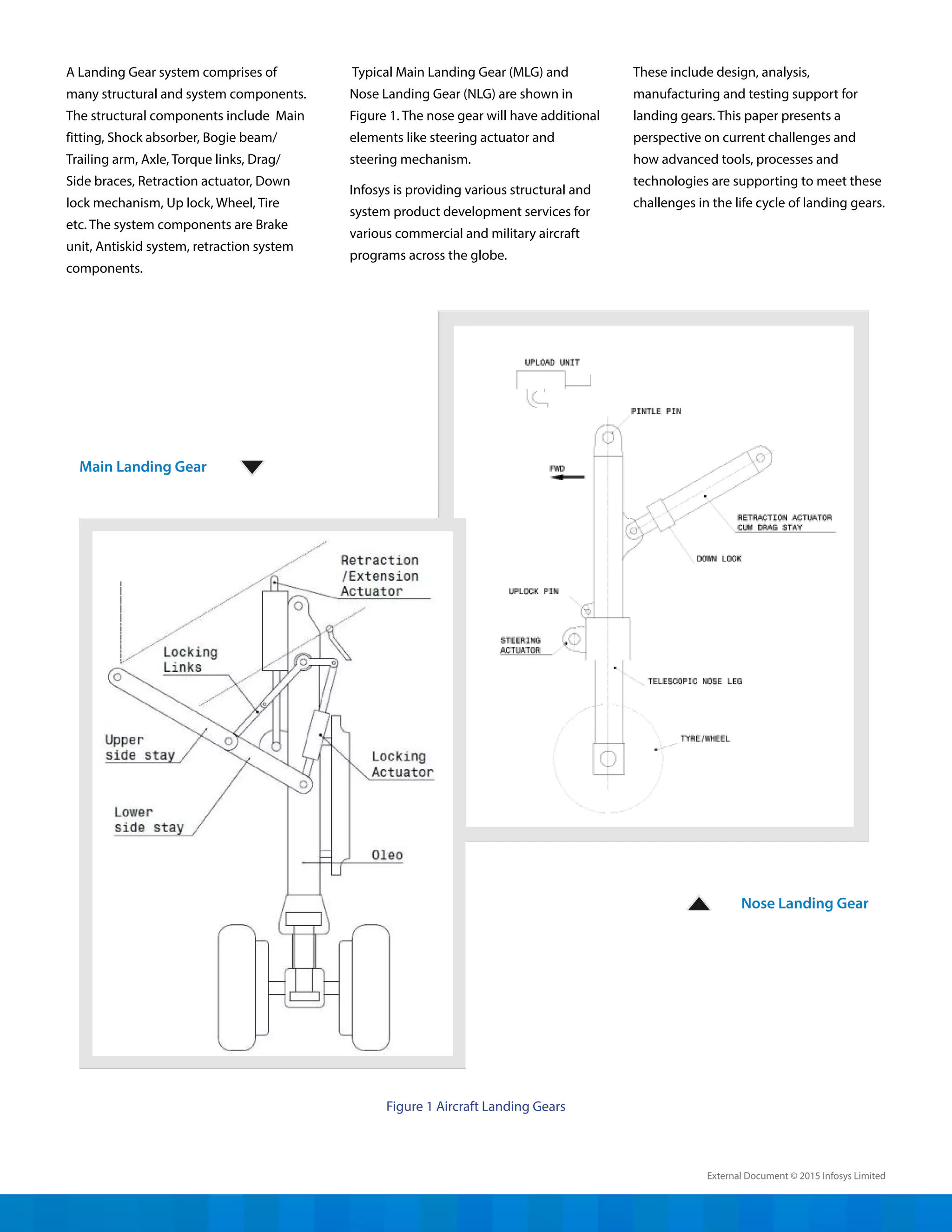
SlideShare a Scribd company logo
Abstract
Landing gear is one of the critical subsystems of an aircraft. The need to design
landing gear with minimum weight, minimum volume, high performance,
improved life and reduced life cycle cost have posed many challenges to landing
gear designers and practitioners. Further it is essential to reduce the landing gear
design and development cycle time while meeting all the regulatory and safety
requirements. Many technologies have been developed over the years to meet
these challenges in design and development of landing gear. This paper presents
a perspective on various stages of landing gear design and development, current
technology landscape and how these technologies are helping us to meet the
challenges involved in the development of landing gear and how they are going to
evolve in future.
- Divakaran V. N., Ravi Kumar G. V. V. and Srinivasa Rao P.
Aircraft Landing Gear Design & Development-
How Advanced Technologies are helping to meet the challenges?
WHITE PAPER
Introduction
Landing Gear system is one of the critical
subsystems of an aircraft and is often
configured along with the aircraft structure
because of its substantial influence on
the aircraft structural configuration itself.
Landing gear detail design is taken up early
in the aircraft design cycle due to its long
product development cycle time. The need
to design landing gear with minimum
weight, minimum volume, reduced life
cycle cost and short development cycle
time, poses many challenges to landing
gear designers and practitioners. These
challenges have to be met by employing
advanced technologies, materials, analysis
methods, processes and production
methods. Various design and analysis tools
have been developed over the years and
new ones are still being developed.
The purpose of the landing gear in an
aircraft is to provide a suspension system
during taxi, take-off and landing. It is
designed to absorb and dissipate the
kinetic energy of landing impact, thereby
reducing the impact loads transmitted
to the airframe. The landing gear also
facilitates braking of the aircraft using
a wheel braking system and provides
directional control of the aircraft on
ground using a wheel steering system. It
is often made retractable to minimize the
aerodynamic drag on the aircraft while
flying.
The landing gear design takes into
account various requirements of strength,
stability, stiffness, ground clearance,
control and damping under all possible
ground attitudes of the aircraft. These
requirements are stipulated by the
Airworthiness Regulations to meet
operational requirements and safety. The
landing gear should occupy minimum
volume in order to reduce the stowage
space requirement in the aircraft. Further,
weight should be at minimum to increase
the performance of the aircraft. The service
life of the landing gears should be same as
that of the aircraft.
External Document © 2015 Infosys Limited
These include design, analysis,
manufacturing and testing support for
landing gears. This paper presents a
perspective on current challenges and
how advanced tools, processes and
technologies are supporting to meet these
challenges in the life cycle of landing gears.
A Landing Gear system comprises of
many structural and system components.
The structural components include Main
fitting, Shock absorber, Bogie beam/
Trailing arm, Axle, Torque links, Drag/
Side braces, Retraction actuator, Down
lock mechanism, Up lock, Wheel, Tire
etc. The system components are Brake
unit, Antiskid system, retraction system
components.
Typical Main Landing Gear (MLG) and
Nose Landing Gear (NLG) are shown in
Figure 1. The nose gear will have additional
elements like steering actuator and
steering mechanism.
Infosys is providing various structural and
system product development services for
various commercial and military aircraft
programs across the globe.
Figure 1 Aircraft Landing Gears
Nose Landing Gear
Main Landing Gear
External Document © 2015 Infosys Limited
Concept Design
The concept design starts with a study of
all design specifications and airworthiness
regulations. A concept is then evolved
while meeting the functional and
regulatory requirements. Major design
drivers are performance, safety, cost,
time frame, technology and resources.
The landing gear location is arrived at
and type of landing gear is selected. The
landing gear geometry is defined along
with kinematics. Steering concepts are also
identified in this phase. The ground loads
are estimated using dynamic simulations
for material selection and preliminary
sizing of components. The actuation
mechanisms and loads are also worked
out in this phase. Various tradeoff studies
are performed to optimize weight, volume
and cost. Based on these trade-off studies a
best concept is selected.
Preliminary Design
In the preliminary design phase, dynamic
simulations are carried out for landing,
take off and retraction kinematics to arrive
at data required for sizing of components
and material selection. Preliminary design
of components is performed and weight
estimates are arrived at.
An Overview of Landing Gear
Design and Development
The landing gear design and integration
process encompasses knowledge of many
engineering disciplines such as structures,
dynamics, kinematics, fluid mechanics and
runway flotation. The geometry, flotation
requirements, mission requirements and
operational requirements of the aircraft
govern the landing gear configuration.
The configuration design includes choice
of number of wheels, tire sizes, pressures,
type of shock absorbers, landing gear
layout, retraction kinematics and bay
geometry design.
Airworthiness regulations play a crucial
role in arriving at the landing gear
configuration, such as sink rate, allowable
load factors and ground maneuvering
conditions, stipulated in the applicable
airworthiness regulations.
Some of these Airworthiness Regulations
are given in Table 1.
Utility and
Aerobatic
Airplanes
Civil
Transport
Airplanes
Military
Aircraft
FAR 23, CS 23, CAR 23
FAR 25, CS 25, CAR 25
US MIL Specifications,
DEF-STAN-970
Aircraft
Type
Regulations/
Specifications
A brief summary of various life cycle stages
of landing gear design and development
are described below:
Table 1: Airworthiness Regulations
External Document © 2015 Infosys Limited
Fatigue tests including impulse fatigue
tests on actuators, are conducted by
block wise loading with sufficient
instrumentation for data acquisition.
Endurance cycling tests are conducted in
special rigs. Environmental tests including
vibration, acceleration, temperature,
altitude, salt spray, sand and dust etc. are
performed.
On- Aircraft Testing
The final integration tests of the landing
gear are carried out after installation on the
aircraft followed by taxi tests, braking and
steering tests. Fine tuning of certain design
parameters are done during this phase.
This is followed by flight testing phase
where the capability of the landing gear is
evaluated.
In- service Evaluation
In -service evaluation includes evaluation
in various types of airfield conditions
and ambient conditions. Feedbacks on
reliability and maintainability results are
taken for further improvements in the
system and data generation.
Detailed Design
In this phase the detailed design of all the
landing gear components is performed
and an integrated landing gear system is
defined with all interfaces and associated
systems. Component loads are estimated
and material selection and sizing are
done in this phase. Reduction in part
count by making closed die forgings
for complex shapes is done through 3D
CAD modeling that enable computer
controlled 3D machining. Dynamic analysis
and simulation is carried out to fine tune
certain design parameters for energy
absorption, shimmy suppression and
retraction/extension. In this phase digital
mock-up of the landing gear is developed
which is essentially the virtual prototype
of the landing gear. All lessons learned
and best practices evolved over the years
are utilized in the detail design to realize a
reliable design.
Stress & Fatigue Analysis
Finite element modeling and analysis and
conventional hand calculation methods
are used for landing gear stress analysis.
Landing gear is designed as a safe life
structure and fatigue analysis methods
are used for prediction of life. Safe life
requirements demand as high as 60,000
landings for a commercial aircraft landing
gear whereas military aircraft requirements
are often not more than 10,000 landings.
Low cycle, high stress fatigue analysis is
employed for landing gear life evaluation.
Damage tolerant design is not practicable
in most of the landing gears because of
the usage of very high strength materials
which have critical flaw sizes too small
to be detected by present day NDT
techniques.
Reliability & Maintainability Analysis
Proper failure mode and effect and
criticality analysis (FMECA) is performed
to assess reliability. Data on failure modes
and failure rate are collected from previous
designs to conduct this analysis and
reliability is predicted before the design
freeze.
Quality, reliability and maintainability
are important to cut down operational
costs and to ensure aircraft availability for
service. The design aims at increased mean
time between failures (MTBF) and reduced
mean time to repair (MTTR). Periodic
preventive maintenance schedules and on-
condition maintenance requirements are
specified as required. Various best practices
evolved are followed in design to ensure
good maintainability.
Health monitoring systems are being
evolved to move towards condition based
maintenance practice from scheduled
maintenance practice, which will lead
to enhanced safety and reduction in
maintenance costs.
Manufacturing & Assembly
The landing gear manufacturing involves
development of many closed die forgings,
machined components from ultra-high
strength steels, titanium and aluminum
alloys. Precision tolerances are required
for components like actuator cylinder,
piston, shock absorber parts and axle. Heat
treatment of parts is performed after rough
machining followed by final machining,
plating and painting. Reliability of the
product is enhanced through stringent
quality assurance requirements.
Qualification Testing
The qualification testing of landing gears
involves functional tests, structural tests
for strength, stiffness and fatigue life tests,
and environmental tests. Platform drop
tests are conducted on rigs with load cell
platform, wheel spinning facility and lift
simulation devices to verify shock absorber
performance. For structural strength tests
of the landing gear, loads are applied
through loading actuators in required
directions and strain data is acquired
through strain gauging.
External Document © 2015 Infosys Limited
The semi-active system works by varying
the viscosity of the fluid as required for
the damping. In active control it is aimed
to control the stiffness and damping
characteristic so as to control the ground
loads.
For higher performance of actuation
systems for landing gear, nose wheel
steering and brakes, alternate systems
are being evolved. Use of hydraulic
systems in place of mechanical systems
or use of electric systems in place of
hydraulic systems is studied for optimizing
performance. Use of electronic control
also enhances the performance of control
systems.
Life
Long life and minimum maintenance
requirements are vital for reduction in
operating and maintenance costs while
minimizing the overall life cycle cost.
This dictates the choice of materials,
its corrosion properties and fatigue
properties.
Development Time
The landing gear design is iterative
involving trade-off studies between
various configurations and their impact on
weight and cost benefits.
Challenges in Landing Gear
Design & Development
The need to design landing gear with
minimum weight, minimum volume, high
performance, improved life and reduced
life cycle cost poses many challenges.
Further, the design and development cycle
time of landing gear should be compressed
to reduce costs and to bring the product
to market faster. These challenges are
met, while adhering to all regulatory
requirements of safety, by employing
advanced technologies, materials,
processes, analysis and production
methods.
Weight
Landing gear is heavily loaded structure.
Its weight varies from 3% of aircraft all-
up weight for a fixed type to about 6%
for a retractable type landing gear. The
challenge is to reduce the weight of the
landing gear without compromising on
its functional, operational, performance,
safety and maintenance requirements.
This is made possible by using materials of
higher strength, fracture toughness and
fatigue properties and by making correct
choice for each application. These materials
include ultra-high strength alloy steels,
corrosion resistant steels, titanium alloys
and high strength aluminum alloys.
Volume
Space is one of the most important
constraints within which an aircraft
component needs to be designed,
especially in a military aircraft. A retractable
landing gear contains more components
and mechanisms than a fixed landing gear.
By proper choice of material and design of
the geometry of mechanism it is ensured
that requirement of retracted volume is
brought down to a minimum.
Performance
High performance of the landing gear is
expected in order to reduce the ground
loads transmitted to the airframe. This is
ensured by accurate dynamic analysis and
simulation to arrive at key performance
characteristics like orifice sizing, air and
oil volumes. Efficiencies as high as 85%
to 90% are achievable in landing energy
absorption with passive orifice damping
with proper metering pin or valve system.
Further, the pursuit for high performance
leads to semi-active or active control
shock absorber systems. It is found that
substantial damage is caused due to
loads in taxi phase and performance
improvement during taxi phase requires
either semi-active or active damping
systems.
External Document © 2015 Infosys Limited
This usually takes substantial time and
effort. It is essential to reduce this product
development cycle time by automating
the design process using CAD/CAE/
CAM tools. These tools help reducing
the development time through virtual
prototyping which can be evaluated before
testing on actual prototypes. Further,
Knowledge Based Engineering (KBE)
concepts and tools are playing important
role in reducing development cycle time.
Life cycle cost
Use of advanced technologies like health
management systems and maintenance
philosophies helps in reducing the life
cycle costs. Design for condition based
maintenance instead of scheduled
maintenance is one such trend and is
compatible with health management
systems.
Landing Gear Technologies
Landing gear technologies are
continuously evolving to meet the
challenges of functional and non-
functional requirements. Some of these
important technologies are presented
below:
Steering System
Steering control systems are moving
towards electronic control systems
replacing hydro-mechanical systems. The
main advantage with electronic control
system is its accuracy and its ability to
incorporate changes in design parameters
like steering rate and steering ratio with
ease.
Actuation System
In actuation systems, more electric or
all electric systems are replacing the
conventional hydraulic systems. The
electric systems offered today have
become weight competitive with use of
brushless high power motors. Further,
electric systems help to overcome
problems of leakage and fire hazard.
Brake system
Electronically controlled antiskid brake
management systems are replacing old
mechanical or electric antiskid systems.
Electronic systems are more efficient and
trouble free.
Tires
Radial tire is one of the advanced
technologies employed in aircraft for the
past 25 years. Landing gear radial tires
offer lighter tires with longer life compared
to bias ply tires.
Up-locks
Hydro-mechanical locking systems
and proximity switches are replacing
mechanical locks and micro-switches. They
have higher reliability.
Materials
Composites are being used in some
components of landing gear because
of their superior specific strength and
stiffness properties. Cost used to be
one factor against their favor, which is
now being overcome with improved
manufacturing techniques. Ultra-high
strength steels are used due to its
high strength to weight ratio and size
advantage.
The choice of material for a landing gear
component is decided depending on its
application and this requires trade off
studies of strength, stiffness and cost to
arrive at the optimal choice. Fatigue and
fracture toughness properties and aspects
like protection against stress corrosion,
wear, reliability in service etc. are other
considerations in the selection of material
for the landing gear.
Carbon composite brake disc offers
reduced weight, longer life and
maintenance free wheel brakes thereby
reducing the cost per landing.
Corrosion protection
Good corrosion protection is important for
the landing gear components as they are
susceptible for easy environment attack.
Apart from normal electrolytic finishes like
cadmium plating, hard chromium plating,
HVOF etc. epoxy or polyurethane primer
and polyurethane top coats are applied
for the exposed landing gear parts. Use
of corrosion resistant materials is also
becoming increasingly popular.
External Document © 2015 Infosys Limited
CAX Technologies
Many commercially available CAD/
CAM/CAE/CFD and Dynamic Simulation
software tools are used in the design
and development of landing gear. These
tools have helped in virtual product
development of landing gear before actual
prototype is being fabricated. These help to
improve designs with reduced cycle time
and cost. Few of them include
Knowledge Based Engineering (KBE)
Many Knowledge Based Engineering
(KBE) tools and information intelligence
tools are being developed and used by
landing gear designers to automate many
engineering processes while retaining
company specific knowledge. These tools
leads to drastic reduction in development
cycle time, reduction in human errors,
ability to redesign iteratively and capturing
organizational knowledge. Few of these
tools include
•	 Tools for selection of number of tires
and pressures taking the ground
flotation requirement
•	 Wheel/Brake sizing tools
•	 Ground load estimation tools
Dynamic Simulation
Dynamic simulation helps to predict
the performance of a component or
assembly. The results of these simulations
will be more accurate compared to hand
calculations. These simulations help in
handling large number of studies in short
time.
The landing gear shock absorber
performance is evaluated by a dynamic
simulation of the landing and taxiing. This
takes into account the hydraulic damping,
air spring characteristics and friction effects
and structural flexibility in the landing gear.
Using the computer models developed
for this purpose the shock absorber
parameters are optimized to maximize
its efficiency and peak reaction behavior.
This helps in preliminary estimation of
impact loads and taxi loads to arrive at
the sizing of the landing gear elements for
use in geometric modeling and kinematic
analysis.
The retraction/extension kinematics and
actuation are also simulated by dynamic
modeling of the hydraulic actuation and
CFD analysis to arrive at the actuator sizing.
The CFD analysis is used to arrive at the
aerodynamic loads acting on the landing
gear during retraction/extension process.
Thus simulations helps to mitigate the risk
in the design and development process,
which otherwise requires iterations after
extensive and expensive testing.
Shimmy oscillations are a perennial
problem in design and operation of
landing gears and proper analysis is
required to control/overcome it.
Adequate torsional stiffness and damping
are required to ensure a shimmy free
landing gear. Mathematical models are
used to predict onset of shimmy and to
design damping devices to control the
shimmy oscillations.
Health monitoring
Landing gear is a maintenance intensive
system of the aircraft next to only engine.
Health monitoring of landing gear is
gaining importance as suitable sensors
and processing units are available
today. Wireless sensor network and RFID
technologies are being employed in
health management of aircraft systems
and structures including landing gear.
Health monitoring not only improves
the safety and reduces both operational
and maintenance costs, but also helps
in extending the life of the landing gear
beyond designed service life.
CAD Tools
CATIA V5, UG, Solid
works,
CAE Tools
NASTRAN, ABAQUS,
ANSYS, Hypermesh,
Optistruct
Dynamic
Simulation
Tools
MATLAB, SIMULINK,
ADAMS
CFD Tools
Flow works, Ansys-
Fluent, Ansys-CFX,
Star –CD
Kinematics
CATIA V5, UG, Solid
works,
Table 2: CAX Tools
•	 Tools to compute axle travels
requirements
•	 Tools to analyze retraction actuation
•	 Shock absorber performance
optimization tools
•	 Rake and Trail requirements analysis
tools
•	 Shimmy analysis tools
External Document © 2015 Infosys Limited
Summary of Future Landing
Gear Technologies
In future landing gear design and
development will use high strength
materials, active damping systems and
accurate load estimation techniques.
Active damping system aims at reducing
taxi loads which are known to be a very
significant contributor of fatigue failure.
It is found that taxi damages are close to
50% of total damages in a commercial
aircraft. Future is also expected to witness
increased use of composite materials for
many components. In actuation system
smart sensors that are more durable and
energy efficient and will drive towards
condition based maintenance philosophy.
Big Data technologies, advanced
analytics techniques and tools will help
in capturing and reusing the operational
and maintenance data providing greater
insights. This will help in reducing the
maintenance and operational costs
drastically. Crashworthy landing gears
for use on helicopters pose additional
challenges in absorbing large quantities of
energy resulting from a crash. This includes
fuse orifices and additional chambers in
the oleo.
design,‘more electric’or‘ all electric’
concepts are gaining momentum to
replace hydraulic actuation, which is
known for its problems of leaks and
flammability. Electric actuation systems
are becoming weight competitive
enough to displace the old hydraulic
actuation systems. Carbon composite
brake materials have become a mature
technology like the radial tires and will be
used widely in future landing gears. CAX
and KBE will be used more effectively. In
addition, integrated health management
systems for diagnostic and prognostic
analysis will employ next generation
Table 3: How Technologies Help to meet Challenges?
External Document © 2015 Infosys Limited
Conclusions
The need to design landing gear with
minimum weight, minimum volume,
high performance, improved life and
reduced life cycle cost have posed many
challenges to landing gear designers
and practitioners. Further it is essential
to reduce the landing gear design and
development cycle time while meeting all
the safety and regulatory requirements.
Many technologies have been developed
over the years to meet the challenges of
landing gear design and development.
materials, analysis methods, processes
and production methods. By applying
functional simulation and developing
design tools, the development time and
cost are reduced considerably. Use of
higher strength materials, composites, and
technologies like active damping control,
electric systems, along with CAX, KBE and
health monitoring technologies will steer
the landing gear design in the days to
come.
These technologies have matured over
the years and widely used in the current
landing gear system and new technologies
will continue to evolve in future.
The future landing gear design for
aircraft poses many new challenges in
configuration design, use of materials,
design and analysis methods. These
challenges can be met, while adhering to
all regulatory requirements of safety, by
employing advanced technologies,
Material Selection Ultra high strength metallic materials, advanced composites, Radial tires, Carbon composite brake discs
Design Life Cycle Stage Technology Trend
Design 3D modeling and design, Simulation, virtual prototyping, KBE
Systems All electric actuation, Electronic control
Analysis FEA, Fatigue and Damage Tolerance Analysis
Testing More Accurate systems for strain gauging and data acquisition
Maintenance Health monitoring, Wireless Sensor Networks, RFID technologies
Reliability Accurate failure rates based on feedback data from field
Table 4: Technology trends for future landing design
External Document © 2015 Infosys Limited
About authors
Divakaran V.N.
is a Consultant with Infosys since December, 2006. Prior to this, he was Head of Design (Mechanical Systems) at Hindustan
Aeronautics Ltd in its Aircraft Research and Design Centre. At HAL he has over 35 years of experience in design and
development of landing gears and other mechanical systems, working in military aircraft programs like Light Combat
Aircraft, Advanced Light Helicopter, Intermediate Jet Trainer and civil Light Transport Aircraft. He has two patents
in mechanical design. He obtained degree in mechanical engineering from NIT, Calicut and underwent 9 months of
institutional training in Aeronautics at Indian Institute of Science, Bangalore.
Dr Ravikumar, G.V.V.
is Senior Principal and Head Advanced Engineering Group (AEG) brings together 21 years of research and industrial
experience in Aircraft Industry. His areas of interest include Aircraft Structures, Knowledge Based Engineering, Composites
and Structural Health Monitoring. He authored more than 30 technical papers in various journals/conferences/white papers
and filed a patent. He worked on various prestigious engineering design and development, KBE tool development projects
for both military and commercial aircraft programs including Indian light combat aircraft (LCA). He obtained his doctoral
degree in Applied Mechanics from IIT Delhi. He worked in Tata Research Design and Development Center (TRDDC), Pune
and Aeronautical Development Agency (ADA) Bangalore prior to joining Infosys.
Srinivasa Rao Patnala
is a Practice Manager brings about 23 years of industry experience with focused aerospace experience for about 20 years.
His technical area of expertise is in the stress analysis of metallic aero structures and finite element analysis. He led several
projects on design and development of structural systems for global commercial aircraft prorams. He has the distinction
of perfoming a technical signatory role in one of the European Aircraft type certification program. He obtained his masters
degree in Mechanical Engineering from Indian Institute of Science, Bangalore. He has worked on missle structures during
his initial 8 years of stint at Defence Research and Development Laboratory (DRDL), Hyderabad.
Acknowledgements
The authors would like to thank senior management of engineering services practice of Infosys for their continuous support and
encouragement.
External Document © 2015 Infosys Limited
© 2015 Infosys Limited, Bangalore, India. All Rights Reserved. Infosys believes the information in this document is accurate as of its publication date; such information is subject to change without notice.
Infosys acknowledges the proprietary rights of other companies to the trademarks, product names and such other intellectual property rights mentioned in this document. Except as expressly permitted,
neither this documentation nor any part of it may be reproduced, stored in a retrieval system, or transmitted in any form or by any means, electronic, mechanical, printing, photocopying, recording or
otherwise, without the prior permission of Infosys Limited and/ or any named intellectual property rights holders under this document.
About Infosys
Infosys is a global leader in consulting, technology, outsourcing and next-generation services. We enable clients, in more than 50 countries, to stay a
step ahead of emerging business trends and outperform the competition. We help them transform and thrive in a changing world by co-creating
breakthrough solutions that combine strategic insights and execution excellence.
Visit www.infosys.com to see how Infosys (NYSE: INFY), with US$8.25 B in annual revenues and 165,000+ employees, is helping enterprises renew
themselves while also creating new avenues to generate value.
For more information, contact askus@infosys.com www.infosys.com

More Related Content

What's hot

Landing Gear Project Final Report
Landing Gear Project Final ReportLanding Gear Project Final Report
Landing Gear Project Final ReportKevin Osman
 
Aircraft Design Project 1
Aircraft Design Project 1Aircraft Design Project 1
Aircraft Design Project 1chiraggoyal59
 
Longitudinal static stability of boeing 737 max 8
Longitudinal static stability of boeing 737 max 8Longitudinal static stability of boeing 737 max 8
Longitudinal static stability of boeing 737 max 8Lahiru Dilshan
 
Swept wing configuration
Swept wing configuration Swept wing configuration
Swept wing configuration Buddhikaaero
 
Final Report -Aircraft Design
Final Report -Aircraft DesignFinal Report -Aircraft Design
Final Report -Aircraft DesignThomas Spisak
 
Introduction to Aircraft Structural Design
Introduction to Aircraft Structural DesignIntroduction to Aircraft Structural Design
Introduction to Aircraft Structural DesignSuthan Rajendran
 
Aircraft Wing
Aircraft Wing Aircraft Wing
Aircraft Wing Vishal Vyas
 
Aerodynamics slide
Aerodynamics slideAerodynamics slide
Aerodynamics slideLinda Jaquiline
 
Aircraft Systems and Instruments
Aircraft Systems and InstrumentsAircraft Systems and Instruments
Aircraft Systems and InstrumentsVarun Karthikeyan
 
Fuselage structures
Fuselage structuresFuselage structures
Fuselage structuresalpha_sherdil
 
PPT - BOEING - FRANKFINN ALUVA
PPT - BOEING - FRANKFINN ALUVAPPT - BOEING - FRANKFINN ALUVA
PPT - BOEING - FRANKFINN ALUVAbilbinp
 
Basic aircraft structure
Basic aircraft structureBasic aircraft structure
Basic aircraft structurenyinyilay
 
Flight control systems
Flight control systemsFlight control systems
Flight control systemsTalha Karim
 
SAE 2015 Final Report
SAE 2015 Final ReportSAE 2015 Final Report
SAE 2015 Final ReportAbhiram Doddi
 
Basic aircraft structure
Basic aircraft structureBasic aircraft structure
Basic aircraft structurejignesh prajapati
 

What's hot (20)

Landing Gear Project Final Report
Landing Gear Project Final ReportLanding Gear Project Final Report
Landing Gear Project Final Report
 
Aircraft Design Project 1
Aircraft Design Project 1Aircraft Design Project 1
Aircraft Design Project 1
 
Aircraft wing
Aircraft wingAircraft wing
Aircraft wing
 
Flight Basics
Flight BasicsFlight Basics
Flight Basics
 
Basics of Aerodynamics
Basics of AerodynamicsBasics of Aerodynamics
Basics of Aerodynamics
 
Longitudinal static stability of boeing 737 max 8
Longitudinal static stability of boeing 737 max 8Longitudinal static stability of boeing 737 max 8
Longitudinal static stability of boeing 737 max 8
 
Swept wing configuration
Swept wing configuration Swept wing configuration
Swept wing configuration
 
Final Report -Aircraft Design
Final Report -Aircraft DesignFinal Report -Aircraft Design
Final Report -Aircraft Design
 
Introduction to Aircraft Structural Design
Introduction to Aircraft Structural DesignIntroduction to Aircraft Structural Design
Introduction to Aircraft Structural Design
 
Aircraft Wing
Aircraft Wing Aircraft Wing
Aircraft Wing
 
Aerodynamics slide
Aerodynamics slideAerodynamics slide
Aerodynamics slide
 
Aircraft Systems and Instruments
Aircraft Systems and InstrumentsAircraft Systems and Instruments
Aircraft Systems and Instruments
 
Aircraft parts
Aircraft partsAircraft parts
Aircraft parts
 
Fuselage structures
Fuselage structuresFuselage structures
Fuselage structures
 
Theory of flight final
Theory of flight finalTheory of flight final
Theory of flight final
 
PPT - BOEING - FRANKFINN ALUVA
PPT - BOEING - FRANKFINN ALUVAPPT - BOEING - FRANKFINN ALUVA
PPT - BOEING - FRANKFINN ALUVA
 
Basic aircraft structure
Basic aircraft structureBasic aircraft structure
Basic aircraft structure
 
Flight control systems
Flight control systemsFlight control systems
Flight control systems
 
SAE 2015 Final Report
SAE 2015 Final ReportSAE 2015 Final Report
SAE 2015 Final Report
 
Basic aircraft structure
Basic aircraft structureBasic aircraft structure
Basic aircraft structure
 

Similar to landing-gear-design-and-development

Fps report landing gear
Fps report landing gearFps report landing gear
Fps report landing gearHarsh Yadav
 
IRJET- Numerical Analysis of Nose Landing Gear System
IRJET-  	  Numerical Analysis of Nose Landing Gear SystemIRJET-  	  Numerical Analysis of Nose Landing Gear System
IRJET- Numerical Analysis of Nose Landing Gear SystemIRJET Journal
 
digital avionics systems
digital avionics systemsdigital avionics systems
digital avionics systemsrammohan ijjada
 
Computational Analysis of the Aerodynamic Performance of NACA 4412 and NACA 2...
Computational Analysis of the Aerodynamic Performance of NACA 4412 and NACA 2...Computational Analysis of the Aerodynamic Performance of NACA 4412 and NACA 2...
Computational Analysis of the Aerodynamic Performance of NACA 4412 and NACA 2...IRJET Journal
 
Structural Analysis and Optimization for Spar Beam of an Aircraft
Structural Analysis and Optimization for Spar Beam of an AircraftStructural Analysis and Optimization for Spar Beam of an Aircraft
Structural Analysis and Optimization for Spar Beam of an AircraftIRJET Journal
 
IRJET- Topology Optimization of a Lower Barrel in Nose Landing Gear
IRJET- Topology Optimization of a Lower Barrel in Nose Landing GearIRJET- Topology Optimization of a Lower Barrel in Nose Landing Gear
IRJET- Topology Optimization of a Lower Barrel in Nose Landing GearIRJET Journal
 
IRJET- Flow Simulation for Aircraft using Computational Fluid Dynamics
IRJET- Flow Simulation for Aircraft using Computational Fluid DynamicsIRJET- Flow Simulation for Aircraft using Computational Fluid Dynamics
IRJET- Flow Simulation for Aircraft using Computational Fluid DynamicsIRJET Journal
 
Avionics
AvionicsAvionics
AvionicsBrightlin3
 
Transformative Roles Of Global Engineering Partners
Transformative Roles Of Global Engineering PartnersTransformative Roles Of Global Engineering Partners
Transformative Roles Of Global Engineering Partnersgiancarlo
 
AIRCRAFT DESIGN PROJECT -I FIGHTER JETS A PROJECT REPORT
AIRCRAFT DESIGN PROJECT -I FIGHTER JETS A PROJECT REPORTAIRCRAFT DESIGN PROJECT -I FIGHTER JETS A PROJECT REPORT
AIRCRAFT DESIGN PROJECT -I FIGHTER JETS A PROJECT REPORTDon Dooley
 
Aircraft Resume New-1
Aircraft Resume New-1Aircraft Resume New-1
Aircraft Resume New-1Tulasiram M
 
IRJET- Design and Fluid Flow Analysis of F1 Race Car
IRJET- Design and Fluid Flow Analysis of F1 Race CarIRJET- Design and Fluid Flow Analysis of F1 Race Car
IRJET- Design and Fluid Flow Analysis of F1 Race CarIRJET Journal
 
LCAS Presentation
LCAS PresentationLCAS Presentation
LCAS PresentationSruli Weinreb
 
High_Voltage_Design_Brief
High_Voltage_Design_BriefHigh_Voltage_Design_Brief
High_Voltage_Design_BriefLansing Wei
 
IRJET- Improving the Performance of all Terrain Vehicle
IRJET- 	  Improving the Performance of all Terrain VehicleIRJET- 	  Improving the Performance of all Terrain Vehicle
IRJET- Improving the Performance of all Terrain VehicleIRJET Journal
 
Additive manufacturing-for-the-aircraft-industry-a-review-2329-6542-1000214
Additive manufacturing-for-the-aircraft-industry-a-review-2329-6542-1000214Additive manufacturing-for-the-aircraft-industry-a-review-2329-6542-1000214
Additive manufacturing-for-the-aircraft-industry-a-review-2329-6542-1000214deepak kumar
 
Flow Anlaysis on Hal Tejas Aircraft using Computational Fluid Dynamics with D...
Flow Anlaysis on Hal Tejas Aircraft using Computational Fluid Dynamics with D...Flow Anlaysis on Hal Tejas Aircraft using Computational Fluid Dynamics with D...
Flow Anlaysis on Hal Tejas Aircraft using Computational Fluid Dynamics with D...IJAEMSJORNAL
 

Similar to landing-gear-design-and-development (20)

Fps report landing gear
Fps report landing gearFps report landing gear
Fps report landing gear
 
IRJET- Numerical Analysis of Nose Landing Gear System
IRJET-  	  Numerical Analysis of Nose Landing Gear SystemIRJET-  	  Numerical Analysis of Nose Landing Gear System
IRJET- Numerical Analysis of Nose Landing Gear System
 
digital avionics systems
digital avionics systemsdigital avionics systems
digital avionics systems
 
Computational Analysis of the Aerodynamic Performance of NACA 4412 and NACA 2...
Computational Analysis of the Aerodynamic Performance of NACA 4412 and NACA 2...Computational Analysis of the Aerodynamic Performance of NACA 4412 and NACA 2...
Computational Analysis of the Aerodynamic Performance of NACA 4412 and NACA 2...
 
Structural Analysis and Optimization for Spar Beam of an Aircraft
Structural Analysis and Optimization for Spar Beam of an AircraftStructural Analysis and Optimization for Spar Beam of an Aircraft
Structural Analysis and Optimization for Spar Beam of an Aircraft
 
IRJET- Topology Optimization of a Lower Barrel in Nose Landing Gear
IRJET- Topology Optimization of a Lower Barrel in Nose Landing GearIRJET- Topology Optimization of a Lower Barrel in Nose Landing Gear
IRJET- Topology Optimization of a Lower Barrel in Nose Landing Gear
 
IRJET- Flow Simulation for Aircraft using Computational Fluid Dynamics
IRJET- Flow Simulation for Aircraft using Computational Fluid DynamicsIRJET- Flow Simulation for Aircraft using Computational Fluid Dynamics
IRJET- Flow Simulation for Aircraft using Computational Fluid Dynamics
 
Avionics
AvionicsAvionics
Avionics
 
Transformative Roles Of Global Engineering Partners
Transformative Roles Of Global Engineering PartnersTransformative Roles Of Global Engineering Partners
Transformative Roles Of Global Engineering Partners
 
AIRCRAFT DESIGN PROJECT -I FIGHTER JETS A PROJECT REPORT
AIRCRAFT DESIGN PROJECT -I FIGHTER JETS A PROJECT REPORTAIRCRAFT DESIGN PROJECT -I FIGHTER JETS A PROJECT REPORT
AIRCRAFT DESIGN PROJECT -I FIGHTER JETS A PROJECT REPORT
 
Aircraft Resume New-1
Aircraft Resume New-1Aircraft Resume New-1
Aircraft Resume New-1
 
IRJET- Design and Fluid Flow Analysis of F1 Race Car
IRJET- Design and Fluid Flow Analysis of F1 Race CarIRJET- Design and Fluid Flow Analysis of F1 Race Car
IRJET- Design and Fluid Flow Analysis of F1 Race Car
 
LCAS Presentation
LCAS PresentationLCAS Presentation
LCAS Presentation
 
High_Voltage_Design_Brief
High_Voltage_Design_BriefHigh_Voltage_Design_Brief
High_Voltage_Design_Brief
 
Santosh bhatt
Santosh bhattSantosh bhatt
Santosh bhatt
 
IRJET- Improving the Performance of all Terrain Vehicle
IRJET- 	  Improving the Performance of all Terrain VehicleIRJET- 	  Improving the Performance of all Terrain Vehicle
IRJET- Improving the Performance of all Terrain Vehicle
 
Additive manufacturing-for-the-aircraft-industry-a-review-2329-6542-1000214
Additive manufacturing-for-the-aircraft-industry-a-review-2329-6542-1000214Additive manufacturing-for-the-aircraft-industry-a-review-2329-6542-1000214
Additive manufacturing-for-the-aircraft-industry-a-review-2329-6542-1000214
 
seminar ppt.pptx
seminar ppt.pptxseminar ppt.pptx
seminar ppt.pptx
 
Flow Anlaysis on Hal Tejas Aircraft using Computational Fluid Dynamics with D...
Flow Anlaysis on Hal Tejas Aircraft using Computational Fluid Dynamics with D...Flow Anlaysis on Hal Tejas Aircraft using Computational Fluid Dynamics with D...
Flow Anlaysis on Hal Tejas Aircraft using Computational Fluid Dynamics with D...
 
Presentation of Engineering Services
Presentation of Engineering ServicesPresentation of Engineering Services
Presentation of Engineering Services
 

landing-gear-design-and-development

  • 1. Abstract Landing gear is one of the critical subsystems of an aircraft. The need to design landing gear with minimum weight, minimum volume, high performance, improved life and reduced life cycle cost have posed many challenges to landing gear designers and practitioners. Further it is essential to reduce the landing gear design and development cycle time while meeting all the regulatory and safety requirements. Many technologies have been developed over the years to meet these challenges in design and development of landing gear. This paper presents a perspective on various stages of landing gear design and development, current technology landscape and how these technologies are helping us to meet the challenges involved in the development of landing gear and how they are going to evolve in future. - Divakaran V. N., Ravi Kumar G. V. V. and Srinivasa Rao P. Aircraft Landing Gear Design & Development- How Advanced Technologies are helping to meet the challenges? WHITE PAPER
  • 2. Introduction Landing Gear system is one of the critical subsystems of an aircraft and is often configured along with the aircraft structure because of its substantial influence on the aircraft structural configuration itself. Landing gear detail design is taken up early in the aircraft design cycle due to its long product development cycle time. The need to design landing gear with minimum weight, minimum volume, reduced life cycle cost and short development cycle time, poses many challenges to landing gear designers and practitioners. These challenges have to be met by employing advanced technologies, materials, analysis methods, processes and production methods. Various design and analysis tools have been developed over the years and new ones are still being developed. The purpose of the landing gear in an aircraft is to provide a suspension system during taxi, take-off and landing. It is designed to absorb and dissipate the kinetic energy of landing impact, thereby reducing the impact loads transmitted to the airframe. The landing gear also facilitates braking of the aircraft using a wheel braking system and provides directional control of the aircraft on ground using a wheel steering system. It is often made retractable to minimize the aerodynamic drag on the aircraft while flying. The landing gear design takes into account various requirements of strength, stability, stiffness, ground clearance, control and damping under all possible ground attitudes of the aircraft. These requirements are stipulated by the Airworthiness Regulations to meet operational requirements and safety. The landing gear should occupy minimum volume in order to reduce the stowage space requirement in the aircraft. Further, weight should be at minimum to increase the performance of the aircraft. The service life of the landing gears should be same as that of the aircraft. External Document © 2015 Infosys Limited
  • 3. These include design, analysis, manufacturing and testing support for landing gears. This paper presents a perspective on current challenges and how advanced tools, processes and technologies are supporting to meet these challenges in the life cycle of landing gears. A Landing Gear system comprises of many structural and system components. The structural components include Main fitting, Shock absorber, Bogie beam/ Trailing arm, Axle, Torque links, Drag/ Side braces, Retraction actuator, Down lock mechanism, Up lock, Wheel, Tire etc. The system components are Brake unit, Antiskid system, retraction system components. Typical Main Landing Gear (MLG) and Nose Landing Gear (NLG) are shown in Figure 1. The nose gear will have additional elements like steering actuator and steering mechanism. Infosys is providing various structural and system product development services for various commercial and military aircraft programs across the globe. Figure 1 Aircraft Landing Gears Nose Landing Gear Main Landing Gear External Document © 2015 Infosys Limited
  • 4. Concept Design The concept design starts with a study of all design specifications and airworthiness regulations. A concept is then evolved while meeting the functional and regulatory requirements. Major design drivers are performance, safety, cost, time frame, technology and resources. The landing gear location is arrived at and type of landing gear is selected. The landing gear geometry is defined along with kinematics. Steering concepts are also identified in this phase. The ground loads are estimated using dynamic simulations for material selection and preliminary sizing of components. The actuation mechanisms and loads are also worked out in this phase. Various tradeoff studies are performed to optimize weight, volume and cost. Based on these trade-off studies a best concept is selected. Preliminary Design In the preliminary design phase, dynamic simulations are carried out for landing, take off and retraction kinematics to arrive at data required for sizing of components and material selection. Preliminary design of components is performed and weight estimates are arrived at. An Overview of Landing Gear Design and Development The landing gear design and integration process encompasses knowledge of many engineering disciplines such as structures, dynamics, kinematics, fluid mechanics and runway flotation. The geometry, flotation requirements, mission requirements and operational requirements of the aircraft govern the landing gear configuration. The configuration design includes choice of number of wheels, tire sizes, pressures, type of shock absorbers, landing gear layout, retraction kinematics and bay geometry design. Airworthiness regulations play a crucial role in arriving at the landing gear configuration, such as sink rate, allowable load factors and ground maneuvering conditions, stipulated in the applicable airworthiness regulations. Some of these Airworthiness Regulations are given in Table 1. Utility and Aerobatic Airplanes Civil Transport Airplanes Military Aircraft FAR 23, CS 23, CAR 23 FAR 25, CS 25, CAR 25 US MIL Specifications, DEF-STAN-970 Aircraft Type Regulations/ Specifications A brief summary of various life cycle stages of landing gear design and development are described below: Table 1: Airworthiness Regulations External Document © 2015 Infosys Limited
  • 5. Fatigue tests including impulse fatigue tests on actuators, are conducted by block wise loading with sufficient instrumentation for data acquisition. Endurance cycling tests are conducted in special rigs. Environmental tests including vibration, acceleration, temperature, altitude, salt spray, sand and dust etc. are performed. On- Aircraft Testing The final integration tests of the landing gear are carried out after installation on the aircraft followed by taxi tests, braking and steering tests. Fine tuning of certain design parameters are done during this phase. This is followed by flight testing phase where the capability of the landing gear is evaluated. In- service Evaluation In -service evaluation includes evaluation in various types of airfield conditions and ambient conditions. Feedbacks on reliability and maintainability results are taken for further improvements in the system and data generation. Detailed Design In this phase the detailed design of all the landing gear components is performed and an integrated landing gear system is defined with all interfaces and associated systems. Component loads are estimated and material selection and sizing are done in this phase. Reduction in part count by making closed die forgings for complex shapes is done through 3D CAD modeling that enable computer controlled 3D machining. Dynamic analysis and simulation is carried out to fine tune certain design parameters for energy absorption, shimmy suppression and retraction/extension. In this phase digital mock-up of the landing gear is developed which is essentially the virtual prototype of the landing gear. All lessons learned and best practices evolved over the years are utilized in the detail design to realize a reliable design. Stress & Fatigue Analysis Finite element modeling and analysis and conventional hand calculation methods are used for landing gear stress analysis. Landing gear is designed as a safe life structure and fatigue analysis methods are used for prediction of life. Safe life requirements demand as high as 60,000 landings for a commercial aircraft landing gear whereas military aircraft requirements are often not more than 10,000 landings. Low cycle, high stress fatigue analysis is employed for landing gear life evaluation. Damage tolerant design is not practicable in most of the landing gears because of the usage of very high strength materials which have critical flaw sizes too small to be detected by present day NDT techniques. Reliability & Maintainability Analysis Proper failure mode and effect and criticality analysis (FMECA) is performed to assess reliability. Data on failure modes and failure rate are collected from previous designs to conduct this analysis and reliability is predicted before the design freeze. Quality, reliability and maintainability are important to cut down operational costs and to ensure aircraft availability for service. The design aims at increased mean time between failures (MTBF) and reduced mean time to repair (MTTR). Periodic preventive maintenance schedules and on- condition maintenance requirements are specified as required. Various best practices evolved are followed in design to ensure good maintainability. Health monitoring systems are being evolved to move towards condition based maintenance practice from scheduled maintenance practice, which will lead to enhanced safety and reduction in maintenance costs. Manufacturing & Assembly The landing gear manufacturing involves development of many closed die forgings, machined components from ultra-high strength steels, titanium and aluminum alloys. Precision tolerances are required for components like actuator cylinder, piston, shock absorber parts and axle. Heat treatment of parts is performed after rough machining followed by final machining, plating and painting. Reliability of the product is enhanced through stringent quality assurance requirements. Qualification Testing The qualification testing of landing gears involves functional tests, structural tests for strength, stiffness and fatigue life tests, and environmental tests. Platform drop tests are conducted on rigs with load cell platform, wheel spinning facility and lift simulation devices to verify shock absorber performance. For structural strength tests of the landing gear, loads are applied through loading actuators in required directions and strain data is acquired through strain gauging. External Document © 2015 Infosys Limited
  • 6. The semi-active system works by varying the viscosity of the fluid as required for the damping. In active control it is aimed to control the stiffness and damping characteristic so as to control the ground loads. For higher performance of actuation systems for landing gear, nose wheel steering and brakes, alternate systems are being evolved. Use of hydraulic systems in place of mechanical systems or use of electric systems in place of hydraulic systems is studied for optimizing performance. Use of electronic control also enhances the performance of control systems. Life Long life and minimum maintenance requirements are vital for reduction in operating and maintenance costs while minimizing the overall life cycle cost. This dictates the choice of materials, its corrosion properties and fatigue properties. Development Time The landing gear design is iterative involving trade-off studies between various configurations and their impact on weight and cost benefits. Challenges in Landing Gear Design & Development The need to design landing gear with minimum weight, minimum volume, high performance, improved life and reduced life cycle cost poses many challenges. Further, the design and development cycle time of landing gear should be compressed to reduce costs and to bring the product to market faster. These challenges are met, while adhering to all regulatory requirements of safety, by employing advanced technologies, materials, processes, analysis and production methods. Weight Landing gear is heavily loaded structure. Its weight varies from 3% of aircraft all- up weight for a fixed type to about 6% for a retractable type landing gear. The challenge is to reduce the weight of the landing gear without compromising on its functional, operational, performance, safety and maintenance requirements. This is made possible by using materials of higher strength, fracture toughness and fatigue properties and by making correct choice for each application. These materials include ultra-high strength alloy steels, corrosion resistant steels, titanium alloys and high strength aluminum alloys. Volume Space is one of the most important constraints within which an aircraft component needs to be designed, especially in a military aircraft. A retractable landing gear contains more components and mechanisms than a fixed landing gear. By proper choice of material and design of the geometry of mechanism it is ensured that requirement of retracted volume is brought down to a minimum. Performance High performance of the landing gear is expected in order to reduce the ground loads transmitted to the airframe. This is ensured by accurate dynamic analysis and simulation to arrive at key performance characteristics like orifice sizing, air and oil volumes. Efficiencies as high as 85% to 90% are achievable in landing energy absorption with passive orifice damping with proper metering pin or valve system. Further, the pursuit for high performance leads to semi-active or active control shock absorber systems. It is found that substantial damage is caused due to loads in taxi phase and performance improvement during taxi phase requires either semi-active or active damping systems. External Document © 2015 Infosys Limited
  • 7. This usually takes substantial time and effort. It is essential to reduce this product development cycle time by automating the design process using CAD/CAE/ CAM tools. These tools help reducing the development time through virtual prototyping which can be evaluated before testing on actual prototypes. Further, Knowledge Based Engineering (KBE) concepts and tools are playing important role in reducing development cycle time. Life cycle cost Use of advanced technologies like health management systems and maintenance philosophies helps in reducing the life cycle costs. Design for condition based maintenance instead of scheduled maintenance is one such trend and is compatible with health management systems. Landing Gear Technologies Landing gear technologies are continuously evolving to meet the challenges of functional and non- functional requirements. Some of these important technologies are presented below: Steering System Steering control systems are moving towards electronic control systems replacing hydro-mechanical systems. The main advantage with electronic control system is its accuracy and its ability to incorporate changes in design parameters like steering rate and steering ratio with ease. Actuation System In actuation systems, more electric or all electric systems are replacing the conventional hydraulic systems. The electric systems offered today have become weight competitive with use of brushless high power motors. Further, electric systems help to overcome problems of leakage and fire hazard. Brake system Electronically controlled antiskid brake management systems are replacing old mechanical or electric antiskid systems. Electronic systems are more efficient and trouble free. Tires Radial tire is one of the advanced technologies employed in aircraft for the past 25 years. Landing gear radial tires offer lighter tires with longer life compared to bias ply tires. Up-locks Hydro-mechanical locking systems and proximity switches are replacing mechanical locks and micro-switches. They have higher reliability. Materials Composites are being used in some components of landing gear because of their superior specific strength and stiffness properties. Cost used to be one factor against their favor, which is now being overcome with improved manufacturing techniques. Ultra-high strength steels are used due to its high strength to weight ratio and size advantage. The choice of material for a landing gear component is decided depending on its application and this requires trade off studies of strength, stiffness and cost to arrive at the optimal choice. Fatigue and fracture toughness properties and aspects like protection against stress corrosion, wear, reliability in service etc. are other considerations in the selection of material for the landing gear. Carbon composite brake disc offers reduced weight, longer life and maintenance free wheel brakes thereby reducing the cost per landing. Corrosion protection Good corrosion protection is important for the landing gear components as they are susceptible for easy environment attack. Apart from normal electrolytic finishes like cadmium plating, hard chromium plating, HVOF etc. epoxy or polyurethane primer and polyurethane top coats are applied for the exposed landing gear parts. Use of corrosion resistant materials is also becoming increasingly popular. External Document © 2015 Infosys Limited
  • 8. CAX Technologies Many commercially available CAD/ CAM/CAE/CFD and Dynamic Simulation software tools are used in the design and development of landing gear. These tools have helped in virtual product development of landing gear before actual prototype is being fabricated. These help to improve designs with reduced cycle time and cost. Few of them include Knowledge Based Engineering (KBE) Many Knowledge Based Engineering (KBE) tools and information intelligence tools are being developed and used by landing gear designers to automate many engineering processes while retaining company specific knowledge. These tools leads to drastic reduction in development cycle time, reduction in human errors, ability to redesign iteratively and capturing organizational knowledge. Few of these tools include • Tools for selection of number of tires and pressures taking the ground flotation requirement • Wheel/Brake sizing tools • Ground load estimation tools Dynamic Simulation Dynamic simulation helps to predict the performance of a component or assembly. The results of these simulations will be more accurate compared to hand calculations. These simulations help in handling large number of studies in short time. The landing gear shock absorber performance is evaluated by a dynamic simulation of the landing and taxiing. This takes into account the hydraulic damping, air spring characteristics and friction effects and structural flexibility in the landing gear. Using the computer models developed for this purpose the shock absorber parameters are optimized to maximize its efficiency and peak reaction behavior. This helps in preliminary estimation of impact loads and taxi loads to arrive at the sizing of the landing gear elements for use in geometric modeling and kinematic analysis. The retraction/extension kinematics and actuation are also simulated by dynamic modeling of the hydraulic actuation and CFD analysis to arrive at the actuator sizing. The CFD analysis is used to arrive at the aerodynamic loads acting on the landing gear during retraction/extension process. Thus simulations helps to mitigate the risk in the design and development process, which otherwise requires iterations after extensive and expensive testing. Shimmy oscillations are a perennial problem in design and operation of landing gears and proper analysis is required to control/overcome it. Adequate torsional stiffness and damping are required to ensure a shimmy free landing gear. Mathematical models are used to predict onset of shimmy and to design damping devices to control the shimmy oscillations. Health monitoring Landing gear is a maintenance intensive system of the aircraft next to only engine. Health monitoring of landing gear is gaining importance as suitable sensors and processing units are available today. Wireless sensor network and RFID technologies are being employed in health management of aircraft systems and structures including landing gear. Health monitoring not only improves the safety and reduces both operational and maintenance costs, but also helps in extending the life of the landing gear beyond designed service life. CAD Tools CATIA V5, UG, Solid works, CAE Tools NASTRAN, ABAQUS, ANSYS, Hypermesh, Optistruct Dynamic Simulation Tools MATLAB, SIMULINK, ADAMS CFD Tools Flow works, Ansys- Fluent, Ansys-CFX, Star –CD Kinematics CATIA V5, UG, Solid works, Table 2: CAX Tools • Tools to compute axle travels requirements • Tools to analyze retraction actuation • Shock absorber performance optimization tools • Rake and Trail requirements analysis tools • Shimmy analysis tools External Document © 2015 Infosys Limited
  • 9. Summary of Future Landing Gear Technologies In future landing gear design and development will use high strength materials, active damping systems and accurate load estimation techniques. Active damping system aims at reducing taxi loads which are known to be a very significant contributor of fatigue failure. It is found that taxi damages are close to 50% of total damages in a commercial aircraft. Future is also expected to witness increased use of composite materials for many components. In actuation system smart sensors that are more durable and energy efficient and will drive towards condition based maintenance philosophy. Big Data technologies, advanced analytics techniques and tools will help in capturing and reusing the operational and maintenance data providing greater insights. This will help in reducing the maintenance and operational costs drastically. Crashworthy landing gears for use on helicopters pose additional challenges in absorbing large quantities of energy resulting from a crash. This includes fuse orifices and additional chambers in the oleo. design,‘more electric’or‘ all electric’ concepts are gaining momentum to replace hydraulic actuation, which is known for its problems of leaks and flammability. Electric actuation systems are becoming weight competitive enough to displace the old hydraulic actuation systems. Carbon composite brake materials have become a mature technology like the radial tires and will be used widely in future landing gears. CAX and KBE will be used more effectively. In addition, integrated health management systems for diagnostic and prognostic analysis will employ next generation Table 3: How Technologies Help to meet Challenges? External Document © 2015 Infosys Limited
  • 10. Conclusions The need to design landing gear with minimum weight, minimum volume, high performance, improved life and reduced life cycle cost have posed many challenges to landing gear designers and practitioners. Further it is essential to reduce the landing gear design and development cycle time while meeting all the safety and regulatory requirements. Many technologies have been developed over the years to meet the challenges of landing gear design and development. materials, analysis methods, processes and production methods. By applying functional simulation and developing design tools, the development time and cost are reduced considerably. Use of higher strength materials, composites, and technologies like active damping control, electric systems, along with CAX, KBE and health monitoring technologies will steer the landing gear design in the days to come. These technologies have matured over the years and widely used in the current landing gear system and new technologies will continue to evolve in future. The future landing gear design for aircraft poses many new challenges in configuration design, use of materials, design and analysis methods. These challenges can be met, while adhering to all regulatory requirements of safety, by employing advanced technologies, Material Selection Ultra high strength metallic materials, advanced composites, Radial tires, Carbon composite brake discs Design Life Cycle Stage Technology Trend Design 3D modeling and design, Simulation, virtual prototyping, KBE Systems All electric actuation, Electronic control Analysis FEA, Fatigue and Damage Tolerance Analysis Testing More Accurate systems for strain gauging and data acquisition Maintenance Health monitoring, Wireless Sensor Networks, RFID technologies Reliability Accurate failure rates based on feedback data from field Table 4: Technology trends for future landing design External Document © 2015 Infosys Limited
  • 11. About authors Divakaran V.N. is a Consultant with Infosys since December, 2006. Prior to this, he was Head of Design (Mechanical Systems) at Hindustan Aeronautics Ltd in its Aircraft Research and Design Centre. At HAL he has over 35 years of experience in design and development of landing gears and other mechanical systems, working in military aircraft programs like Light Combat Aircraft, Advanced Light Helicopter, Intermediate Jet Trainer and civil Light Transport Aircraft. He has two patents in mechanical design. He obtained degree in mechanical engineering from NIT, Calicut and underwent 9 months of institutional training in Aeronautics at Indian Institute of Science, Bangalore. Dr Ravikumar, G.V.V. is Senior Principal and Head Advanced Engineering Group (AEG) brings together 21 years of research and industrial experience in Aircraft Industry. His areas of interest include Aircraft Structures, Knowledge Based Engineering, Composites and Structural Health Monitoring. He authored more than 30 technical papers in various journals/conferences/white papers and filed a patent. He worked on various prestigious engineering design and development, KBE tool development projects for both military and commercial aircraft programs including Indian light combat aircraft (LCA). He obtained his doctoral degree in Applied Mechanics from IIT Delhi. He worked in Tata Research Design and Development Center (TRDDC), Pune and Aeronautical Development Agency (ADA) Bangalore prior to joining Infosys. Srinivasa Rao Patnala is a Practice Manager brings about 23 years of industry experience with focused aerospace experience for about 20 years. His technical area of expertise is in the stress analysis of metallic aero structures and finite element analysis. He led several projects on design and development of structural systems for global commercial aircraft prorams. He has the distinction of perfoming a technical signatory role in one of the European Aircraft type certification program. He obtained his masters degree in Mechanical Engineering from Indian Institute of Science, Bangalore. He has worked on missle structures during his initial 8 years of stint at Defence Research and Development Laboratory (DRDL), Hyderabad. Acknowledgements The authors would like to thank senior management of engineering services practice of Infosys for their continuous support and encouragement. External Document © 2015 Infosys Limited
  • 12. © 2015 Infosys Limited, Bangalore, India. All Rights Reserved. Infosys believes the information in this document is accurate as of its publication date; such information is subject to change without notice. Infosys acknowledges the proprietary rights of other companies to the trademarks, product names and such other intellectual property rights mentioned in this document. Except as expressly permitted, neither this documentation nor any part of it may be reproduced, stored in a retrieval system, or transmitted in any form or by any means, electronic, mechanical, printing, photocopying, recording or otherwise, without the prior permission of Infosys Limited and/ or any named intellectual property rights holders under this document. About Infosys Infosys is a global leader in consulting, technology, outsourcing and next-generation services. We enable clients, in more than 50 countries, to stay a step ahead of emerging business trends and outperform the competition. We help them transform and thrive in a changing world by co-creating breakthrough solutions that combine strategic insights and execution excellence. Visit www.infosys.com to see how Infosys (NYSE: INFY), with US$8.25 B in annual revenues and 165,000+ employees, is helping enterprises renew themselves while also creating new avenues to generate value. For more information, contact askus@infosys.com www.infosys.com