Downloaded 23 times

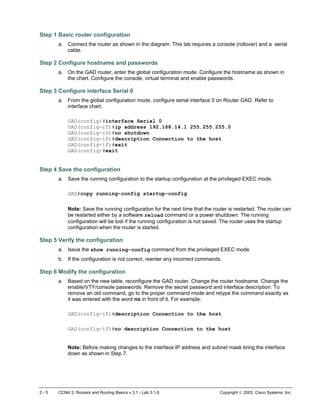
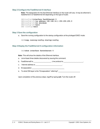
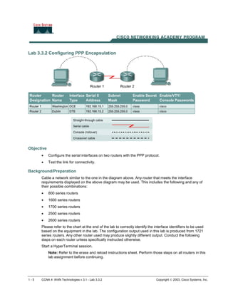
![Type ping and press Enter. Fill out the rest of the prompts as shown following:
Protocol [ip]:
Target IP address: 192.168.16.1
Repeat count [5]: 50
Datagram size [100]:
Timeout in seconds [2]:
Extended commands [n]:
Sweep range of sizes [n]:
Type escape sequence to abort.
Sending 50, 100-byte ICMP Echos to 192.168.16.1, timeout is 2 seconds:
!!!!!!!!!!!!!!!!!!!!!!!!!!!!!!!!!!!!!!!!!!!!!!!!!!
Success rate is 100 percent (50/50), round-trip min/avg/max = 32/32/40
ms
GAD#
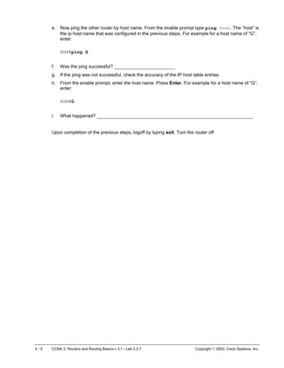
b. Notice how fast the ping response is. What was the average response time? _____________
Step 11 Perform another extended ping
a. Type ping and press Enter. Fill out the rest of the prompts as shown following.
During the ping, remove the crossover cable from the BHM FastEthernet port after 10 pings have
responded.
Protocol [ip]:
Target IP address: 192.168.16.1
Repeat count [5]: 50
Datagram size [100]: 1500
Timeout in seconds [2]:
Extended commands [n]:
Sweep range of sizes [n]:
Type escape sequence to abort.
Sending 50, 1500-byte ICMP Echos to 192.168.16.1, timeout is 2 seconds:
!!!!!!!!!!!!!!!U.U...........!!!!!!!!!!!!!!!!!!!!!
Success rate is 72 percent (36/50), round-trip min/avg/max =
432/434/464 ms
GAD#
b. What does the output from this extended ping say? _________________________________
c. Try doing this with a standard ping, can the cable be removed before the ping is over?
__________________________________________________________________________
d. What was the result of increasing the datagram size in the extended ping? _______________
Step 12 Perform an extended ping from the host
a. Exit the Telnet session and return to the host MS-DOS prompt. Type ping and press Enter.
b. Does the extended ping work the same way on the router as on the host? _______________
At the MS-dos prompt type:
C:>ping 192.168.16.1 –n 25
There should be 25 responses from the command.
c. Experiment with other combinations of the extended ping commands on both the router and the
host.
Upon completion of the previous steps, logoff by typing exit. Turn the router off.
4 - 6 CCNA 2: Routers and Routing Basics v 3.1 - Lab 4.2.5a Copyright 2003, Cisco Systems, Inc.](https://image.slidesharecdn.com/ciscolabs-practical2-150514105445-lva1-app6892/85/Cisco-labs-practical2-16-320.jpg)
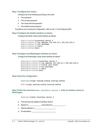
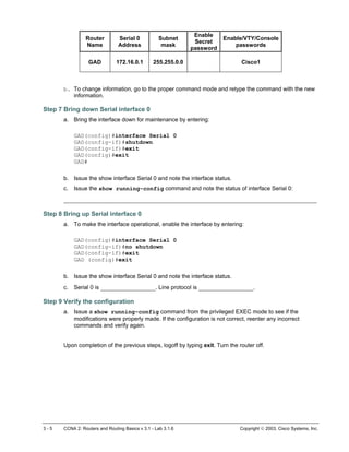
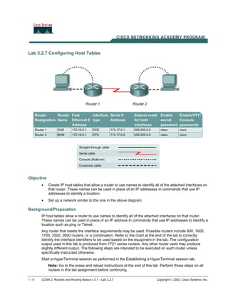
![4 - 5 CCNA 4: WAN Technologies v 3.1 - Lab 3.3.2 Copyright 2003, Cisco Systems, Inc.
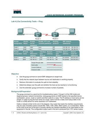
Erasing and reloading the router
Enter into the privileged EXEC mode by typing enable.
If prompted for a password, enter class (if that does not work, ask the instructor).
Router>enable
At the privileged EXEC mode, enter the command erase startup-config.
Router#erase startup-config
The responding line prompt will be:
Erasing the nvram filesystem will remove all files! Continue? [confirm]
Press Enter to confirm.
The response should be:
Erase of nvram: complete
Now at the privileged EXEC mode, enter the command reload.
Router(config)#reload
The responding line prompt will be:
System configuration has been modified. Save? [yes/no]:
Type n and then press Enter.
The responding line prompt will be:
Proceed with reload? [confirm]
Press Enter to confirm.
In the first line of the response will be:
Reload requested by console.
After the router has reloaded the line prompt will be:
Would you like to enter the initial configuration dialog? [yes/no]:
Type n and then press Enter.
The responding line prompt will be:
Press RETURN to get started!
Press Enter.
Now the router is ready for the assigned lab to be performed.](https://image.slidesharecdn.com/ciscolabs-practical2-150514105445-lva1-app6892/85/Cisco-labs-practical2-20-320.jpg)

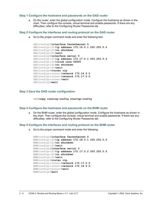
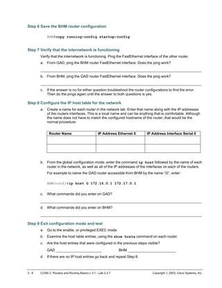
This document provides instructions for configuring IP host tables on two routers, GAD and BHM, to allow them to use names to identify their interfaces. The key steps are: 1. Configure the hostname, passwords, interfaces and RIP routing on router GAD with IP addresses 172.16.0.1, 172.17.0.1. 2. Configure the hostname, passwords, interfaces and RIP routing on router BHM with IP addresses 172.18.0.1, 172.17.0.2. 3. Save the configurations on both routers. 4. Create IP host tables on each router to allow using names instead of IP addresses to identify interfaces in