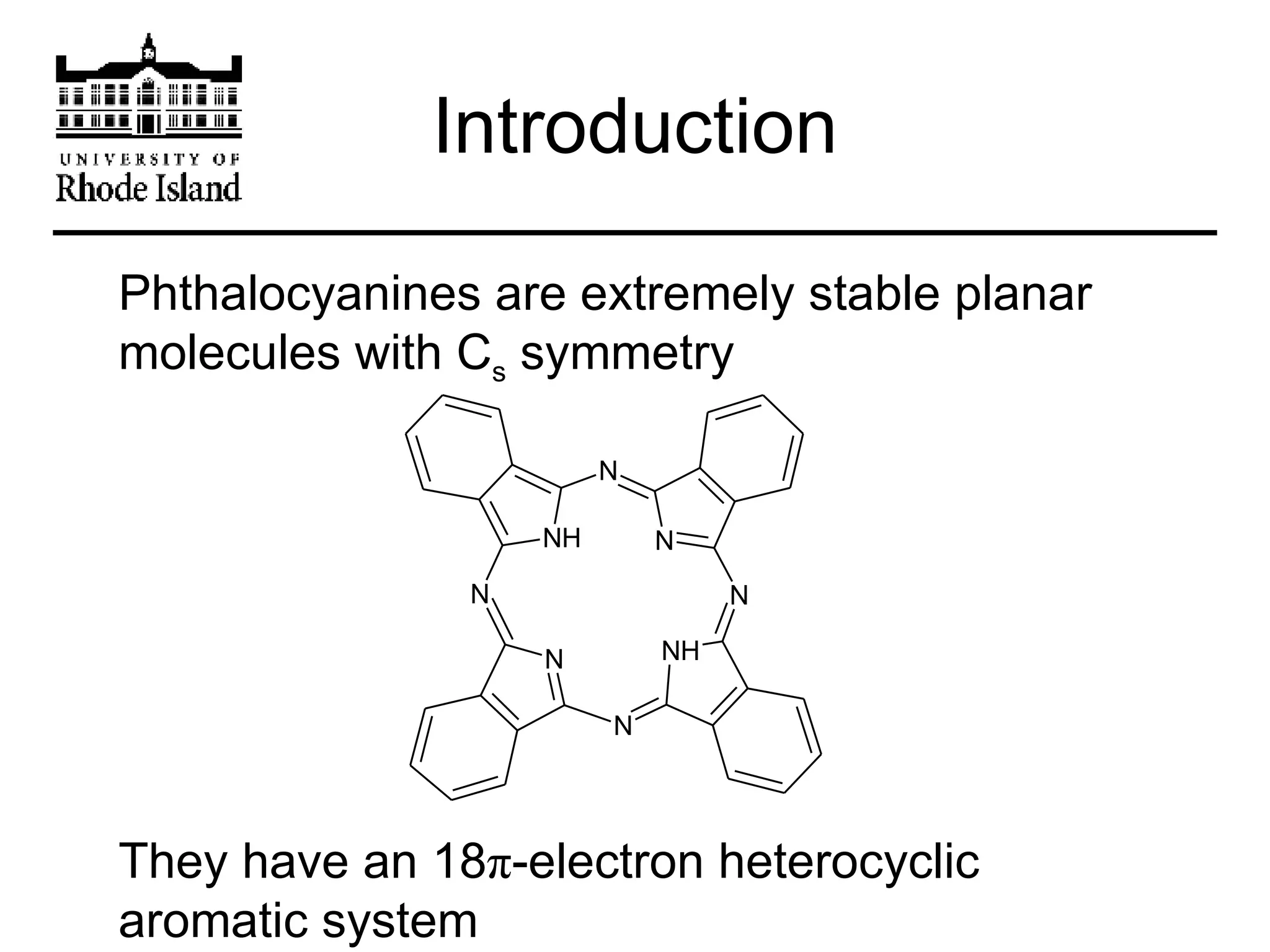
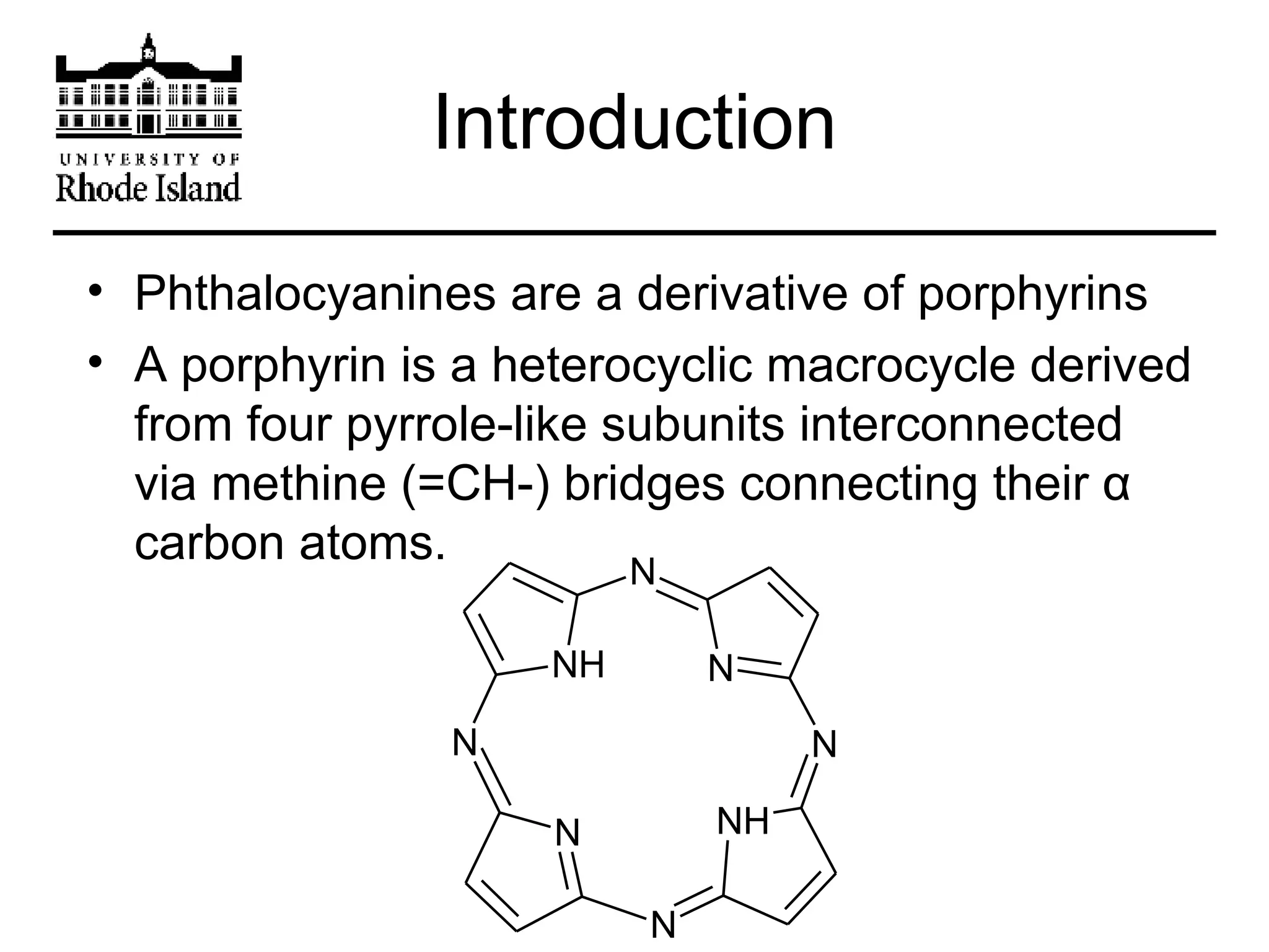
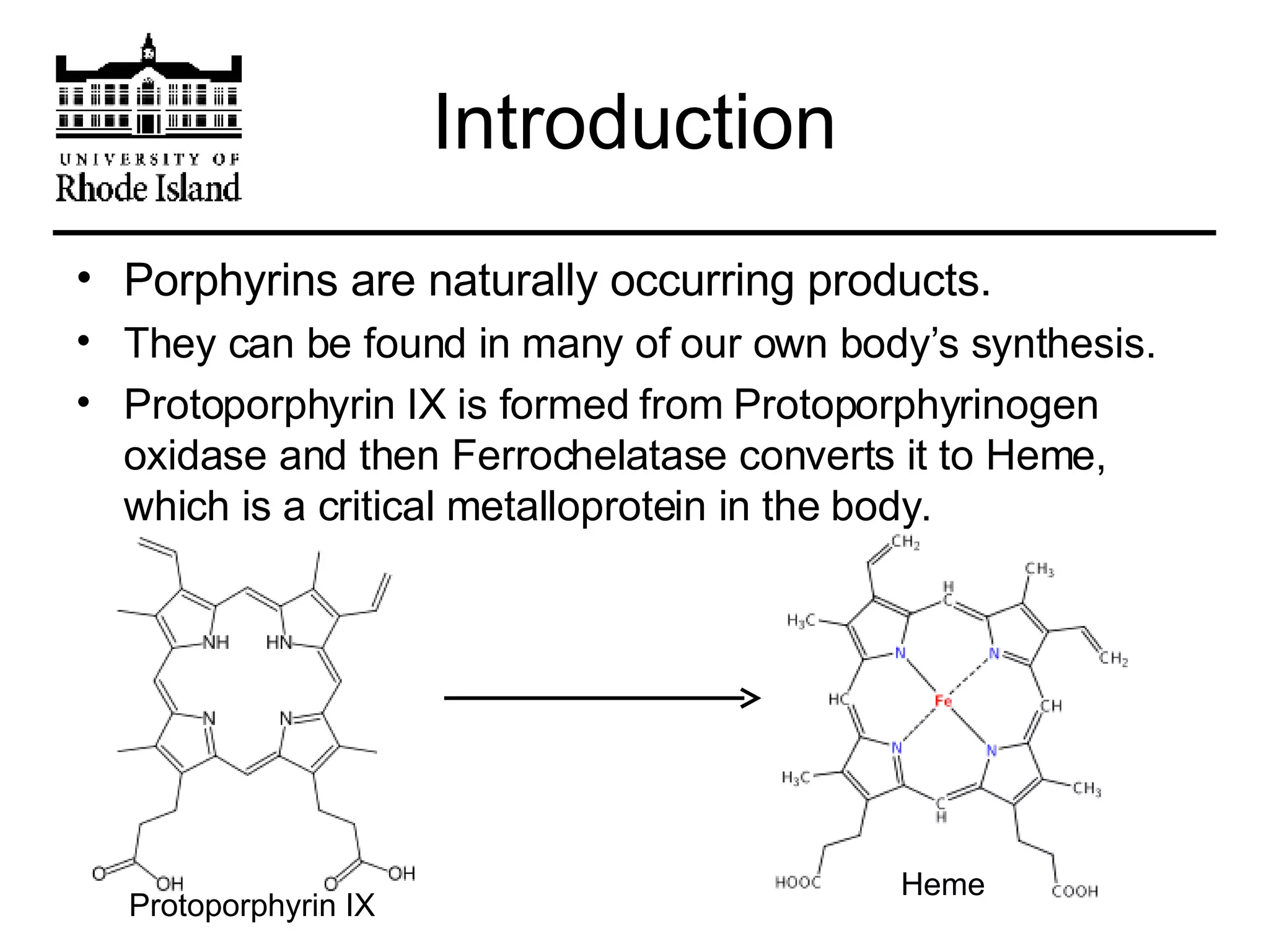
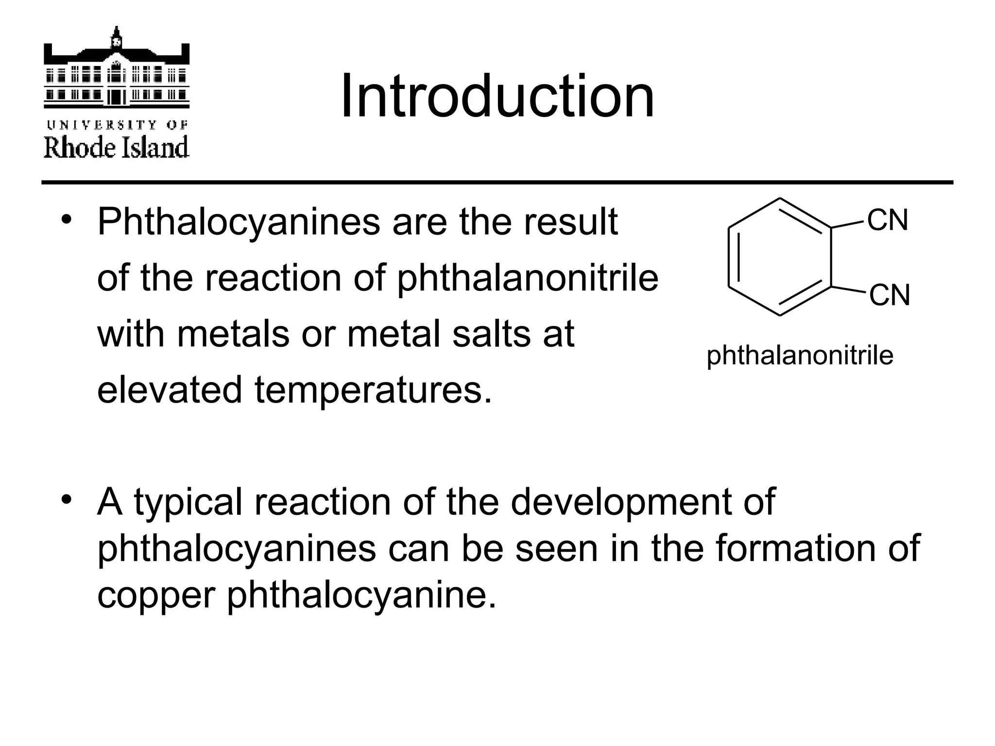
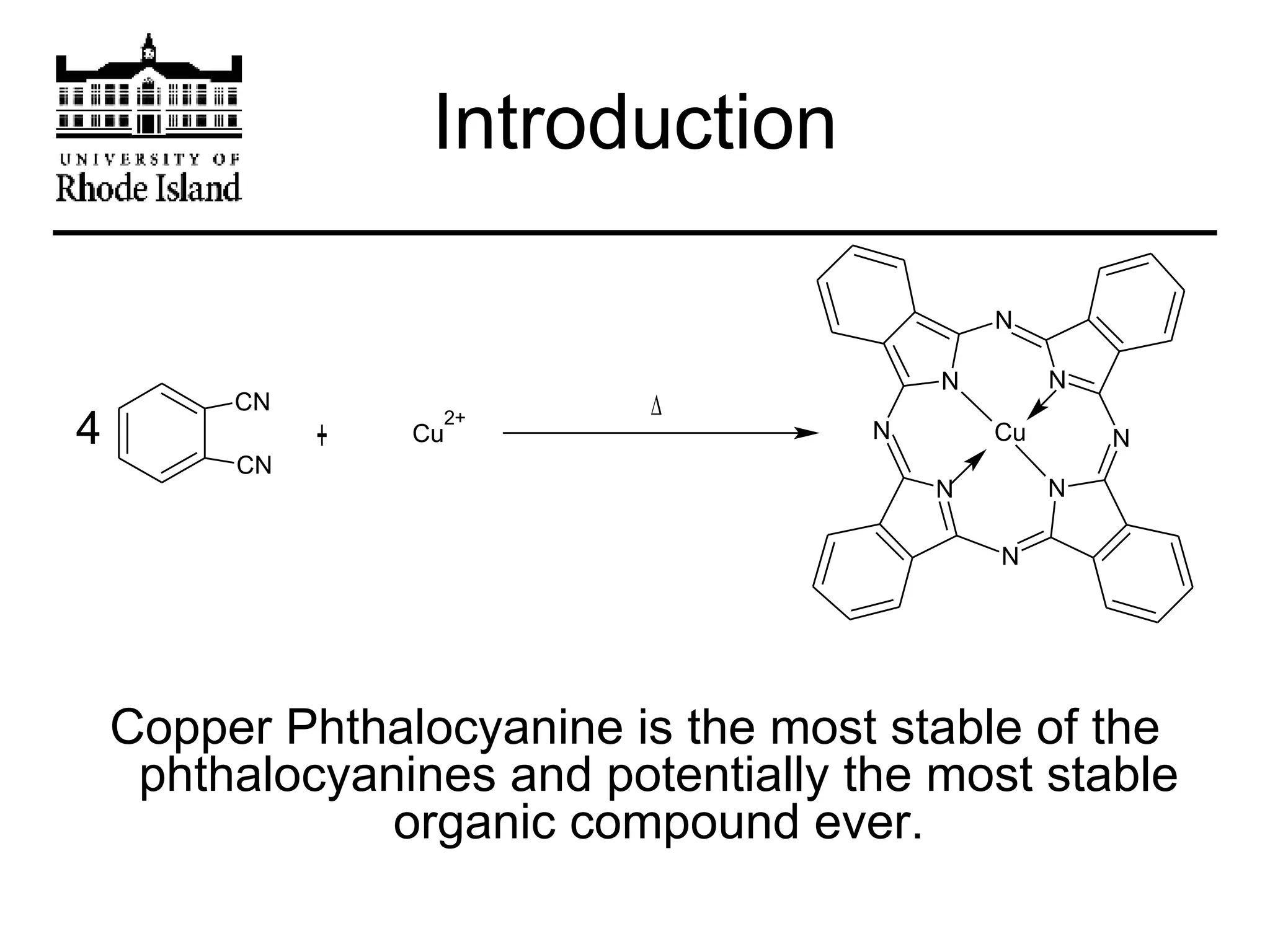
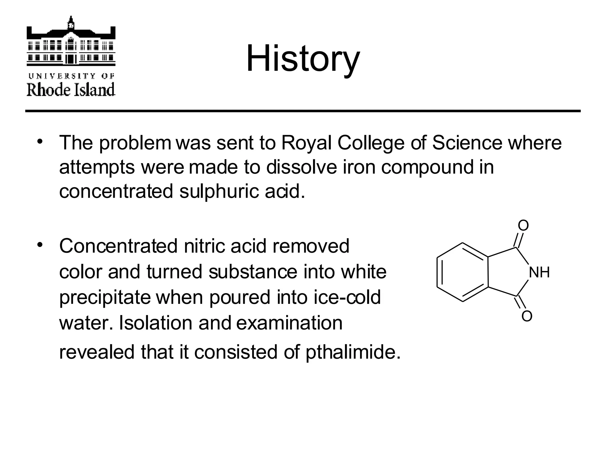
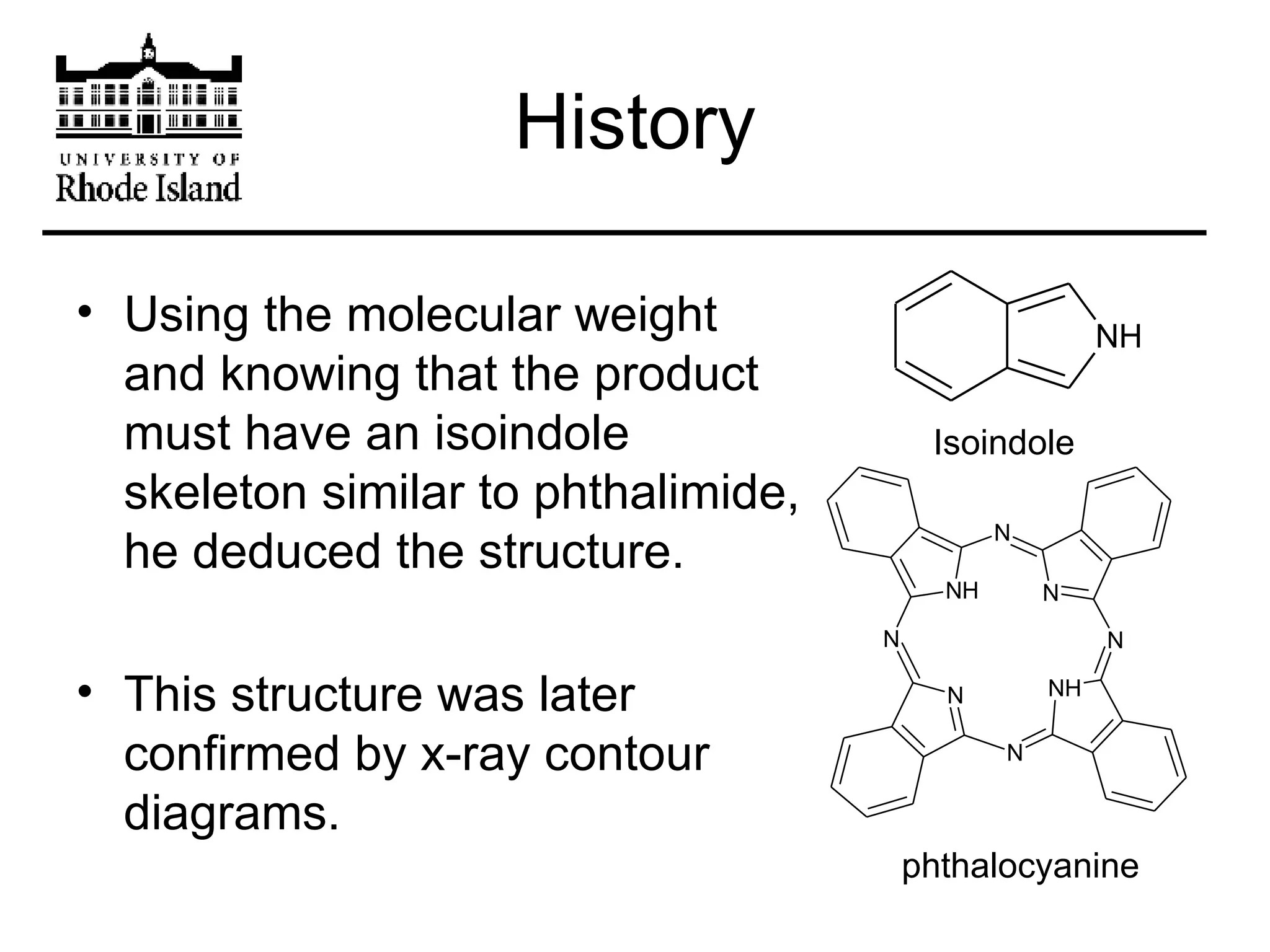
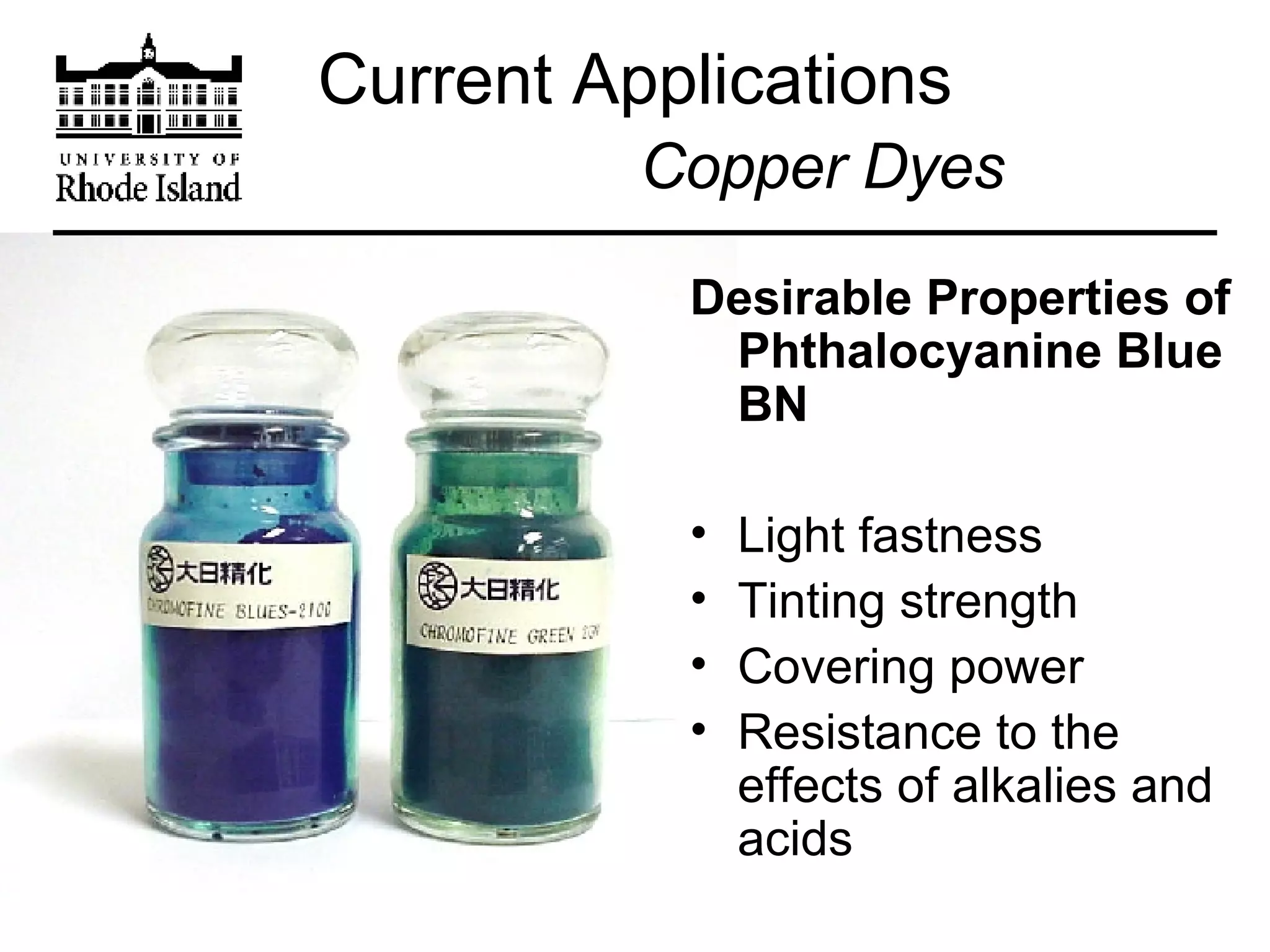
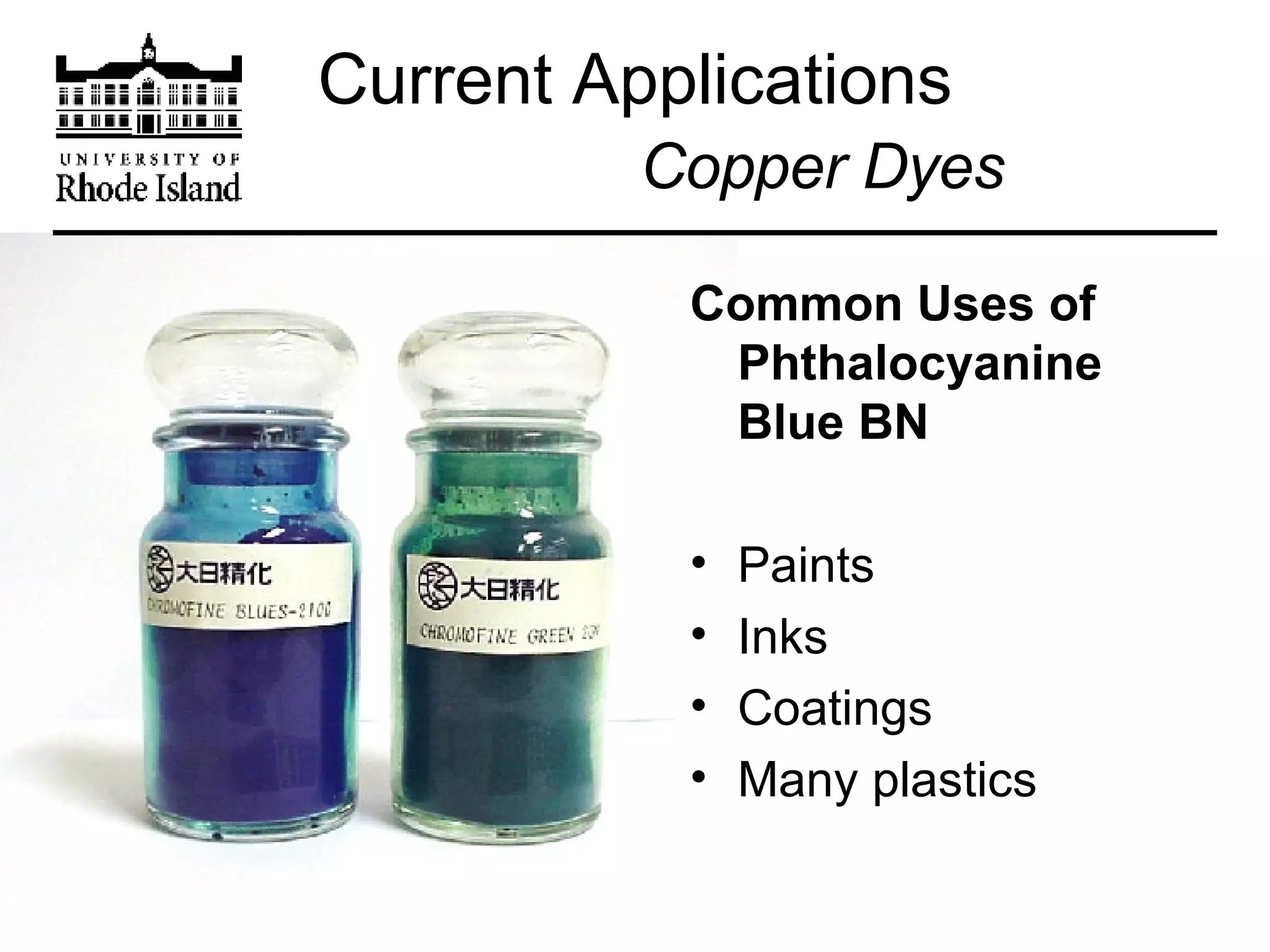
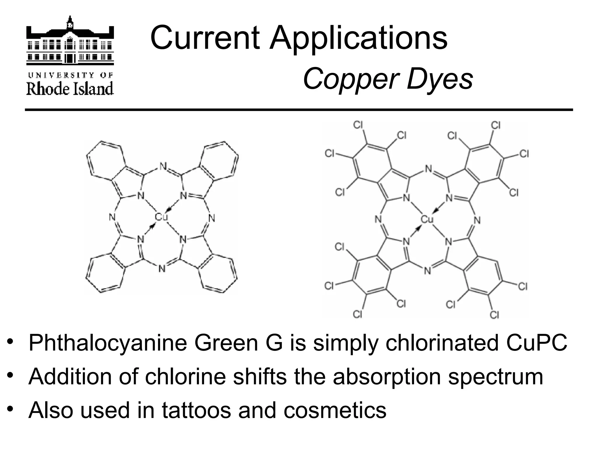
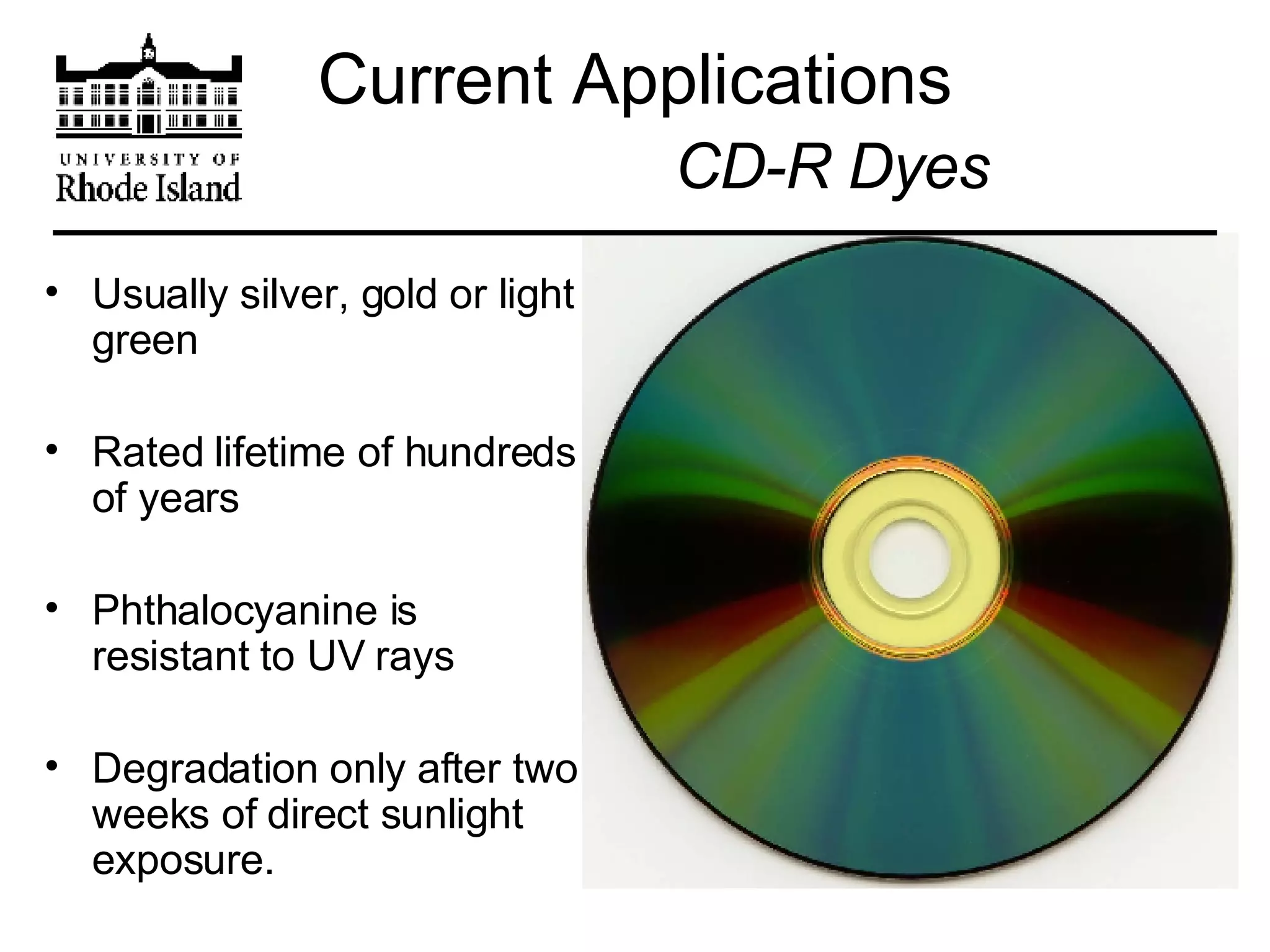
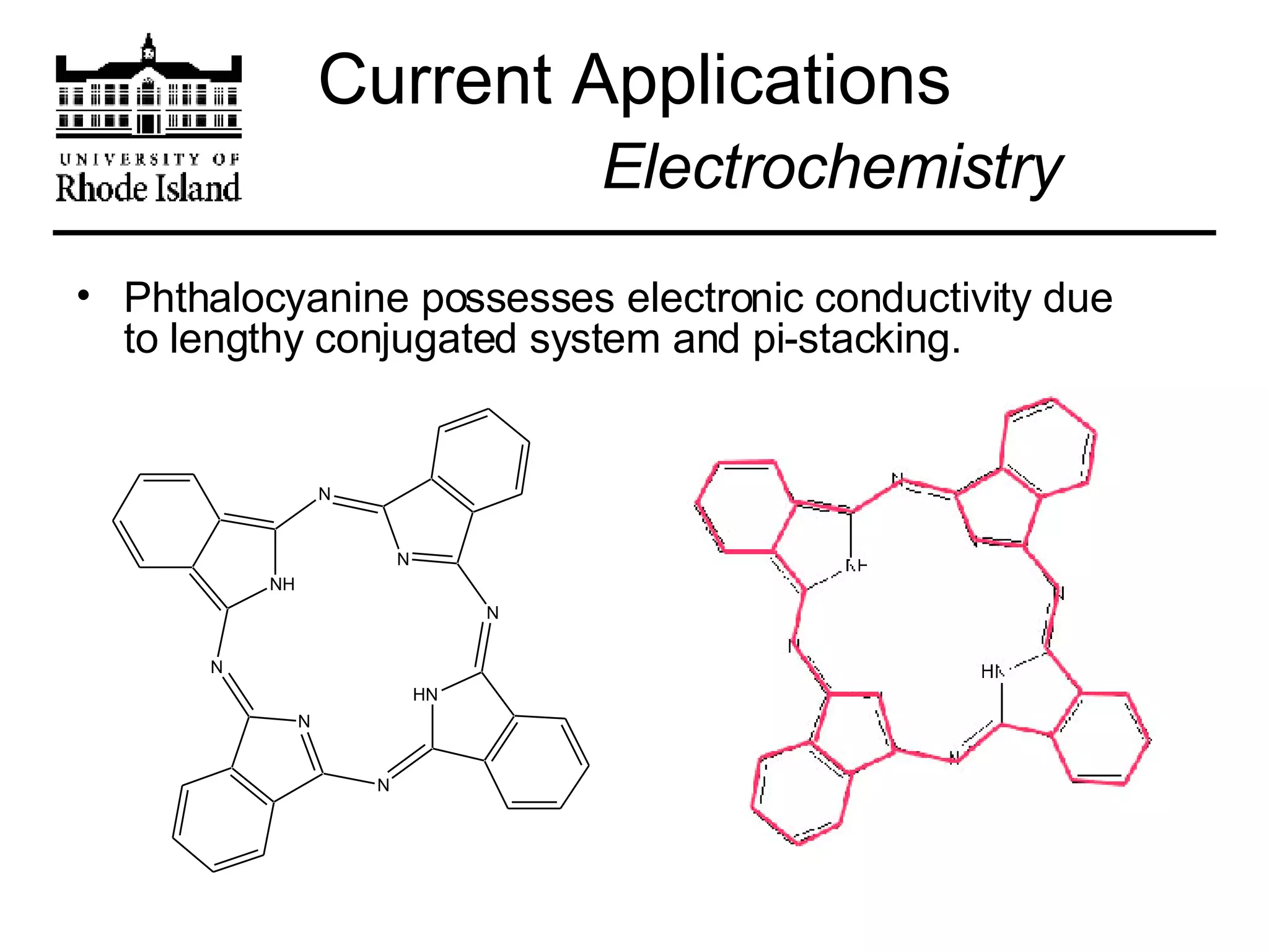
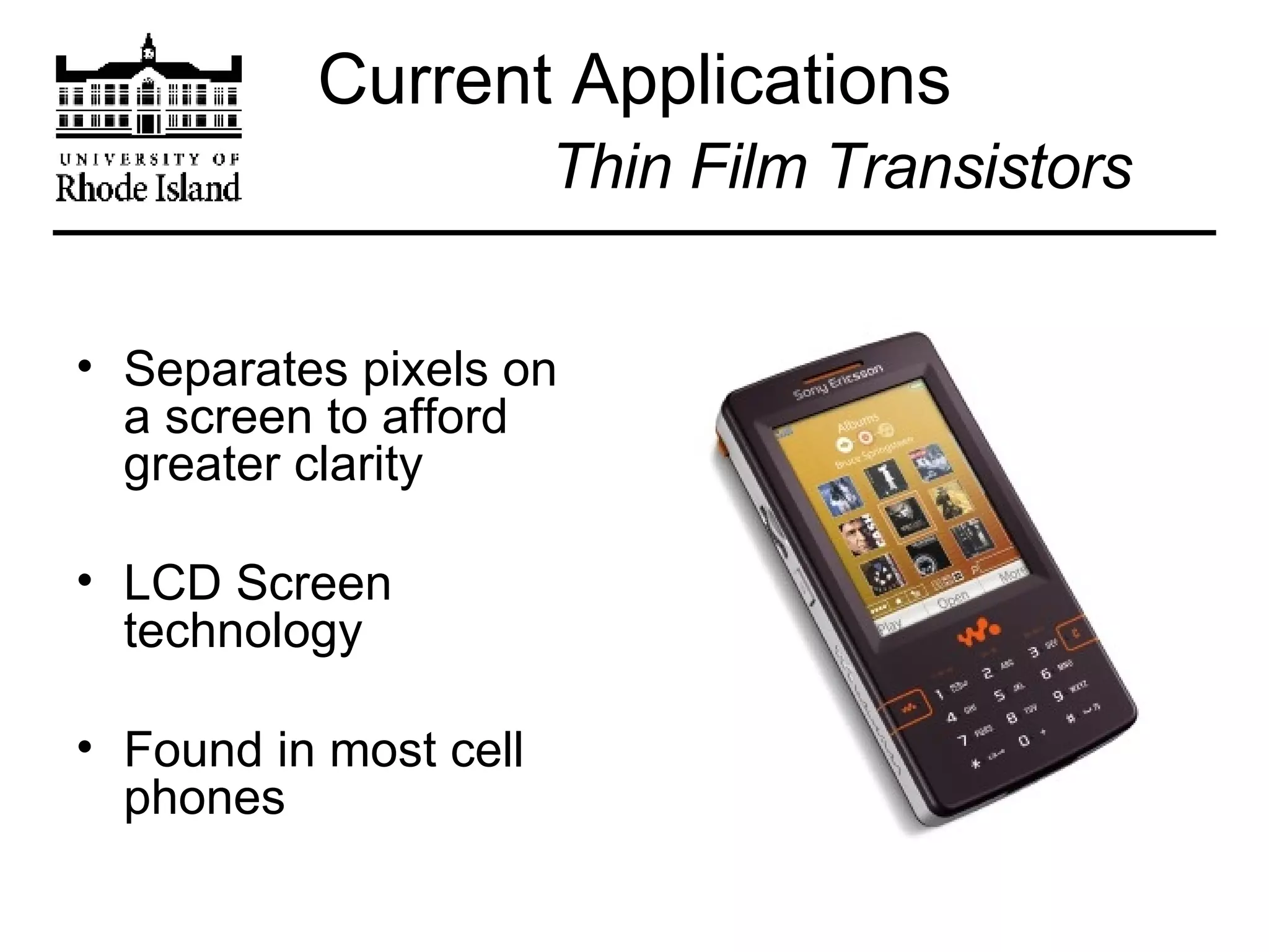
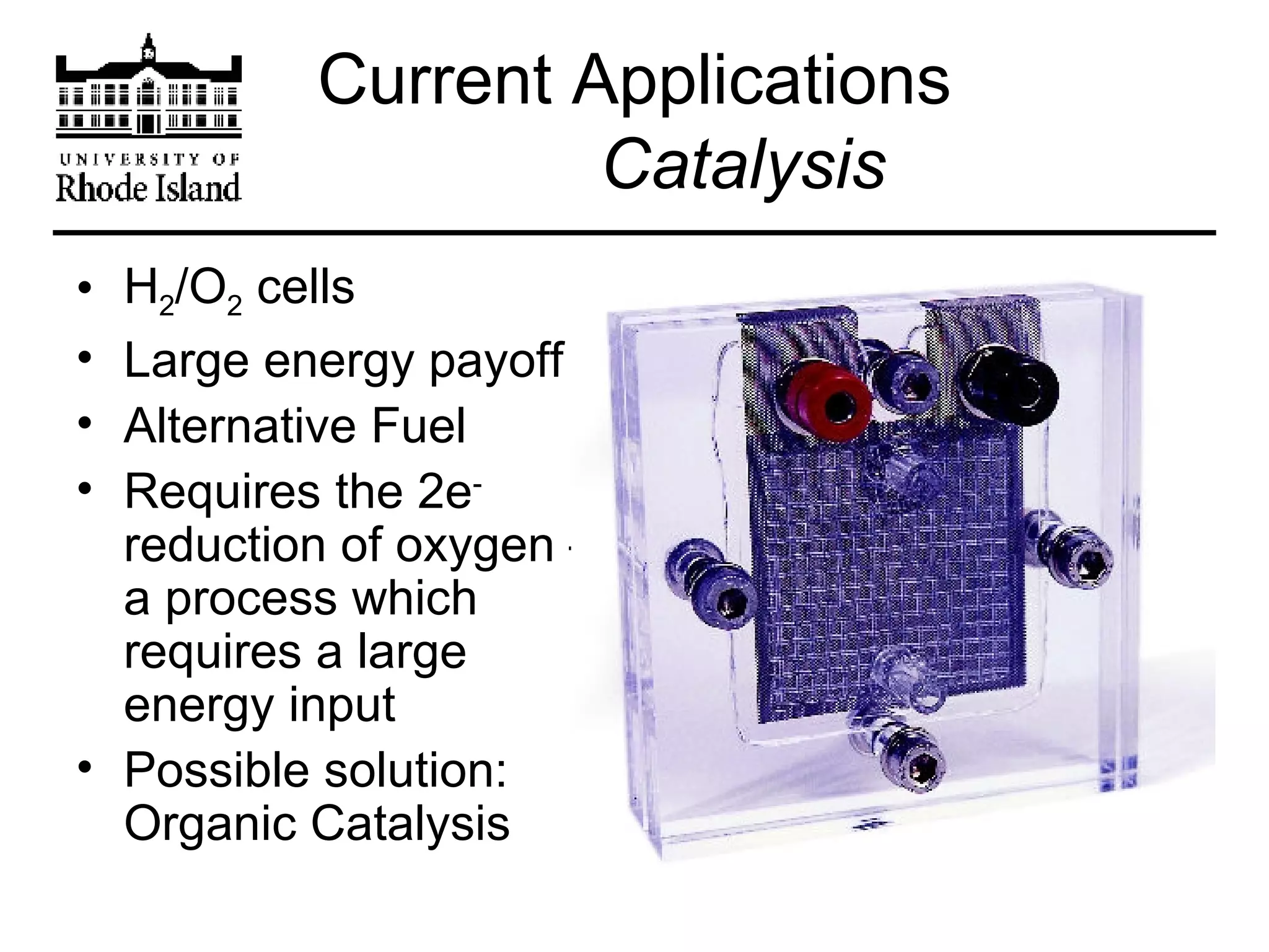
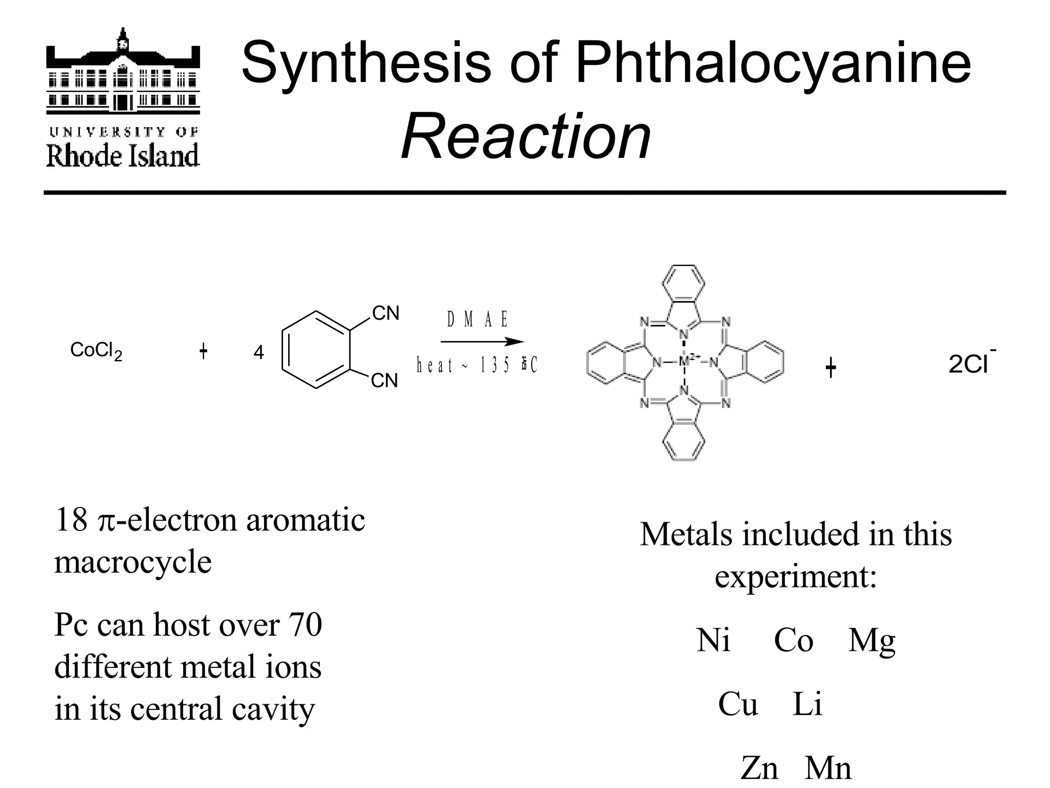
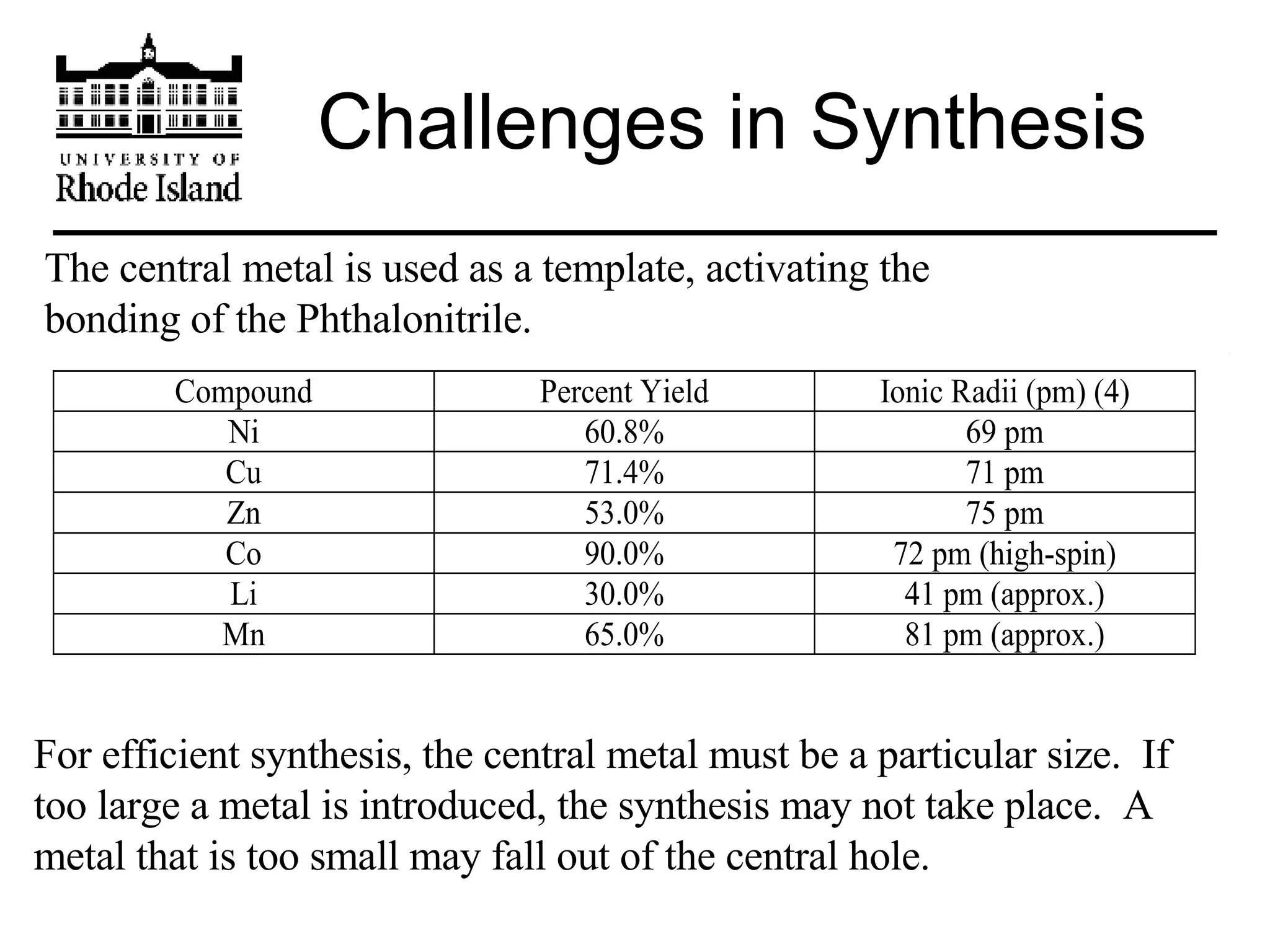
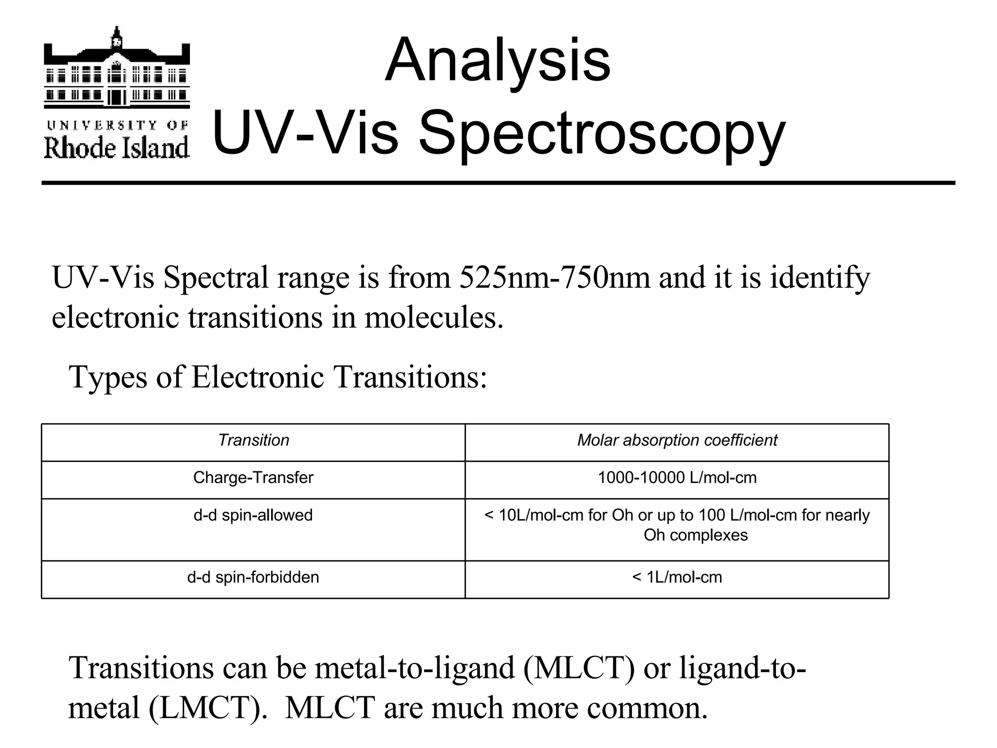
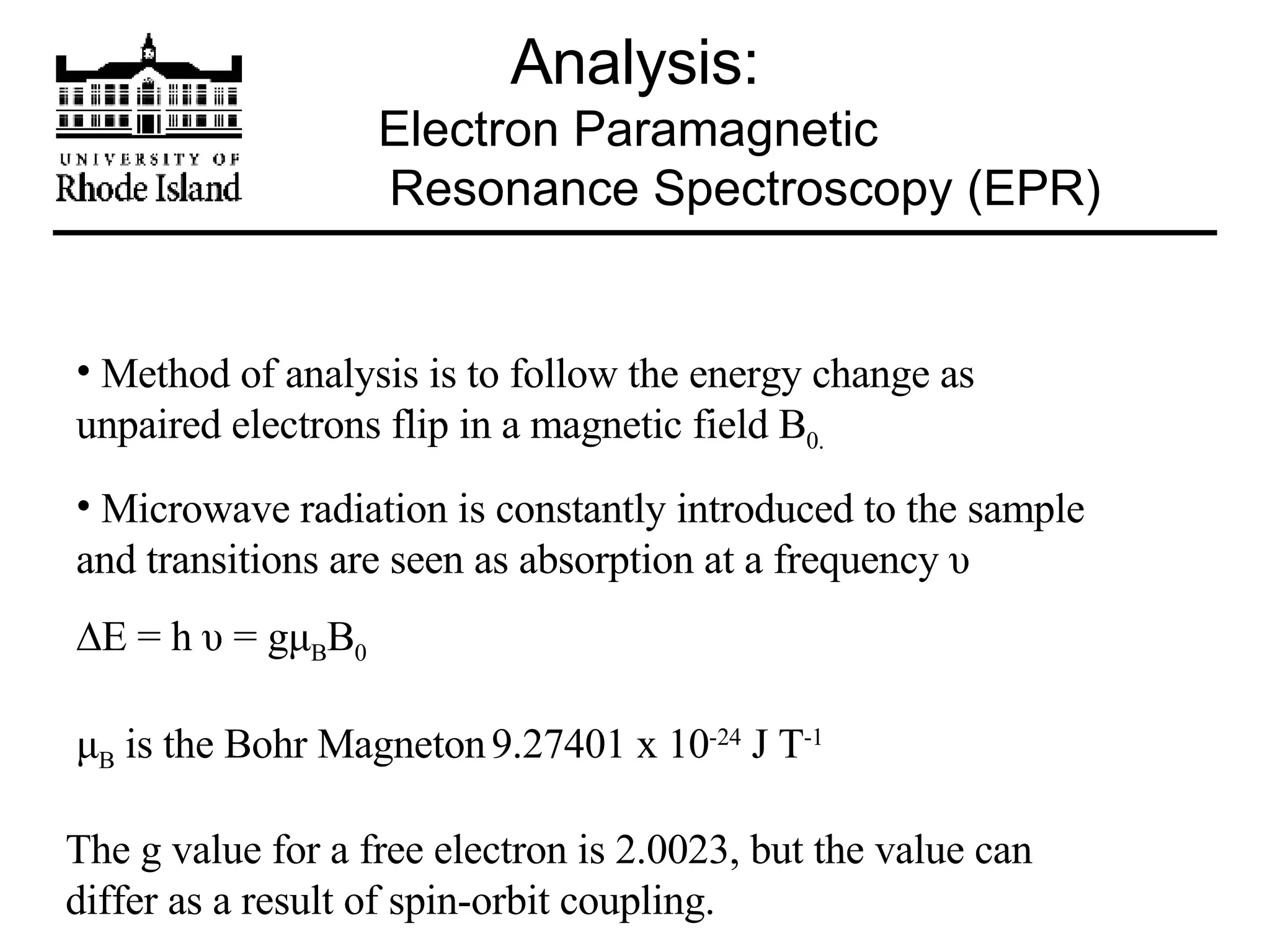
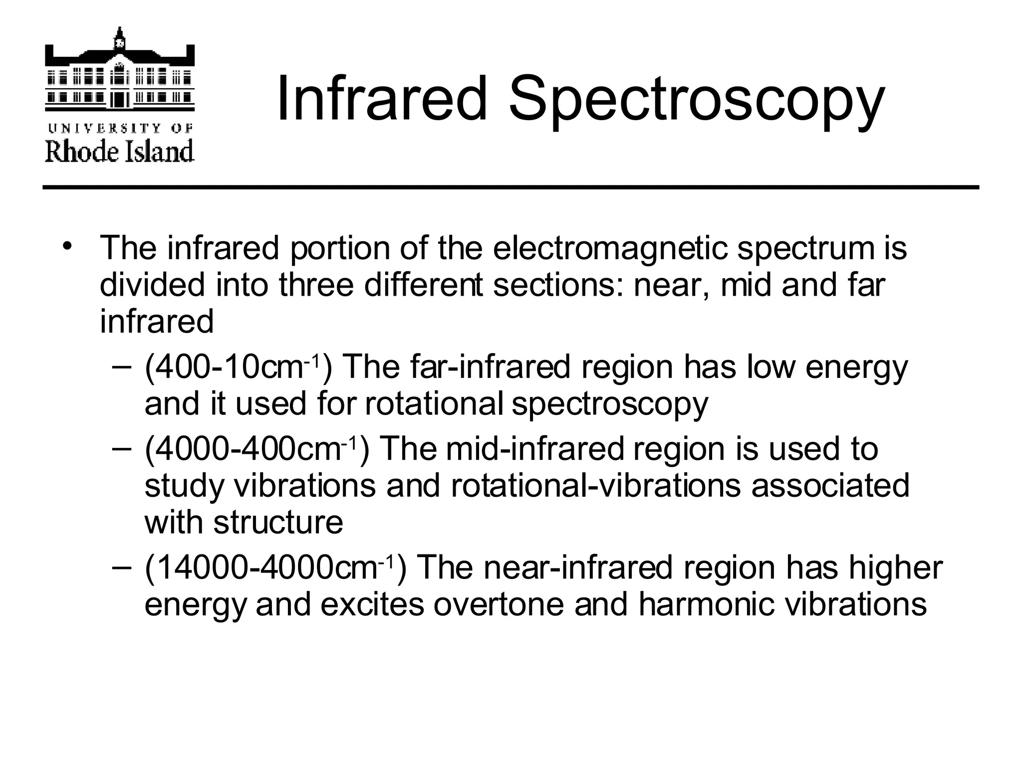
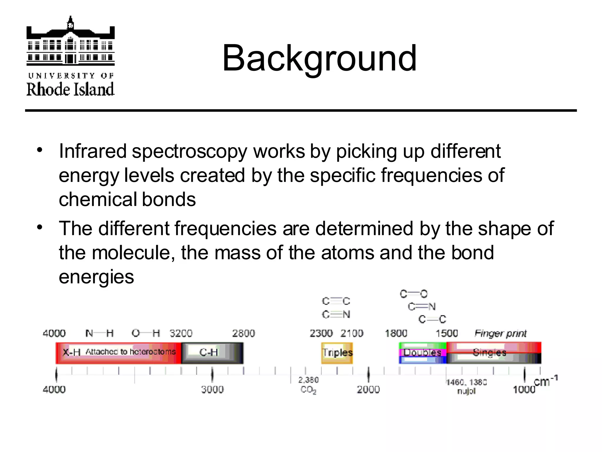
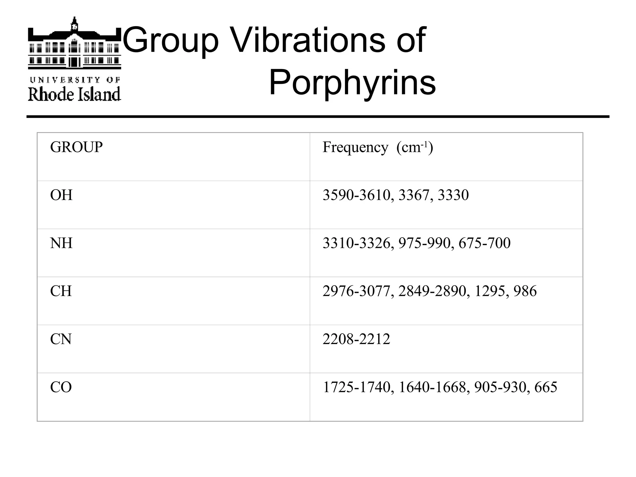
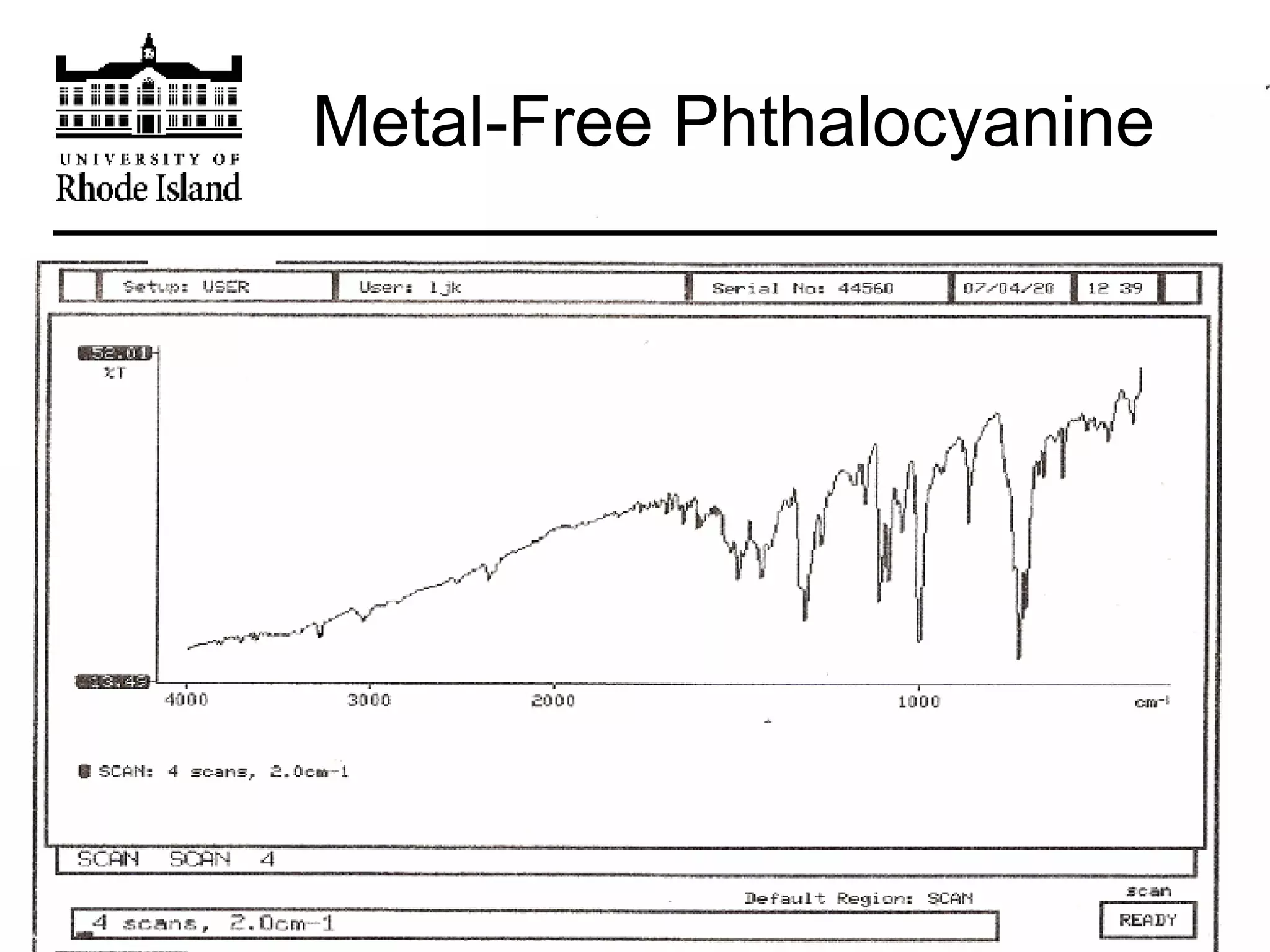
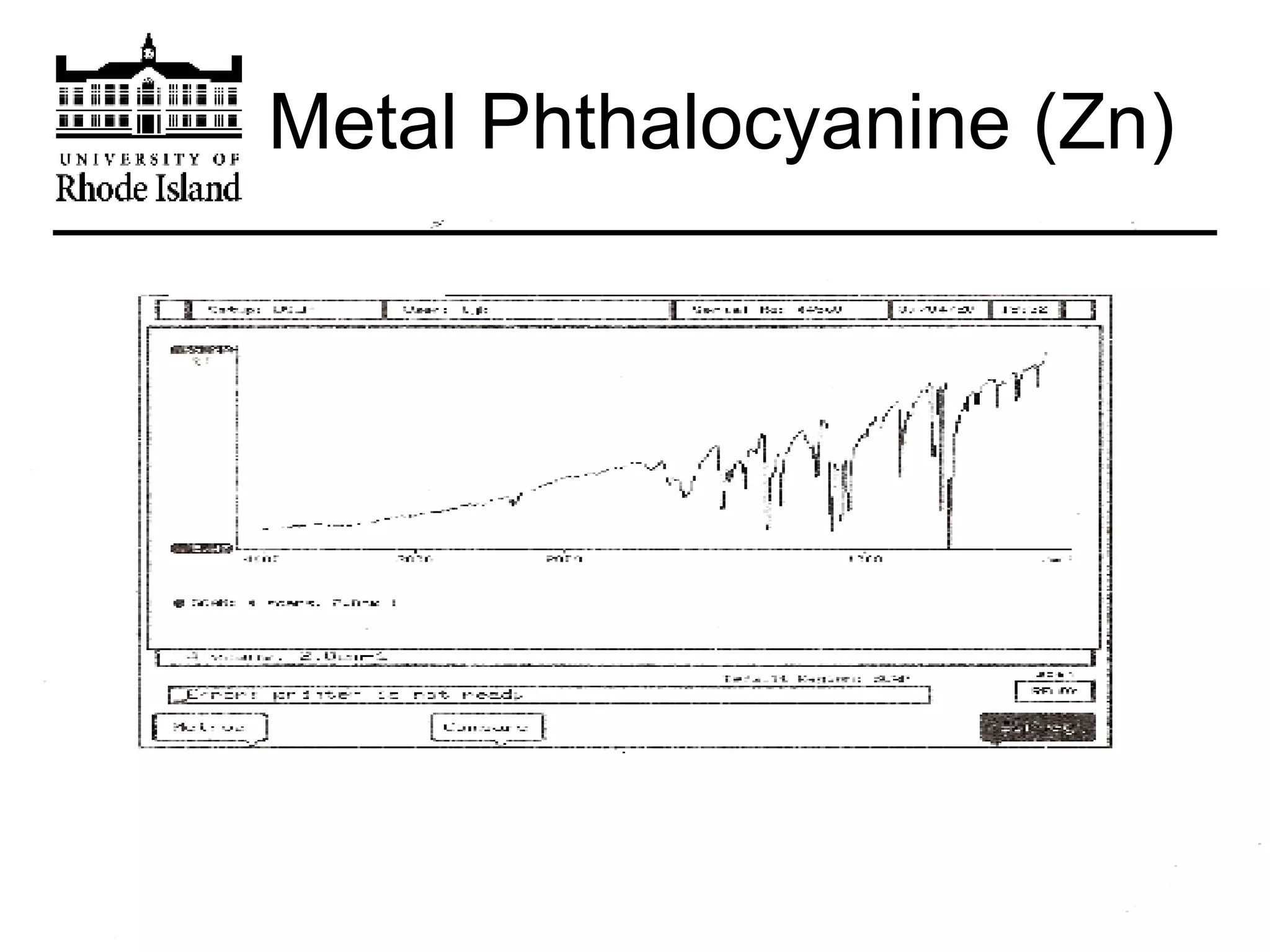
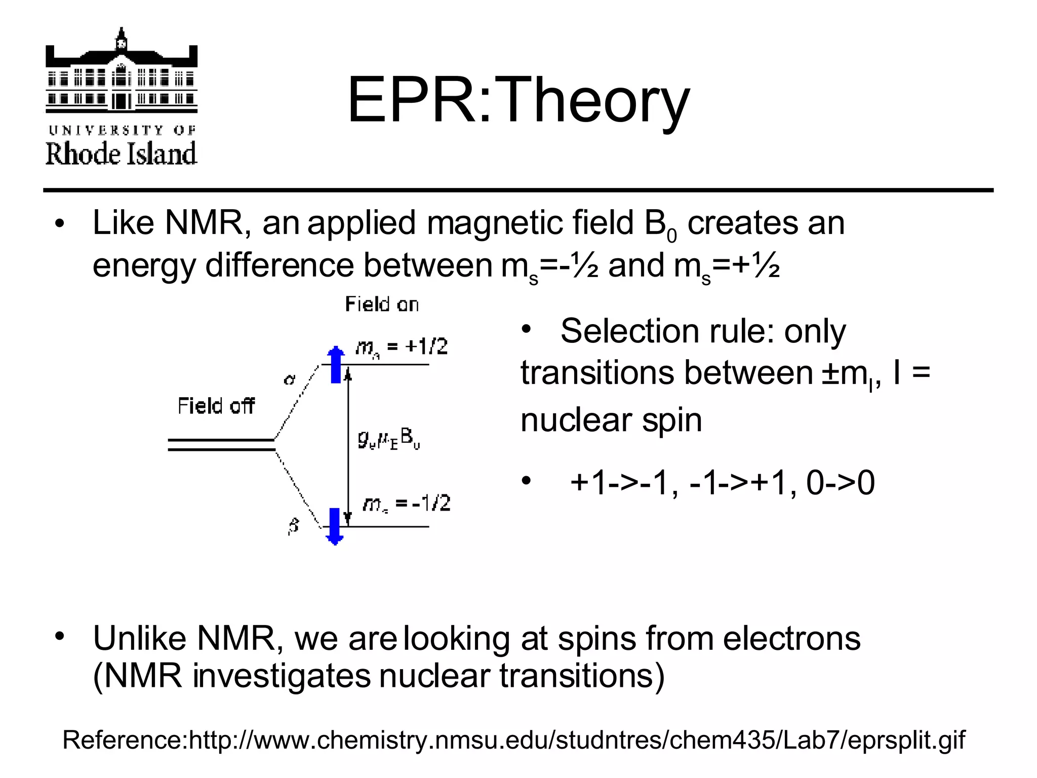
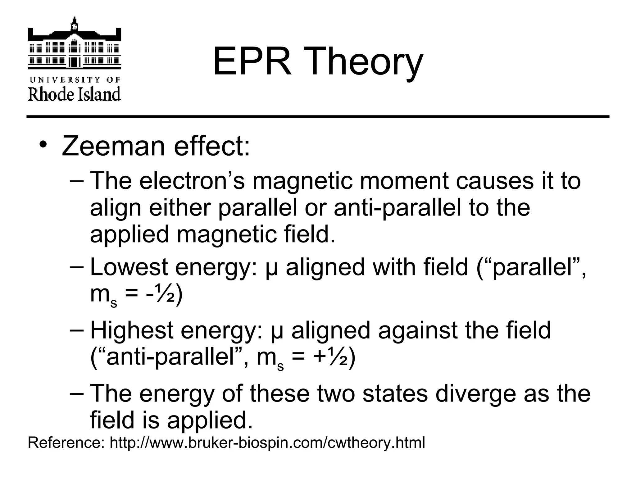
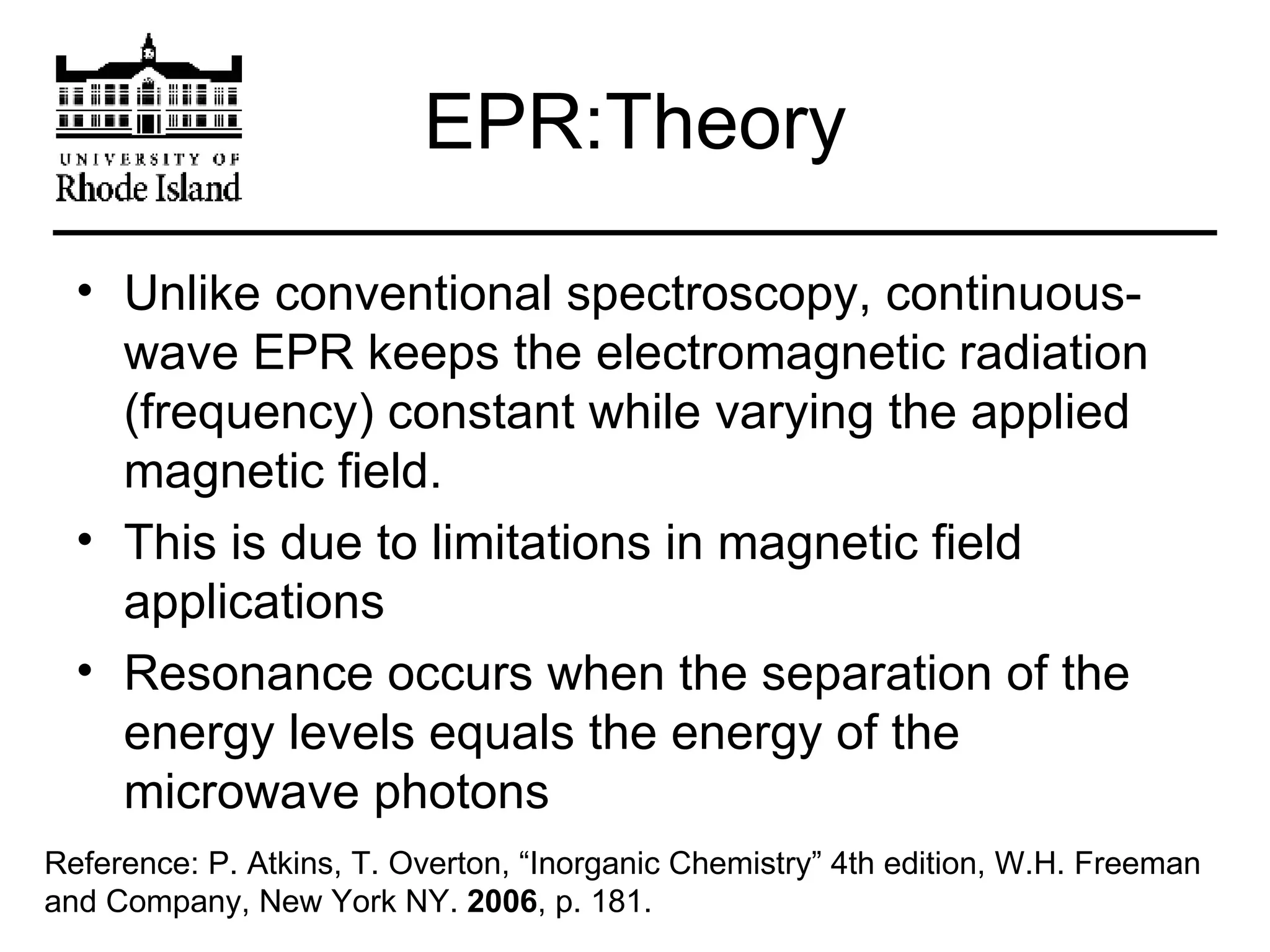
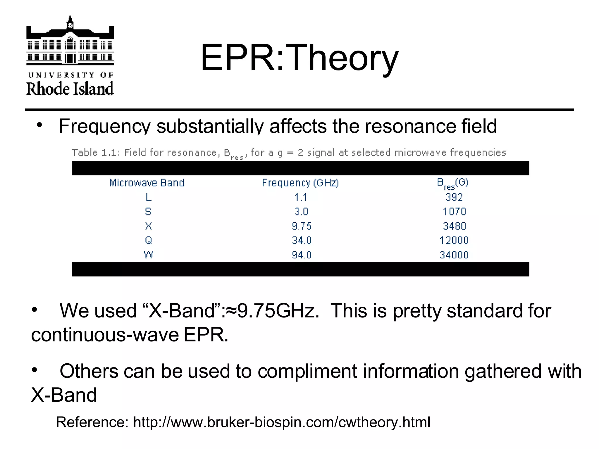
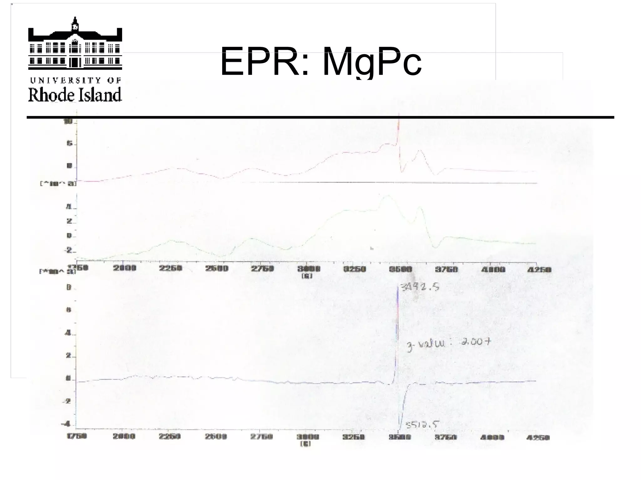
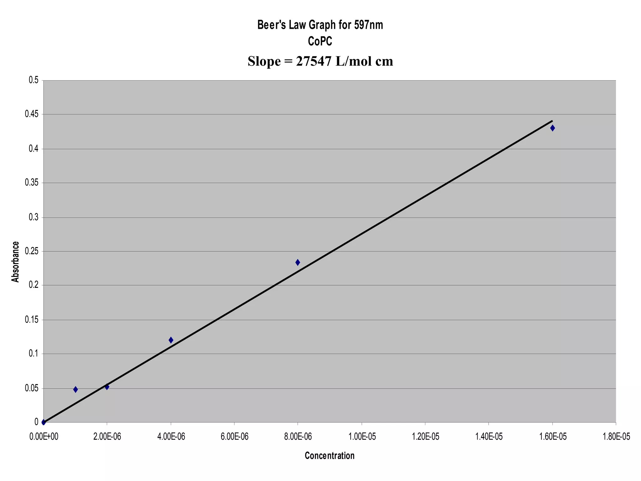
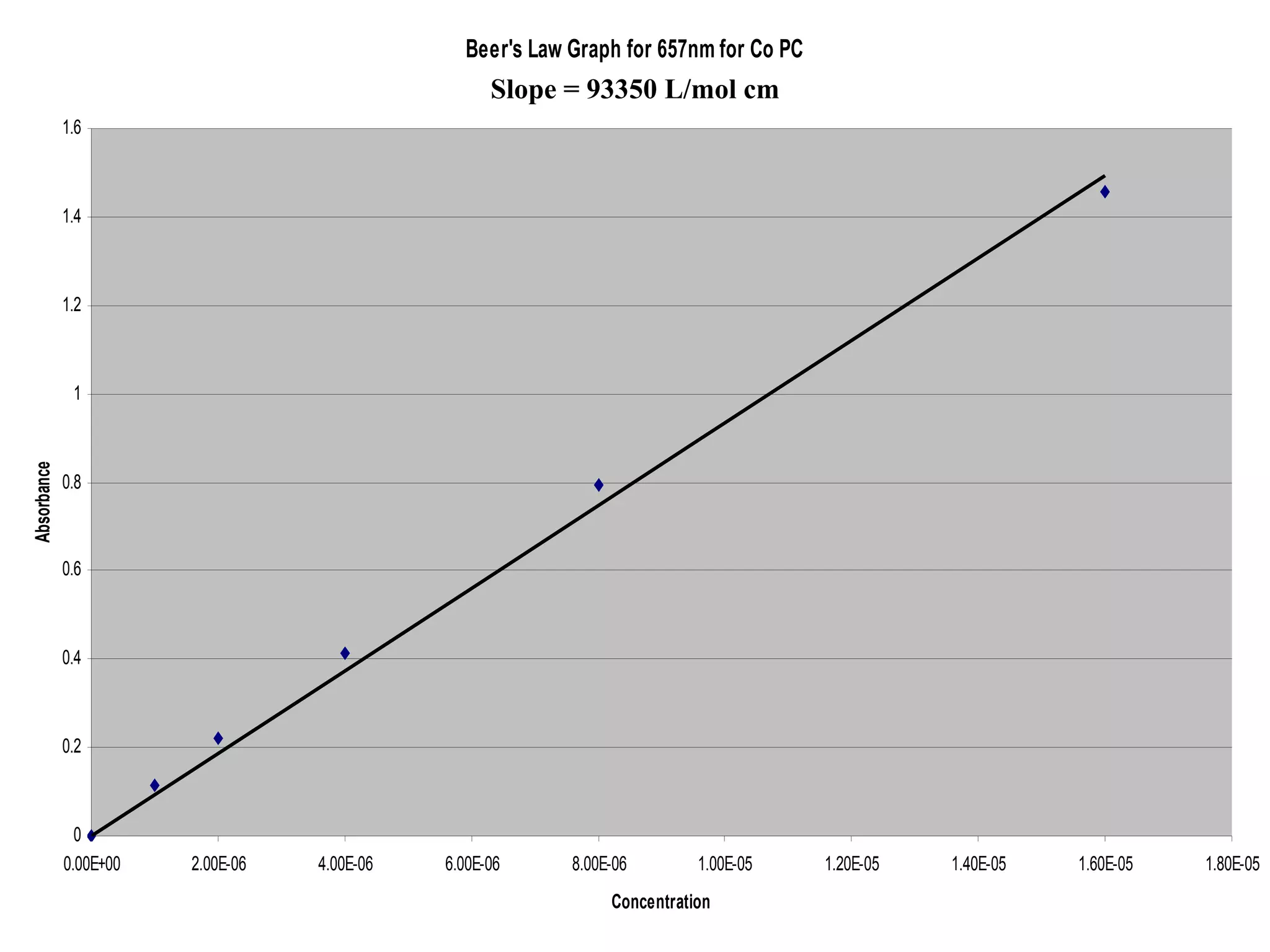
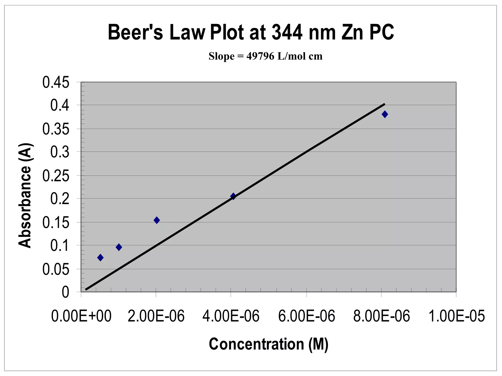
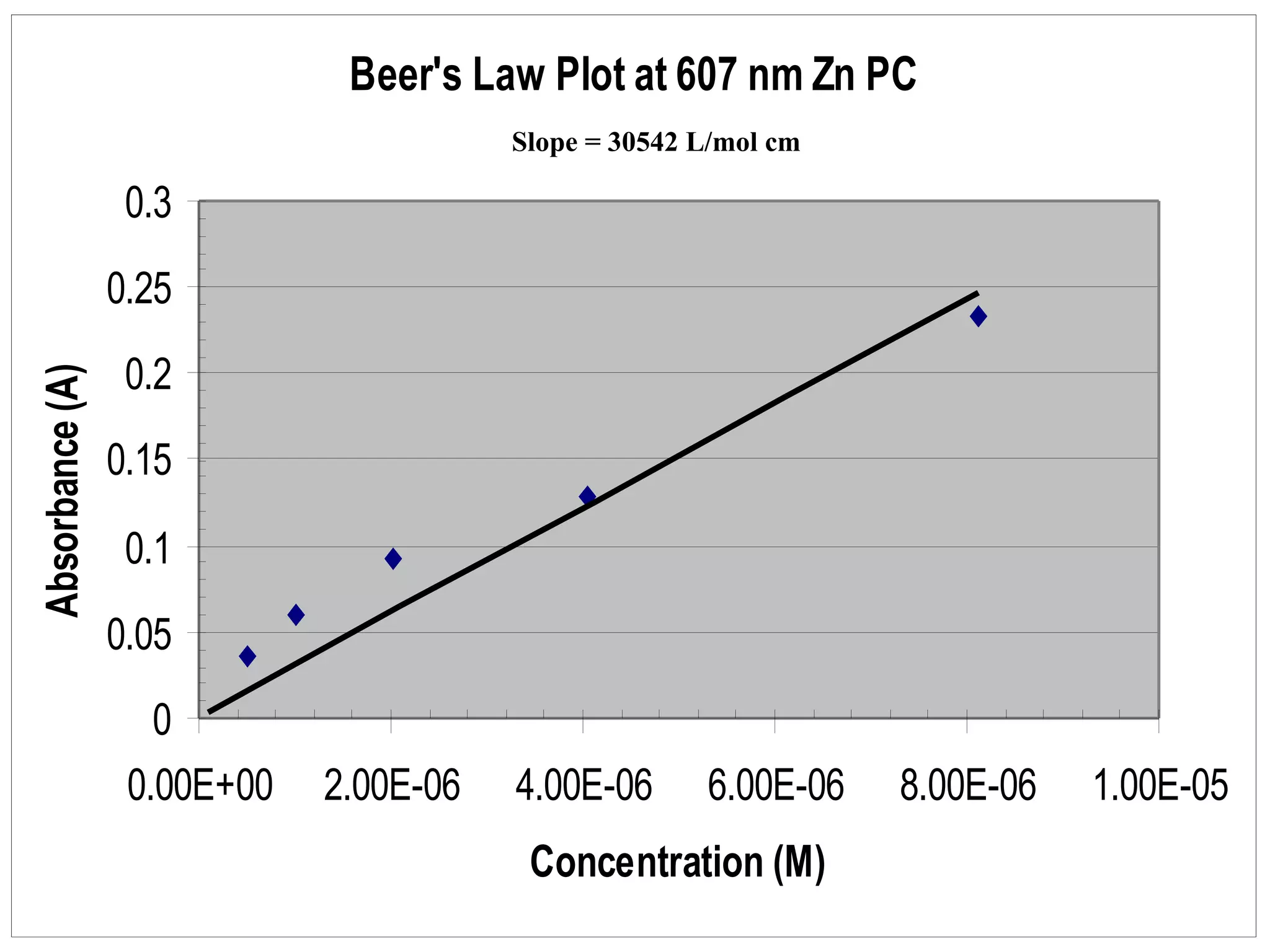
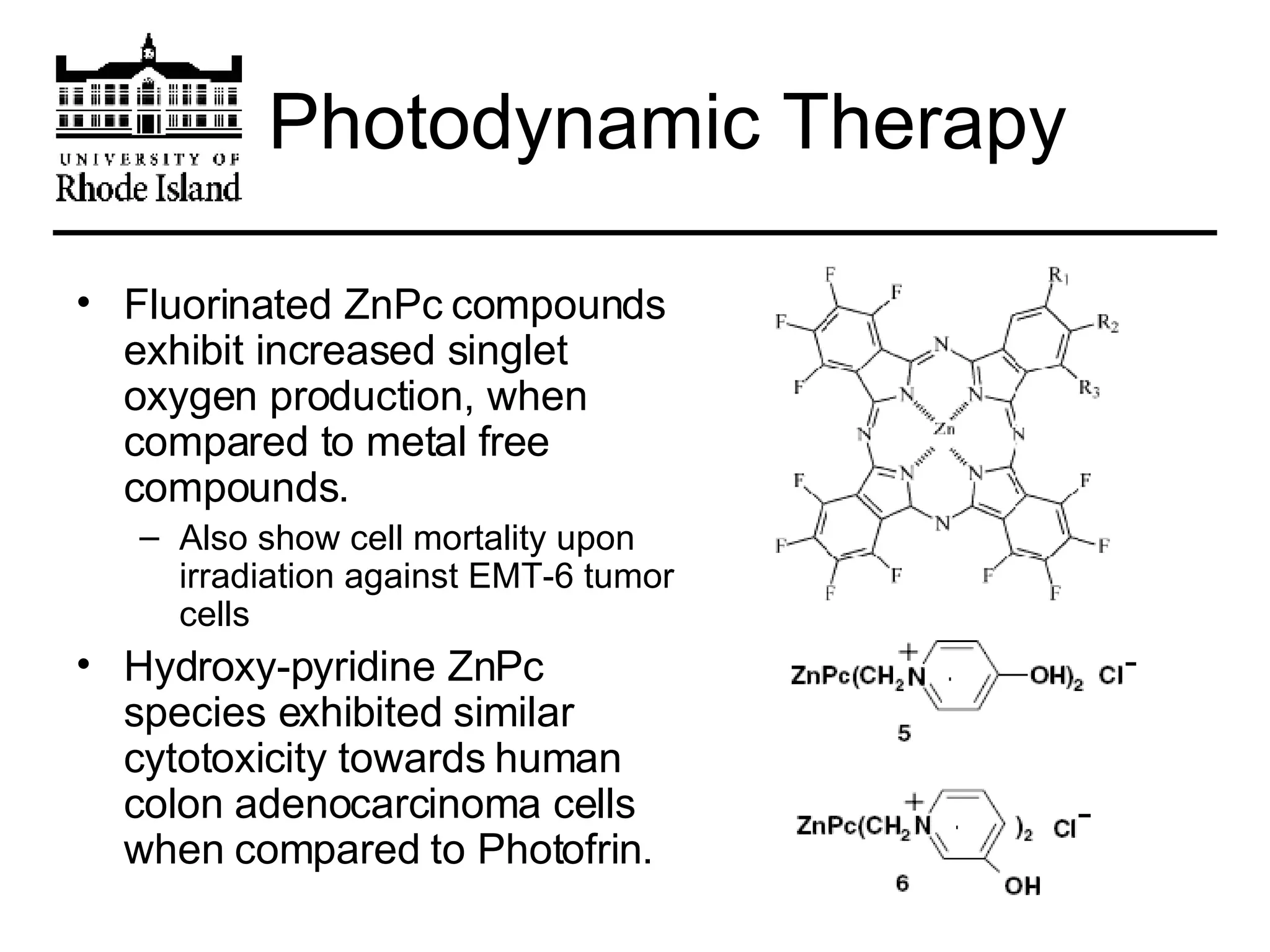
A Comprehensive Investigation of Phthalocyanine Metal Cation Complexes   J. Canino, J. Head, J. Kasparian,  G. Lincourt, A. Mc Cusker, A. Mills, J. Prata  University of Rhode Island CHM402 Spring 2007
Outline Introduction and History Current Applications Synthesis and Analysis Overview IR Analysis EPR Analysis UV-Vis Analysis Conclusion and Future Applications Acknowledgements
Phthalocyanines are extremely stable planar molecules with C s  symmetry They have an 18 π -electron heterocyclic aromatic system Introduction
Introduction Phthalocyanines are a derivative of porphyrins A porphyrin is a heterocyclic macrocycle derived from four pyrrole-like subunits interconnected via methine (=CH-) bridges connecting their α carbon atoms.
Introduction Porphyrins are naturally occurring products. They can be found in many of our own body’s synthesis. Protoporphyrin IX is formed from Protoporphyrinogen oxidase and then Ferrochelatase converts it to Heme, which is a critical metalloprotein in the body. Protoporphyrin IX Heme
Introduction Phthalocyanines are the result  of the reaction of phthalanonitrile  with metals or metal salts at  elevated temperatures.  A typical reaction of the development of phthalocyanines can be seen in the formation of copper phthalocyanine. phthalanonitrile
Introduction Copper Phthalocyanine is the most stable of the phthalocyanines and potentially the most stable organic compound ever. 4
History The word phthalocyanine is derived from the Greek words for naphtha, meaning rock oil and cyanine, meaning blue This term was first used by Sir Patrick Linstead in 1933 to describe a new class of organic compounds. Phthalocyanine itself, however, is believed to have been discovered in 1907 as an accidental by-product of the synthesis of o-cyanobenzamide
History The development of phthalocyanine started in 1928 at Scotland Dyes Works The workers using phthalimide found it to be contaminated with a dark colored impurity They called in their scientists to isolate the product and determine its nature.
History They collected samples of the impurity but it was still mixed with the phthalimide. They found that treating the impurity with boiling water separated the two compounds. Phthalimide dissolved in the water but the impurity remained in its solid form. Simple filtration separated the two.
History With further investigation it was found that the impurity was extremely resistant to both heat and most reagents. Phthalimide was made from phthalic anhydride and ammonia in a large enamel coated iron drum They found some small chips in the enamel of the drum leading them to believe that some iron had gotten into the phthalimide and created the impurity.
History They determined that Iron was the source of the dark color and they set out to remove the iron. They tried boiling it with hydrochloric acid and testing for it in filtered liquid and testing it with ammonium thiocyanate. Iron was not removable by these means.
History The problem was sent to Royal College of Science where attempts were made to dissolve iron compound in concentrated sulphuric acid.  Concentrated nitric acid removed  color and turned substance into white  precipitate when poured into ice-cold water. Isolation and examination  revealed that it consisted of pthalimide.
History When cuprous chloride was added to molten phthalimide, there was a vigorous reaction with the formulation of a colored product. They determined that the metals had to be a key part of the structure of this new compound. With this new element in the mix, J. Monteath Robertson at the Royal College of Science set out to discover the structure of the molecule.
History First he determined the empirical formula using micro-combustion techniques. Once he had the empirical formula the molecular weight was also determined.
History Using the molecular weight and knowing that the product must have an isoindole skeleton similar to phthalimide, he deduced the structure. This structure was later confirmed by x-ray contour diagrams. Isoindole phthalocyanine
Current Applications   Copper Dyes Desirable Properties of Phthalocyanine Blue BN Light fastness Tinting strength Covering power Resistance to the effects of alkalies and acids
Current Applications   Copper Dyes Common Uses of Phthalocyanine  Blue BN Paints Inks  Coatings Many plastics
Current Applications   Copper Dyes Phthalocyanine Green G is simply chlorinated CuPC Addition of chlorine shifts the absorption spectrum Also used in tattoos and cosmetics
Current Applications   CD-R Dyes Usually silver, gold or light green Rated lifetime of hundreds of years Phthalocyanine is resistant to UV rays  Degradation only after two weeks of direct sunlight exposure.
Current Applications   Electrochemistry Phthalocyanine possesses electronic conductivity due to lengthy conjugated system and pi-stacking.
Current Applications   Electrochemistry Phthalocyanines are good semiconductors with characteristically low impedance Dilithium phthalocyanines have mixed electronic and ionic conducting properties due to the high mobility of the metal in the electron channels produced by pi-stacking Electronic conductivity increases with use of DC over AC
Current Applications   Thin Film Transistors Type of field effect transistor Used in flat screen technology Comprised of layers of metallic contacts, semiconductive material, and a dielectric layer Semiconductive material must be transparent Qualities desired include high mobility, low leak currents, and threshold voltages
Current Applications   Thin Film Transistors Separates pixels on a screen to afford greater clarity LCD Screen technology Found in most cell phones
Current Applications   Thin Film Transistors Active layer is an ordered film of a phthalocyanine coordination compound  Field-effect mobility greater than 10 -3  cm 2  /Vs Conductivity in the range of about 10 -9  S/cm to about 10 -7  S/cm at 20° C Copper phthalocyanine, zinc phthalocyanine, hydrogen phthalocyanine, and tin phthalocyanine
Current Applications   Catalysis H 2 /O 2  cells Large energy payoff Alternative Fuel Requires the 2e -  reduction of oxygen – a process which requires a large energy input Possible solution: Organic Catalysis
Current Applications   Catalysis Fe and Co phthalocyanines  Catalysts for the electroreduction of oxygen  Cheaper replacement for Pt The potential of an electrode containing 30% catalyst is 100 mV more positive than that of an electrode with 13% platinum Cells still have H 2 O 2  as byproducts
Synthesis of Phthalocyanine Procedure Obtain 1mmol of the metal chloride or chloride hydrate salt Flame-dry flask if the metal is hydrated Add 3 mmol of phthalonitrile and 3mL of N,N-dimethylethanolamine. Add a dry reflux condenser containing a drying tube at the top and bring the contents to reflux in a sand bath. Reflux until the solution turns deep blue, then allow it to cool to RT.  Filter first with 10mL of water and then 10mL of methanol.
Synthesis of Phthalocyanine Reaction 18   -electron aromatic macrocycle Pc can host over 70 different metal ions in its central cavity Metals included in this experiment: Ni  Co  Mg Cu  Li  Zn  Mn
Challenges in Synthesis The central metal is used as a template, activating the bonding of the Phthalonitrile. For efficient synthesis, the central metal must be a particular size.  If too large a metal is introduced, the synthesis may not take place.  A metal that is too small may fall out of the central hole.  2
Large-Scale Synthesis The first phthalocyanine to be manufactured commercially was copper phthalocyanine.  It was made in 1934, in England.  A similar product was synthesized in the United States in 1937 by Du Pont. Traditional Synthesis Methods:   Heating the phthalonitrile to 350-360ºC for 7 hours in a sealed tube, or heating the phthalonitrile to 170-180ºC in triethanolamine for 4 hours. Simply adding 4 moles of phthalonitrile to 1 mole of metal salt at 220-250ºC for 2-6 hours.  This procedure would result in a 70-77 percent yield of PC on a plant scale.
Large-Scale Synthesis Phthalonitrile Processes for industrial yields (90-93% based on phthalonitrile consumed) : A closed system is charged with reactants and heated to 140ºC under 5atm.  Air was partially removed.  An exothermic reaction takes place, and the system achieves a temperature of 300ºC.  The product was allowed to cool overnight. Processes done in solution used phthalonitrile, pyridine, and either nitrobenzene, trichlorobenzene, or monochlorobenzene under pressure.  These processes achieved similar yields.
Summary The ideal size for the central metal of the Pc is in the low 70pm ionic radius range. Heating the solution for a greater amount of time may have significantly increased the yields of the products. Improvements: Running the reaction under an inert gas such as nitrogen or under vacuum may have helped the reaction. Analysis: To determine if the desired product was created, an IR, UV-Vis, and EPR was run on each metal Pc.
Analysis: IR Spectroscopy IR region measures the spectrum between the visible and microwave regions.  Practical use ranges from 400-4000cm -1 Asymmetrical C-N=C vibration at 1486cm -1 C-N bending at 1000-1250cm -1 C-H stretching 2850-3000cm -1 In substituted Pc’s, a strong absorption between 1430-1470cm -1  occurs with increases in alkyl chain length.  This is related to the vibration mode of CH 2  and CH 3  groups.  Small peaks in the 740-900cm -1  range is attributed to the breathing modes of the Pc.
Analysis UV-Vis Spectroscopy UV-Vis Spectral range is from 525nm-750nm and it is identify electronic transitions in molecules. Types of Electronic Transitions: Transitions can be metal-to-ligand (MLCT) or ligand-to-metal (LMCT).  MLCT are much more common. < 1L/mol-cm d-d spin-forbidden < 10L/mol-cm for Oh or up to 100 L/mol-cm for nearly Oh complexes d-d spin-allowed 1000-10000 L/mol-cm Charge-Transfer Molar absorption coefficient Transition
Analysis: Electron Paramagnetic    Resonance Spectroscopy (EPR) Method of analysis is to follow the energy change as unpaired electrons flip in a magnetic field B 0. Microwave radiation is constantly introduced to the sample and transitions are seen as absorption at a frequency  υ  E = h  υ  = g μ B B 0 μ B  is the Bohr Magneton   9.27401 x 10 -24  J T -1 The g value for a free electron is 2.0023, but the value can differ as a result of spin-orbit coupling.
Analysis: Electron Paramagnetic    Resonance Spectroscopy (EPR) We would not expect to see an EPR in Pc compounds that do not have unpaired electrons.  Compounds that are rather dilute will not exhibit a measurable EPR either. EPR spectra can be obtained for systems having several unpaired electrons, but obtaining a background is rather difficult. Systems having an odd number of unpaired electrons are easier to detect whereas species with an even number of electrons can be difficult to detect.
Infrared Spectroscopy The infrared portion of the electromagnetic spectrum is divided into three different sections: near, mid and far infrared (400-10cm -1 ) The far-infrared region has low energy and it used for rotational spectroscopy (4000-400cm -1 ) The mid-infrared region is used to study vibrations and rotational-vibrations associated with structure (14000-4000cm -1 ) The near-infrared region has higher energy and excites overtone and harmonic vibrations
Background Infrared spectroscopy works by picking up different energy levels created by the specific frequencies of chemical bonds The different frequencies are determined by the shape of the molecule, the mass of the atoms and the bond energies
Group Vibrations of    Porphyrins   GROUP Frequency  (cm -1 ) OH 3590-3610, 3367, 3330 NH 3310-3326, 975-990, 675-700 CH 2976-3077, 2849-2890, 1295, 986 CN 2208-2212 CO 1725-1740, 1640-1668, 905-930, 665
Instrumentation
Perkin-Elmer Paragon 500 FT-IR Spectrometer  4000-650cm -1 4 scans 2.0 cm -1  resolution Sample prepared as KBr pellet Mortar and pestle used to grind and combine the product and KBr 1:100 ratio used Instrumentation
Metal-Free Phthalocyanine
Metal Phthalocyanine (Zn)
IR Analysis There are several peaks that are characteristic of compounds with benzene rings: Vibrations of CC bonds of benzene rings are found at 1453cm -1  and 1474cm -1 Other peaks can be found at 1608cm -1  and 1582cm -1 The IR spectra of metal phthalocyanines and metal free phthalocyanines is particularly different in the region from 1600-200cm -1
IR of Metal Free Phthalocyanine Characteristic bands of metal free phthalocyanines: Band at 1010cm -1  is characteristic of the H 2 Pc ring vibrations Peak at 3341cm -1  and weak absorption band at  3280cm -1  is from the stretching vibrations of the N-H bonds There are several skeletal vibrations ranging from 1090-740cm -1  that are not present in metal phthalocyanines
IR Spectral Analysis In plane stretching vibration of N-H bonds enhances the peak at 1610 in the metal free phthalocyanine because of the existence of the extra NH 2  group Metal Ligands absorb in the region at 200-550cm -1 There are few other absorptions in this region Metal phthalocyanines have strong absorption bands at 1470-1430cm -1 Addition of the metal ligand causes different vibrational modes of the CH 2  and CH 3  groups
EPR: Background Method for the detection of unpaired electrons Transition metals (Inorganic) Free radicals (Organic) Defects in materials Note: Paramagnetic means magnetism only occurs when an outside field is applied
EPR: Theory Spectroscopy = Measurement and interpretation of different energy states in an atom or molecule Planck’s Law: Δ E=hv Δ E=hv=g μ B B 0 “ g-factor” = proportionality constant (≈2), varies on electronic configuration of the electron μ B = Bohr magneton (unit of magnetic moment)
Like NMR, an applied magnetic field B 0  creates an energy difference between m s =- ½ and m s =+½ Unlike NMR, we are looking at spins from electrons (NMR investigates nuclear transitions) EPR:Theory Reference:http://www.chemistry.nmsu.edu/studntres/chem435/Lab7/eprsplit.gif Selection rule: only transitions between  ±m I , I = nuclear spin +1->-1, -1->+1, 0->0
EPR Theory Zeeman effect: The electron’s magnetic moment causes it to align either parallel or anti-parallel to the applied magnetic field. Lowest energy:  μ  aligned with field (“parallel”, m s  = -½) Highest energy:  μ  aligned against the field (“anti-parallel”, m s  = +½) The energy of these two states diverge as the field is applied. Reference: http://www.bruker-biospin.com/cwtheory.html
EPR:Theory Unlike conventional spectroscopy, continuous-wave EPR keeps the electromagnetic radiation (frequency) constant while varying the applied magnetic field. This is due to limitations in magnetic field applications Resonance occurs when the separation of the energy levels equals the energy of the microwave photons Reference: P. Atkins, T. Overton, “Inorganic Chemistry” 4th edition, W.H. Freeman and Company, New York NY.  2006 , p. 181.
EPR:Theory Frequency substantially affects the resonance field We used “X-Band”: ≈9.75GHz.  This is pretty standard for continuous-wave EPR. Others can be used to compliment information gathered with X-Band Reference: http://www.bruker-biospin.com/cwtheory.html
EPR:Theory Hyperfine structure: The spin of an electron will couple to surrounding magnetic nuclei. This results in a local magnetic field at the electron: either supplementing or opposing the applied field This splits each Zeeman level into two more (2I+1) Selection rule: only  Δ m s =+1,  Δ m l =0 allowed
EPR:Theory Superhyperfine structure: shows the coupling of the metal to ligand nuclei Shows the extent of delocalization and covalent bond character Hyperfine and superhyperfine structure show what surrounds the metal: how many atoms, how close, etc
EPR: Applications Detects short-lived free radicals: used in biomedics for information on free radicals in toxicities, etc Spin-labeling paramagnetics is used to determine information about the environment around the label Provides information about metalloproteins Radiation dosimetry: sterilization of medication / food, identifying early human artifacts
Phthalocyanines & EPR The hyperfine structure of the EPR will depend on the metal in the phthalocyanine (copper should have four: I=3/2 for d 9  complexes) Presence of superhyperfine structure will determine the delocalization / covalent character of the two nitrogen-metal dative bonds
EPR: MgPc
EPR: Analysis Since Mg is not a transition metal, no hyperfine structure is observed The source of the unpaired electron must be the ligand, not the metal The g-factor of 2.007 is slightly higher than g e  of 2.0023, indicating a higher local magnetic field than the one supplied Phthalocyanines are paramagnetic
EPR: Analysis If phthalocyanines are paramagnetic on their own, where does it come from? Studies on oxidation intermediates by Moser have proven that the unpaired electron is on some  π -bond, and not on the central metal atom In a study done by Assour and Harrison, it was hypothesized that the unpaired electrons come from: A chemical or physical impurity, Presence of oxygen in the molecule, or.. A delocalized electron from a broken  π -bond Reference: Moser, Thomas,  Phthalocyanine Compounds,  Reinhold Publishing, New York  1963 , pp49-52. Reference: Assour, J. M., Harrison, S. E.,  Journal of Physical Chemistry , 1964 (68)872-4
EPR:Analysis Phthalocyanine is anisotropic: different magnetisms along different axes As a result, it is also an organic semi-conductor This is due to  π -bond conjugation.  Overlap allows electron flow between orbitals Delocalized  π  electrons are being detected by the EPR
UV/Vis Metalloporphyrins show many characteristic bands: two Q bands between 500 and 600nm, an intense B band between 380 and 420nm, and weak N, L, and M bands. N at ~325nm, M at ~215nm, and L in between N and M. The lower energy Q band comes from the electronic origin Q(0,0) of the lowest-energy excited singlet state.  The higher energy Q band includes one mode of vibrational excitation Q(1,0).  The B band is attributed to the origin of the second excited state B(0,0). The literature lists ranges for the molar extinction coefficients.  For the the Q(1,0) band 1.2 to 2*10 4  L/mol cm, for B bands 2 to 4*10 5  L/mol cm. M. Gouterman, in  The Porphyrins , ed. D. Dolphin, Academic Press, New York, 1978, vol. III, p.12-17
UV/Vis The Beer’s Law plots shown here are for Ni(II), Co(II), Zn(II), and Cu(II). Only the spectra of Zn and Cu show N bands. Many of the spectra showed signs of contaminants which is is most likely the cause of the conflict between the theoretical and calculated molar extinction coefficients.  The wavelength of the spectra increases for a series of metals: Pd(II), Co(II), Ni(II), Cu(II), Zn(II), V(IV)O, Mg(II).  The Q and B bands are shifted towards the blue in all spectra, and according to the literature these bands to shift together.
599nm Beer’s Law Plot Ni PC Slope = 2727 L/mol cm
666nm   Beer’s Law Plot Ni PC Slope = 3750 L/mol cm
597nm Beer’s Law Plot Co PC Slope = 27547 L/mol cm
657nm Beer’s Law Plot Co PC Slope = 93350 L/mol cm
344nm Beer’s Law Plot Zn PC Slope = 49796 L/mol cm
607nm Beer’s Law Plot Zn PC Slope = 30542 L/mol cm
637nm Beer’s Law Plot Zn PC Slope = 194016 L/mol cm
325nm Beer’s Law Plot Cu PC Slope = 8731L/mol cm
605nm Beer’s Law Plot Cu PC Slope = 3700 L/mol cm
671nm Beer’s Law Plot Cu PC Slope = 11469 L/mol cm
Conclusions Synthesis was successful Yields for most phthalocyanines were over 50% Loss of product due to…. Not enough time refluxing Not heating to high enough temperature Poorly fitted filter paper to glass crucible
Conclusions Characterization of MPcs IR Analysis Shows characteristic Pc peaks Metal free Pc: Peak at 1010 cm-1 for central N-H bond MPc: Didn’t have that peak, indicating metals bonded to N Comparison with known MPc spectra confirms product formation Differences seen in slight shifts and peak intensity UV-Vis Analysis MPc’s show characteristic absorption in the red region of the visible spectrum due to conjugation of Pc ring structure Except LiPc: Extra absorption peaks possibly caused by insoluble product in pyridine. EPR Analysis Shows paramagnetism of Phthalocyanine but is inconclusive
Future Applications The uses for phthalocyanines are expanding from their roles primarily as pigments and dyes. They are becoming important aspects of research in the following areas: Organic Light Emitting Diodes (OLEDs) HIV Treatment Photodynamic Therapy
Organic Light Emitting Diodes Electrical current is applied to the cathode Transfer of electrons to the emissive layer, causes electrons from the conductive layer to move to the anode, leaving positively charged holes. Upon build up of charge, electrons and electron holes move towards each  other (electrostatic attraction), and combine closer to the emissive layer Drop in energy of the electron results in light emission  Image Courtesy and Copyright © 1996-2005  Silicon Chip  Publications Pty Ltd & Web Publications Pty Limited.
Organic Light Emitting Diodes Problem: Indium tin oxide (ITO) anode diffuses into the organic layer during operation. Shortens lifetime Solution: Use of metal phthalcyanines (MPc) as hole injection layers on the ITO. Absorbs light mainly from 600-700 nm, and very weakly from 400-500 nm, making them ideal for blue-green displays
Organic Light Emitting Diodes Trials involving CoPc, CuPc, ZnPc, NiPc, SnPc, MnPc, and FePc as hole injection layers have found… Bright green emission for all at  λ max  = 525 nm Increase in luminance: Co doubles luminance (Co>Ni>Zn>Cu>Mn>Fe>Sn>No MPC) Increase in emission efficiency Significant decrease in turn-on voltage  Except for SnPc and FePc
HIV Treatment Human immunodeficiency virus (HIV)  An estimated 38.6 million people in the world had HIV at the end of 2005. The development of drugs could prevent viral infection from sexual transmission Inhibit virus transfer into cells through membrane fusion and endocytosis Must exhibit no cytotoxic effects
HIV Treatment Investigations of sulfonated NiPc, CuPc, and other sulfonated tetra-pyrrole derivatives  in vitro  show… Inactivated >90% of HIV-1 B subtypes Blocked >90% of HIV-1 C subtypes Blocked >85% of HIV-1 A subtypes Illustrated little or no cytotoxic effects Blocks infection of HIV subtypes at coreceptor CCR5. In other testing, CuPcS blocked ~95% of infection by cell-associated virus transfer, while NiPcS blocked ~80%.
HIV Treatment Tests for inactivation of HIV at varying pHs were also done. Need inactivation from pH 4.0 to 7.0  Pc with no metal had a dramatic change in inactivation at lower pHs Pretreated cells with the PcS compounds were also tested for inhibition of HIV infection Showed similar results as with post-treated cells Compounds were incubated with HIV-1 in a sodium citrate-citric acid buffer of varying pHs for 1 hr. Cells were inoculated and then checked for infected cells 3 days later.
Photodynamic Therapy Cancer treatment that involves a photosensitizer (drug) and visible light to destroy targeted tissue. Light promotes the drug to electronically excited state. This energy is transferred to O 2 , which creates singlet oxygen. Singlet oxygen is highly oxidizing and cytotoxic, which allows it to destroy cancer cells. First approved PDT drug was Photofrin, a hematoporphyrin derivative, in 1995. Several other drugs have been approved since then
Photodynamic Therapy Still a need for new drugs that can… Absorb light in far red region Enhance singlet oxygen production Phthalocyanines have great potential as PDT drugs. Except they’re hydrophobic and to enter cells they need to be hydrophillic. Water soluble derivates of Pc have been made, but hydrophobic forms have better PDT performance Development of Au nanoparticle delivery system ZnPc derivatives with thiol moiety self-assemble to Au surface Combine ZnPc derivatives with gold salt, a phase transfer reagent (TOAB), and sodium borohydride as a reductant. Increases solubility in polar solvents like ethanol and water
Photodynamic Therapy Nanoparticles were incubated with HeLa cells to see if they were incorporated into the cells via endocytosis. Fluorescence Microscopy shows internalization of photosensitizers Showed increase of singlet oxygen quantum yield from 0.45 to 0.65 ZnPc Au nanoparticle system shows decrease to 77% cell mortality after incubation for 4 hours, and a 43% cell mortality after subsequent irradiation at 690 nm for 20 minutes.
Photodynamic Therapy Fluorinated ZnPc compounds exhibit increased singlet oxygen production, when compared to metal free compounds. Also show cell mortality upon irradiation against EMT-6 tumor cells Hydroxy-pyridine ZnPc species exhibited similar cytotoxicity towards human colon adenocarcinoma cells when compared to Photofrin.
Acknowledgements Dr. Kirschenbaum Carolyn Higgins Dr. Euler
References Hawg, A. Harbeck, S. Dini, D. Hanack, M. Cook, M. Peisert, H. Chasse, T.  Applied Surface Science .  2005 . 252, 139-142. Lai, S. Liu, Y. Xu, Y. Zhu, B. Yu, A. Zhao, X.  Langmuir .  1998 . 14, 690-695. Sander, L. K. Arnold, W. D. Oldfield, E.  Journal of Porphyrins and Phthalocyanines .  2001 . 5, 324-327. D. K. MacFarland, C. M. Hardin, M. J. Lowe,  J. Chem. Ed. ,  2000 , 77,  1484. Moser, Frank H. “Phthalocyanine Compounds” Reinhold Publishing Corporation, New York 1963, p. 142. Haug, A. et al.  Applied Surface Science ,  2005 , 252, 139-142. Silverstein, Robert M, Webster, Francis X., and Kiemle, David J.  “Spectrometric Identification of Organic Compounds”, John Wiley & Sons, Inc., USA 2005, p. 72. H. S. Rzepa, and Chemistry Department, &quot;The Discovery of a New Pigment-The Story of Monastral Blue by Imperial Chemical Industries.&quot; Imperial College Chemistry Department. 1999.  Henry Rzepa. 13 April 2007. <http://www.colorantshistory.org/PhthaloDiscovery.html>. McKeown, N. B., &quot;Phthalocyanine Materials - Synthesis, Structure and Function&quot;, Cambridge University Press,  1998   C. J. Schramm, A. P. Scaringe, D. R. Stojakovic, B. M. Hoffmann, J. A. Ibers, T. J. Marks,  J. Am. Chem. Soc.,   1980 ,  102 , 6702  J. Metz, M. Hanack,  J. Am. Chem. Soc. ,  1983 ,  105 , 828 M. Rack, M. Hanack, Angew. Chem.  1994 ,  106 , 1712; - Angew. Chem. Int. Ed. Engl.,  1994 ,  33 ,1646 M. Hanack, G. Schmid, M. Sommerauer,  Angew. Chem .,  1993 ,  105 , 1540; - Angew. Chem. Int. Ed. Engl.,  1993 ,  32 , 1422  P. Atkins, T. Overton, “Inorganic Chemistry” 4th edition, W.H. Freeman and Company, New York NY.  2006 , p. 199.  D. Nelson, “Phthalocyanines” University of Rhode Island, Kingston RI.  1955 , p. 1-4.
References M. Smith, J. March, “Advanced Organic Chemistry” 5 th  edition, John Wiley and Sons, Inc., New York NY.  2001 , p. 1191,1557, 51, 1686. R. Kirk, D. Othermer, “Encyclopedia of Chemical Technology”, 10 th  edition, Interscience Ecyclopedia Inc., New York NY.  1953 , p. 607-611 A. von Braun, J. Tcherniak,  Chem. Ber.   1907 ,  40 , 2709.  J.M. Robertson,  J. Chem. Soc. ,  1935 ,  62 , 615. &quot;Transport Properties of Nickel Phthalocyanine Thin Films Using Gold Electrodes,&quot; by Abdel-Malik, T. G. et al., Thin Solid Films, 256, 139-142 (1995).  &quot;The First Field Effect Transistor Based on an Intrinsic Molecular Semiconductor,&quot; by Madru, M. et al., Chemical Physics Letters, vol. 42, No. 1.2, pp. 103-105 (Dec. 4, 1987).  &quot;Transient Properties of Nickel Phthalocyanine Thin Film Transistors&quot;, by Guillard, G. et al., Chemical Physics Letters, 219, pp. 12-126 (Mar. 4, 1994).  &quot;Field-Effect Transistor with Polythiophene Thin Films,&quot; by Koezuka, H. et al., Synthetic Metals, 18, pp. 699-705 (1987).  &quot;A Universal Relation Between Conductivity and Field-Effect Mobility in Doped Amorphous Organic Semiconductors&quot;, by Brown, A. R. et al., Synthetic Metals, 68, pp. 65-70 (1994).  &quot;Macromolecular Electronic Device: Field-Effect Transistor with a Polythiophene Thin Film, &quot; by Tsumura, A. et al., Applied Physics Letters, 49(18), pp. 1210-1212 (Nov. 1986).  &quot;Field-Effect Transistors Based on Intrinsic Molecular Semiconductors&quot;, by Guillaud, G., et al., Chemical Physics Letters, vol. 167, 6, pp. 503-506 (Apr. 1990).  &quot;Polythiophene Field-Effect Transistor with Polypyrrole Worked as Source and Drain Electrodes,&quot; by Koezuka, H. et al., Applied Physics Letters, 62 (15), pp. 1794-1796 (Apr. 1993).  &quot;Thin-Film Transistors Based on Nickel Phthalocyanine&quot;, by Guillard, G. et al., Journal of Applied Physics, 66, (9), pp. 4554-4556 (Nov. 1989).

Lab F

  • 1.
    A Comprehensive Investigationof Phthalocyanine Metal Cation Complexes J. Canino, J. Head, J. Kasparian, G. Lincourt, A. Mc Cusker, A. Mills, J. Prata University of Rhode Island CHM402 Spring 2007
  • 2.
    Outline Introduction andHistory Current Applications Synthesis and Analysis Overview IR Analysis EPR Analysis UV-Vis Analysis Conclusion and Future Applications Acknowledgements
  • 3.
    Phthalocyanines are extremelystable planar molecules with C s symmetry They have an 18 π -electron heterocyclic aromatic system Introduction
  • 4.
    Introduction Phthalocyanines area derivative of porphyrins A porphyrin is a heterocyclic macrocycle derived from four pyrrole-like subunits interconnected via methine (=CH-) bridges connecting their α carbon atoms.
  • 5.
    Introduction Porphyrins arenaturally occurring products. They can be found in many of our own body’s synthesis. Protoporphyrin IX is formed from Protoporphyrinogen oxidase and then Ferrochelatase converts it to Heme, which is a critical metalloprotein in the body. Protoporphyrin IX Heme
  • 6.
    Introduction Phthalocyanines arethe result of the reaction of phthalanonitrile with metals or metal salts at elevated temperatures. A typical reaction of the development of phthalocyanines can be seen in the formation of copper phthalocyanine. phthalanonitrile
  • 7.
    Introduction Copper Phthalocyanineis the most stable of the phthalocyanines and potentially the most stable organic compound ever. 4
  • 8.
    History The wordphthalocyanine is derived from the Greek words for naphtha, meaning rock oil and cyanine, meaning blue This term was first used by Sir Patrick Linstead in 1933 to describe a new class of organic compounds. Phthalocyanine itself, however, is believed to have been discovered in 1907 as an accidental by-product of the synthesis of o-cyanobenzamide
  • 9.
    History The developmentof phthalocyanine started in 1928 at Scotland Dyes Works The workers using phthalimide found it to be contaminated with a dark colored impurity They called in their scientists to isolate the product and determine its nature.
  • 10.
    History They collectedsamples of the impurity but it was still mixed with the phthalimide. They found that treating the impurity with boiling water separated the two compounds. Phthalimide dissolved in the water but the impurity remained in its solid form. Simple filtration separated the two.
  • 11.
    History With furtherinvestigation it was found that the impurity was extremely resistant to both heat and most reagents. Phthalimide was made from phthalic anhydride and ammonia in a large enamel coated iron drum They found some small chips in the enamel of the drum leading them to believe that some iron had gotten into the phthalimide and created the impurity.
  • 12.
    History They determinedthat Iron was the source of the dark color and they set out to remove the iron. They tried boiling it with hydrochloric acid and testing for it in filtered liquid and testing it with ammonium thiocyanate. Iron was not removable by these means.
  • 13.
    History The problemwas sent to Royal College of Science where attempts were made to dissolve iron compound in concentrated sulphuric acid. Concentrated nitric acid removed color and turned substance into white precipitate when poured into ice-cold water. Isolation and examination revealed that it consisted of pthalimide.
  • 14.
    History When cuprouschloride was added to molten phthalimide, there was a vigorous reaction with the formulation of a colored product. They determined that the metals had to be a key part of the structure of this new compound. With this new element in the mix, J. Monteath Robertson at the Royal College of Science set out to discover the structure of the molecule.
  • 15.
    History First hedetermined the empirical formula using micro-combustion techniques. Once he had the empirical formula the molecular weight was also determined.
  • 16.
    History Using themolecular weight and knowing that the product must have an isoindole skeleton similar to phthalimide, he deduced the structure. This structure was later confirmed by x-ray contour diagrams. Isoindole phthalocyanine
  • 17.
    Current Applications Copper Dyes Desirable Properties of Phthalocyanine Blue BN Light fastness Tinting strength Covering power Resistance to the effects of alkalies and acids
  • 18.
    Current Applications Copper Dyes Common Uses of Phthalocyanine Blue BN Paints Inks Coatings Many plastics
  • 19.
    Current Applications Copper Dyes Phthalocyanine Green G is simply chlorinated CuPC Addition of chlorine shifts the absorption spectrum Also used in tattoos and cosmetics
  • 20.
    Current Applications CD-R Dyes Usually silver, gold or light green Rated lifetime of hundreds of years Phthalocyanine is resistant to UV rays Degradation only after two weeks of direct sunlight exposure.
  • 21.
    Current Applications Electrochemistry Phthalocyanine possesses electronic conductivity due to lengthy conjugated system and pi-stacking.
  • 22.
    Current Applications Electrochemistry Phthalocyanines are good semiconductors with characteristically low impedance Dilithium phthalocyanines have mixed electronic and ionic conducting properties due to the high mobility of the metal in the electron channels produced by pi-stacking Electronic conductivity increases with use of DC over AC
  • 23.
    Current Applications Thin Film Transistors Type of field effect transistor Used in flat screen technology Comprised of layers of metallic contacts, semiconductive material, and a dielectric layer Semiconductive material must be transparent Qualities desired include high mobility, low leak currents, and threshold voltages
  • 24.
    Current Applications Thin Film Transistors Separates pixels on a screen to afford greater clarity LCD Screen technology Found in most cell phones
  • 25.
    Current Applications Thin Film Transistors Active layer is an ordered film of a phthalocyanine coordination compound Field-effect mobility greater than 10 -3 cm 2 /Vs Conductivity in the range of about 10 -9 S/cm to about 10 -7 S/cm at 20° C Copper phthalocyanine, zinc phthalocyanine, hydrogen phthalocyanine, and tin phthalocyanine
  • 26.
    Current Applications Catalysis H 2 /O 2 cells Large energy payoff Alternative Fuel Requires the 2e - reduction of oxygen – a process which requires a large energy input Possible solution: Organic Catalysis
  • 27.
    Current Applications Catalysis Fe and Co phthalocyanines Catalysts for the electroreduction of oxygen Cheaper replacement for Pt The potential of an electrode containing 30% catalyst is 100 mV more positive than that of an electrode with 13% platinum Cells still have H 2 O 2 as byproducts
  • 28.
    Synthesis of PhthalocyanineProcedure Obtain 1mmol of the metal chloride or chloride hydrate salt Flame-dry flask if the metal is hydrated Add 3 mmol of phthalonitrile and 3mL of N,N-dimethylethanolamine. Add a dry reflux condenser containing a drying tube at the top and bring the contents to reflux in a sand bath. Reflux until the solution turns deep blue, then allow it to cool to RT. Filter first with 10mL of water and then 10mL of methanol.
  • 29.
    Synthesis of PhthalocyanineReaction 18  -electron aromatic macrocycle Pc can host over 70 different metal ions in its central cavity Metals included in this experiment: Ni Co Mg Cu Li Zn Mn
  • 30.
    Challenges in SynthesisThe central metal is used as a template, activating the bonding of the Phthalonitrile. For efficient synthesis, the central metal must be a particular size. If too large a metal is introduced, the synthesis may not take place. A metal that is too small may fall out of the central hole. 2
  • 31.
    Large-Scale Synthesis Thefirst phthalocyanine to be manufactured commercially was copper phthalocyanine. It was made in 1934, in England. A similar product was synthesized in the United States in 1937 by Du Pont. Traditional Synthesis Methods: Heating the phthalonitrile to 350-360ºC for 7 hours in a sealed tube, or heating the phthalonitrile to 170-180ºC in triethanolamine for 4 hours. Simply adding 4 moles of phthalonitrile to 1 mole of metal salt at 220-250ºC for 2-6 hours. This procedure would result in a 70-77 percent yield of PC on a plant scale.
  • 32.
    Large-Scale Synthesis PhthalonitrileProcesses for industrial yields (90-93% based on phthalonitrile consumed) : A closed system is charged with reactants and heated to 140ºC under 5atm. Air was partially removed. An exothermic reaction takes place, and the system achieves a temperature of 300ºC. The product was allowed to cool overnight. Processes done in solution used phthalonitrile, pyridine, and either nitrobenzene, trichlorobenzene, or monochlorobenzene under pressure. These processes achieved similar yields.
  • 33.
    Summary The idealsize for the central metal of the Pc is in the low 70pm ionic radius range. Heating the solution for a greater amount of time may have significantly increased the yields of the products. Improvements: Running the reaction under an inert gas such as nitrogen or under vacuum may have helped the reaction. Analysis: To determine if the desired product was created, an IR, UV-Vis, and EPR was run on each metal Pc.
  • 34.
    Analysis: IR SpectroscopyIR region measures the spectrum between the visible and microwave regions. Practical use ranges from 400-4000cm -1 Asymmetrical C-N=C vibration at 1486cm -1 C-N bending at 1000-1250cm -1 C-H stretching 2850-3000cm -1 In substituted Pc’s, a strong absorption between 1430-1470cm -1 occurs with increases in alkyl chain length. This is related to the vibration mode of CH 2 and CH 3 groups. Small peaks in the 740-900cm -1 range is attributed to the breathing modes of the Pc.
  • 35.
    Analysis UV-Vis SpectroscopyUV-Vis Spectral range is from 525nm-750nm and it is identify electronic transitions in molecules. Types of Electronic Transitions: Transitions can be metal-to-ligand (MLCT) or ligand-to-metal (LMCT). MLCT are much more common. < 1L/mol-cm d-d spin-forbidden < 10L/mol-cm for Oh or up to 100 L/mol-cm for nearly Oh complexes d-d spin-allowed 1000-10000 L/mol-cm Charge-Transfer Molar absorption coefficient Transition
  • 36.
    Analysis: Electron Paramagnetic Resonance Spectroscopy (EPR) Method of analysis is to follow the energy change as unpaired electrons flip in a magnetic field B 0. Microwave radiation is constantly introduced to the sample and transitions are seen as absorption at a frequency υ  E = h υ = g μ B B 0 μ B is the Bohr Magneton 9.27401 x 10 -24 J T -1 The g value for a free electron is 2.0023, but the value can differ as a result of spin-orbit coupling.
  • 37.
    Analysis: Electron Paramagnetic Resonance Spectroscopy (EPR) We would not expect to see an EPR in Pc compounds that do not have unpaired electrons. Compounds that are rather dilute will not exhibit a measurable EPR either. EPR spectra can be obtained for systems having several unpaired electrons, but obtaining a background is rather difficult. Systems having an odd number of unpaired electrons are easier to detect whereas species with an even number of electrons can be difficult to detect.
  • 38.
    Infrared Spectroscopy Theinfrared portion of the electromagnetic spectrum is divided into three different sections: near, mid and far infrared (400-10cm -1 ) The far-infrared region has low energy and it used for rotational spectroscopy (4000-400cm -1 ) The mid-infrared region is used to study vibrations and rotational-vibrations associated with structure (14000-4000cm -1 ) The near-infrared region has higher energy and excites overtone and harmonic vibrations
  • 39.
    Background Infrared spectroscopyworks by picking up different energy levels created by the specific frequencies of chemical bonds The different frequencies are determined by the shape of the molecule, the mass of the atoms and the bond energies
  • 40.
    Group Vibrations of Porphyrins   GROUP Frequency (cm -1 ) OH 3590-3610, 3367, 3330 NH 3310-3326, 975-990, 675-700 CH 2976-3077, 2849-2890, 1295, 986 CN 2208-2212 CO 1725-1740, 1640-1668, 905-930, 665
  • 41.
  • 42.
    Perkin-Elmer Paragon 500FT-IR Spectrometer 4000-650cm -1 4 scans 2.0 cm -1 resolution Sample prepared as KBr pellet Mortar and pestle used to grind and combine the product and KBr 1:100 ratio used Instrumentation
  • 43.
  • 44.
  • 45.
    IR Analysis Thereare several peaks that are characteristic of compounds with benzene rings: Vibrations of CC bonds of benzene rings are found at 1453cm -1 and 1474cm -1 Other peaks can be found at 1608cm -1 and 1582cm -1 The IR spectra of metal phthalocyanines and metal free phthalocyanines is particularly different in the region from 1600-200cm -1
  • 46.
    IR of MetalFree Phthalocyanine Characteristic bands of metal free phthalocyanines: Band at 1010cm -1 is characteristic of the H 2 Pc ring vibrations Peak at 3341cm -1 and weak absorption band at 3280cm -1 is from the stretching vibrations of the N-H bonds There are several skeletal vibrations ranging from 1090-740cm -1 that are not present in metal phthalocyanines
  • 47.
    IR Spectral AnalysisIn plane stretching vibration of N-H bonds enhances the peak at 1610 in the metal free phthalocyanine because of the existence of the extra NH 2 group Metal Ligands absorb in the region at 200-550cm -1 There are few other absorptions in this region Metal phthalocyanines have strong absorption bands at 1470-1430cm -1 Addition of the metal ligand causes different vibrational modes of the CH 2 and CH 3 groups
  • 48.
    EPR: Background Methodfor the detection of unpaired electrons Transition metals (Inorganic) Free radicals (Organic) Defects in materials Note: Paramagnetic means magnetism only occurs when an outside field is applied
  • 49.
    EPR: Theory Spectroscopy= Measurement and interpretation of different energy states in an atom or molecule Planck’s Law: Δ E=hv Δ E=hv=g μ B B 0 “ g-factor” = proportionality constant (≈2), varies on electronic configuration of the electron μ B = Bohr magneton (unit of magnetic moment)
  • 50.
    Like NMR, anapplied magnetic field B 0 creates an energy difference between m s =- ½ and m s =+½ Unlike NMR, we are looking at spins from electrons (NMR investigates nuclear transitions) EPR:Theory Reference:http://www.chemistry.nmsu.edu/studntres/chem435/Lab7/eprsplit.gif Selection rule: only transitions between ±m I , I = nuclear spin +1->-1, -1->+1, 0->0
  • 51.
    EPR Theory Zeemaneffect: The electron’s magnetic moment causes it to align either parallel or anti-parallel to the applied magnetic field. Lowest energy: μ aligned with field (“parallel”, m s = -½) Highest energy: μ aligned against the field (“anti-parallel”, m s = +½) The energy of these two states diverge as the field is applied. Reference: http://www.bruker-biospin.com/cwtheory.html
  • 52.
    EPR:Theory Unlike conventionalspectroscopy, continuous-wave EPR keeps the electromagnetic radiation (frequency) constant while varying the applied magnetic field. This is due to limitations in magnetic field applications Resonance occurs when the separation of the energy levels equals the energy of the microwave photons Reference: P. Atkins, T. Overton, “Inorganic Chemistry” 4th edition, W.H. Freeman and Company, New York NY. 2006 , p. 181.
  • 53.
    EPR:Theory Frequency substantiallyaffects the resonance field We used “X-Band”: ≈9.75GHz. This is pretty standard for continuous-wave EPR. Others can be used to compliment information gathered with X-Band Reference: http://www.bruker-biospin.com/cwtheory.html
  • 54.
    EPR:Theory Hyperfine structure:The spin of an electron will couple to surrounding magnetic nuclei. This results in a local magnetic field at the electron: either supplementing or opposing the applied field This splits each Zeeman level into two more (2I+1) Selection rule: only Δ m s =+1, Δ m l =0 allowed
  • 55.
    EPR:Theory Superhyperfine structure:shows the coupling of the metal to ligand nuclei Shows the extent of delocalization and covalent bond character Hyperfine and superhyperfine structure show what surrounds the metal: how many atoms, how close, etc
  • 56.
    EPR: Applications Detectsshort-lived free radicals: used in biomedics for information on free radicals in toxicities, etc Spin-labeling paramagnetics is used to determine information about the environment around the label Provides information about metalloproteins Radiation dosimetry: sterilization of medication / food, identifying early human artifacts
  • 57.
    Phthalocyanines & EPRThe hyperfine structure of the EPR will depend on the metal in the phthalocyanine (copper should have four: I=3/2 for d 9 complexes) Presence of superhyperfine structure will determine the delocalization / covalent character of the two nitrogen-metal dative bonds
  • 58.
  • 59.
    EPR: Analysis SinceMg is not a transition metal, no hyperfine structure is observed The source of the unpaired electron must be the ligand, not the metal The g-factor of 2.007 is slightly higher than g e of 2.0023, indicating a higher local magnetic field than the one supplied Phthalocyanines are paramagnetic
  • 60.
    EPR: Analysis Ifphthalocyanines are paramagnetic on their own, where does it come from? Studies on oxidation intermediates by Moser have proven that the unpaired electron is on some π -bond, and not on the central metal atom In a study done by Assour and Harrison, it was hypothesized that the unpaired electrons come from: A chemical or physical impurity, Presence of oxygen in the molecule, or.. A delocalized electron from a broken π -bond Reference: Moser, Thomas, Phthalocyanine Compounds, Reinhold Publishing, New York 1963 , pp49-52. Reference: Assour, J. M., Harrison, S. E., Journal of Physical Chemistry , 1964 (68)872-4
  • 61.
    EPR:Analysis Phthalocyanine isanisotropic: different magnetisms along different axes As a result, it is also an organic semi-conductor This is due to π -bond conjugation. Overlap allows electron flow between orbitals Delocalized π electrons are being detected by the EPR
  • 62.
    UV/Vis Metalloporphyrins showmany characteristic bands: two Q bands between 500 and 600nm, an intense B band between 380 and 420nm, and weak N, L, and M bands. N at ~325nm, M at ~215nm, and L in between N and M. The lower energy Q band comes from the electronic origin Q(0,0) of the lowest-energy excited singlet state. The higher energy Q band includes one mode of vibrational excitation Q(1,0). The B band is attributed to the origin of the second excited state B(0,0). The literature lists ranges for the molar extinction coefficients. For the the Q(1,0) band 1.2 to 2*10 4 L/mol cm, for B bands 2 to 4*10 5 L/mol cm. M. Gouterman, in The Porphyrins , ed. D. Dolphin, Academic Press, New York, 1978, vol. III, p.12-17
  • 63.
    UV/Vis The Beer’sLaw plots shown here are for Ni(II), Co(II), Zn(II), and Cu(II). Only the spectra of Zn and Cu show N bands. Many of the spectra showed signs of contaminants which is is most likely the cause of the conflict between the theoretical and calculated molar extinction coefficients. The wavelength of the spectra increases for a series of metals: Pd(II), Co(II), Ni(II), Cu(II), Zn(II), V(IV)O, Mg(II). The Q and B bands are shifted towards the blue in all spectra, and according to the literature these bands to shift together.
  • 64.
    599nm Beer’s LawPlot Ni PC Slope = 2727 L/mol cm
  • 65.
    666nm Beer’s Law Plot Ni PC Slope = 3750 L/mol cm
  • 66.
    597nm Beer’s LawPlot Co PC Slope = 27547 L/mol cm
  • 67.
    657nm Beer’s LawPlot Co PC Slope = 93350 L/mol cm
  • 68.
    344nm Beer’s LawPlot Zn PC Slope = 49796 L/mol cm
  • 69.
    607nm Beer’s LawPlot Zn PC Slope = 30542 L/mol cm
  • 70.
    637nm Beer’s LawPlot Zn PC Slope = 194016 L/mol cm
  • 71.
    325nm Beer’s LawPlot Cu PC Slope = 8731L/mol cm
  • 72.
    605nm Beer’s LawPlot Cu PC Slope = 3700 L/mol cm
  • 73.
    671nm Beer’s LawPlot Cu PC Slope = 11469 L/mol cm
  • 74.
    Conclusions Synthesis wassuccessful Yields for most phthalocyanines were over 50% Loss of product due to…. Not enough time refluxing Not heating to high enough temperature Poorly fitted filter paper to glass crucible
  • 75.
    Conclusions Characterization ofMPcs IR Analysis Shows characteristic Pc peaks Metal free Pc: Peak at 1010 cm-1 for central N-H bond MPc: Didn’t have that peak, indicating metals bonded to N Comparison with known MPc spectra confirms product formation Differences seen in slight shifts and peak intensity UV-Vis Analysis MPc’s show characteristic absorption in the red region of the visible spectrum due to conjugation of Pc ring structure Except LiPc: Extra absorption peaks possibly caused by insoluble product in pyridine. EPR Analysis Shows paramagnetism of Phthalocyanine but is inconclusive
  • 76.
    Future Applications Theuses for phthalocyanines are expanding from their roles primarily as pigments and dyes. They are becoming important aspects of research in the following areas: Organic Light Emitting Diodes (OLEDs) HIV Treatment Photodynamic Therapy
  • 77.
    Organic Light EmittingDiodes Electrical current is applied to the cathode Transfer of electrons to the emissive layer, causes electrons from the conductive layer to move to the anode, leaving positively charged holes. Upon build up of charge, electrons and electron holes move towards each other (electrostatic attraction), and combine closer to the emissive layer Drop in energy of the electron results in light emission Image Courtesy and Copyright © 1996-2005 Silicon Chip Publications Pty Ltd & Web Publications Pty Limited.
  • 78.
    Organic Light EmittingDiodes Problem: Indium tin oxide (ITO) anode diffuses into the organic layer during operation. Shortens lifetime Solution: Use of metal phthalcyanines (MPc) as hole injection layers on the ITO. Absorbs light mainly from 600-700 nm, and very weakly from 400-500 nm, making them ideal for blue-green displays
  • 79.
    Organic Light EmittingDiodes Trials involving CoPc, CuPc, ZnPc, NiPc, SnPc, MnPc, and FePc as hole injection layers have found… Bright green emission for all at λ max = 525 nm Increase in luminance: Co doubles luminance (Co>Ni>Zn>Cu>Mn>Fe>Sn>No MPC) Increase in emission efficiency Significant decrease in turn-on voltage Except for SnPc and FePc
  • 80.
    HIV Treatment Humanimmunodeficiency virus (HIV) An estimated 38.6 million people in the world had HIV at the end of 2005. The development of drugs could prevent viral infection from sexual transmission Inhibit virus transfer into cells through membrane fusion and endocytosis Must exhibit no cytotoxic effects
  • 81.
    HIV Treatment Investigationsof sulfonated NiPc, CuPc, and other sulfonated tetra-pyrrole derivatives in vitro show… Inactivated >90% of HIV-1 B subtypes Blocked >90% of HIV-1 C subtypes Blocked >85% of HIV-1 A subtypes Illustrated little or no cytotoxic effects Blocks infection of HIV subtypes at coreceptor CCR5. In other testing, CuPcS blocked ~95% of infection by cell-associated virus transfer, while NiPcS blocked ~80%.
  • 82.
    HIV Treatment Testsfor inactivation of HIV at varying pHs were also done. Need inactivation from pH 4.0 to 7.0 Pc with no metal had a dramatic change in inactivation at lower pHs Pretreated cells with the PcS compounds were also tested for inhibition of HIV infection Showed similar results as with post-treated cells Compounds were incubated with HIV-1 in a sodium citrate-citric acid buffer of varying pHs for 1 hr. Cells were inoculated and then checked for infected cells 3 days later.
  • 83.
    Photodynamic Therapy Cancertreatment that involves a photosensitizer (drug) and visible light to destroy targeted tissue. Light promotes the drug to electronically excited state. This energy is transferred to O 2 , which creates singlet oxygen. Singlet oxygen is highly oxidizing and cytotoxic, which allows it to destroy cancer cells. First approved PDT drug was Photofrin, a hematoporphyrin derivative, in 1995. Several other drugs have been approved since then
  • 84.
    Photodynamic Therapy Stilla need for new drugs that can… Absorb light in far red region Enhance singlet oxygen production Phthalocyanines have great potential as PDT drugs. Except they’re hydrophobic and to enter cells they need to be hydrophillic. Water soluble derivates of Pc have been made, but hydrophobic forms have better PDT performance Development of Au nanoparticle delivery system ZnPc derivatives with thiol moiety self-assemble to Au surface Combine ZnPc derivatives with gold salt, a phase transfer reagent (TOAB), and sodium borohydride as a reductant. Increases solubility in polar solvents like ethanol and water
  • 85.
    Photodynamic Therapy Nanoparticleswere incubated with HeLa cells to see if they were incorporated into the cells via endocytosis. Fluorescence Microscopy shows internalization of photosensitizers Showed increase of singlet oxygen quantum yield from 0.45 to 0.65 ZnPc Au nanoparticle system shows decrease to 77% cell mortality after incubation for 4 hours, and a 43% cell mortality after subsequent irradiation at 690 nm for 20 minutes.
  • 86.
    Photodynamic Therapy FluorinatedZnPc compounds exhibit increased singlet oxygen production, when compared to metal free compounds. Also show cell mortality upon irradiation against EMT-6 tumor cells Hydroxy-pyridine ZnPc species exhibited similar cytotoxicity towards human colon adenocarcinoma cells when compared to Photofrin.
  • 87.
    Acknowledgements Dr. KirschenbaumCarolyn Higgins Dr. Euler
  • 88.
    References Hawg, A.Harbeck, S. Dini, D. Hanack, M. Cook, M. Peisert, H. Chasse, T. Applied Surface Science . 2005 . 252, 139-142. Lai, S. Liu, Y. Xu, Y. Zhu, B. Yu, A. Zhao, X. Langmuir . 1998 . 14, 690-695. Sander, L. K. Arnold, W. D. Oldfield, E. Journal of Porphyrins and Phthalocyanines . 2001 . 5, 324-327. D. K. MacFarland, C. M. Hardin, M. J. Lowe, J. Chem. Ed. , 2000 , 77, 1484. Moser, Frank H. “Phthalocyanine Compounds” Reinhold Publishing Corporation, New York 1963, p. 142. Haug, A. et al. Applied Surface Science , 2005 , 252, 139-142. Silverstein, Robert M, Webster, Francis X., and Kiemle, David J. “Spectrometric Identification of Organic Compounds”, John Wiley & Sons, Inc., USA 2005, p. 72. H. S. Rzepa, and Chemistry Department, &quot;The Discovery of a New Pigment-The Story of Monastral Blue by Imperial Chemical Industries.&quot; Imperial College Chemistry Department. 1999. Henry Rzepa. 13 April 2007. <http://www.colorantshistory.org/PhthaloDiscovery.html>. McKeown, N. B., &quot;Phthalocyanine Materials - Synthesis, Structure and Function&quot;, Cambridge University Press, 1998 C. J. Schramm, A. P. Scaringe, D. R. Stojakovic, B. M. Hoffmann, J. A. Ibers, T. J. Marks, J. Am. Chem. Soc., 1980 , 102 , 6702 J. Metz, M. Hanack, J. Am. Chem. Soc. , 1983 , 105 , 828 M. Rack, M. Hanack, Angew. Chem. 1994 , 106 , 1712; - Angew. Chem. Int. Ed. Engl., 1994 , 33 ,1646 M. Hanack, G. Schmid, M. Sommerauer, Angew. Chem ., 1993 , 105 , 1540; - Angew. Chem. Int. Ed. Engl., 1993 , 32 , 1422 P. Atkins, T. Overton, “Inorganic Chemistry” 4th edition, W.H. Freeman and Company, New York NY. 2006 , p. 199. D. Nelson, “Phthalocyanines” University of Rhode Island, Kingston RI. 1955 , p. 1-4.
  • 89.
    References M. Smith,J. March, “Advanced Organic Chemistry” 5 th edition, John Wiley and Sons, Inc., New York NY. 2001 , p. 1191,1557, 51, 1686. R. Kirk, D. Othermer, “Encyclopedia of Chemical Technology”, 10 th edition, Interscience Ecyclopedia Inc., New York NY. 1953 , p. 607-611 A. von Braun, J. Tcherniak, Chem. Ber. 1907 , 40 , 2709. J.M. Robertson, J. Chem. Soc. , 1935 , 62 , 615. &quot;Transport Properties of Nickel Phthalocyanine Thin Films Using Gold Electrodes,&quot; by Abdel-Malik, T. G. et al., Thin Solid Films, 256, 139-142 (1995). &quot;The First Field Effect Transistor Based on an Intrinsic Molecular Semiconductor,&quot; by Madru, M. et al., Chemical Physics Letters, vol. 42, No. 1.2, pp. 103-105 (Dec. 4, 1987). &quot;Transient Properties of Nickel Phthalocyanine Thin Film Transistors&quot;, by Guillard, G. et al., Chemical Physics Letters, 219, pp. 12-126 (Mar. 4, 1994). &quot;Field-Effect Transistor with Polythiophene Thin Films,&quot; by Koezuka, H. et al., Synthetic Metals, 18, pp. 699-705 (1987). &quot;A Universal Relation Between Conductivity and Field-Effect Mobility in Doped Amorphous Organic Semiconductors&quot;, by Brown, A. R. et al., Synthetic Metals, 68, pp. 65-70 (1994). &quot;Macromolecular Electronic Device: Field-Effect Transistor with a Polythiophene Thin Film, &quot; by Tsumura, A. et al., Applied Physics Letters, 49(18), pp. 1210-1212 (Nov. 1986). &quot;Field-Effect Transistors Based on Intrinsic Molecular Semiconductors&quot;, by Guillaud, G., et al., Chemical Physics Letters, vol. 167, 6, pp. 503-506 (Apr. 1990). &quot;Polythiophene Field-Effect Transistor with Polypyrrole Worked as Source and Drain Electrodes,&quot; by Koezuka, H. et al., Applied Physics Letters, 62 (15), pp. 1794-1796 (Apr. 1993). &quot;Thin-Film Transistors Based on Nickel Phthalocyanine&quot;, by Guillard, G. et al., Journal of Applied Physics, 66, (9), pp. 4554-4556 (Nov. 1989).