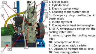
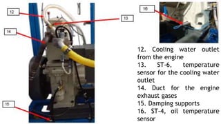
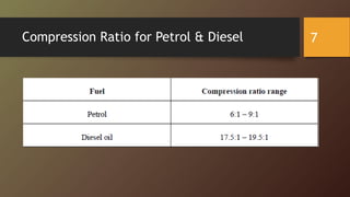
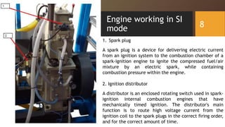
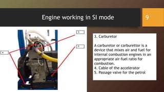
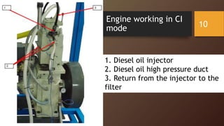
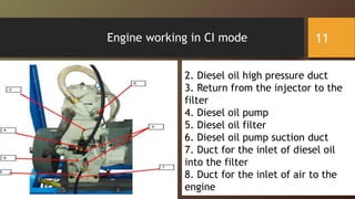
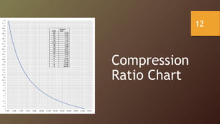
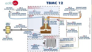
LAB 6: Study the effect of the compression ratio on the
performance and power of an engine (CI&SI), be able to
plot the torque, power and performance curves in
function of the speed for different values of the
compression ratio.
ME-469L (IC Engines and Power Plants Lab)
Umair Munir
Lab Engineer
Water-Cooled Dual Engine [TM12-01]
Engine Specifications
Type of engine Spark ignition/
compression ignition
Maximum power 5.8 kW/1800 rpm CR 18:1
5.7 kW/1800 rpm CR8:1
Fuel Petrol/Diesel Maximum torque 30 N.m
No. of cylinders 1 Type of air intake Naturally aspired
No. of strokes 4 Type of cooling Water
Cylinder bore 87.5 mm Starter Electric
Cylinder stroke 110 mm Compression ratio Variable
2
Study of the effect of the compression ratio on
the performance and power of an engine
• What is Compression Ratio?
Compression ratio is defined as the
ratio between total cylinder volumes
to clearance volume. The higher this
ratio, the greater will be the power
output from a given engine.
3
4
General Description of Single Cylinder
Water Cooled Dual Engine [TM12-01]
5
1. Engine block
2. Cylinder head
3. Electric starter motor
4. Coupling to the starter motor
5. Emergency stop pushbutton in
petrol mode
6. Inertia flywheel
7. Cooling water inlet to the engine
8. ST-7, temperature sensor for the
cooling water inlet
9. Valve to open the cooling water
inlet
10. Decompression lever
11. Compression ratio variator
17. Dipstick to measure the oil level
18. Case venting system
6
12. Cooling water outlet
from the engine
13. ST-6, temperature
sensor for the cooling water
outlet
14. Duct for the engine
exhaust gases
15. Damping supports
16. ST-4, oil temperature
sensor
Compression Ratio for Petrol & Diesel 7
Engine working in SI
mode 8
1. Spark plug
A spark plug is a device for delivering electric current
from an ignition system to the combustion chamber of a
spark-ignition engine to ignite the compressed fuel/air
mixture by an electric spark, while containing
combustion pressure within the engine.
2. Ignition distributor
A distributor is an enclosed rotating switch used in spark-
ignition internal combustion engines that have
mechanically timed ignition. The distributor's main
function is to route high voltage current from the
ignition coil to the spark plugs in the correct firing order,
and for the correct amount of time.
9
Engine working in SI mode
3. Carburetor
A carburetor or carburettor is a
device that mixes air and fuel for
internal combustion engines in an
appropriate air–fuel ratio for
combustion.
4. Cable of the accelerator
5. Passage valve for the petrol
10
Engine working in CI
mode
1. Diesel oil injector
2. Diesel oil high pressure duct
3. Return from the injector to the
filter
11
Engine working in CI mode
2. Diesel oil high pressure duct
3. Return from the injector to the
filter
4. Diesel oil pump
5. Diesel oil filter
6. Diesel oil pump suction duct
7. Duct for the inlet of diesel oil
into the filter
8. Duct for the inlet of air to the
engine
12
Compression
Ratio Chart
Lab Manual 13
Questions 14
15

Lab 10.pptx power plant engineering ic engine

  • 1.
    LAB 6: Studythe effect of the compression ratio on the performance and power of an engine (CI&SI), be able to plot the torque, power and performance curves in function of the speed for different values of the compression ratio. ME-469L (IC Engines and Power Plants Lab) Umair Munir Lab Engineer
  • 2.
    Water-Cooled Dual Engine[TM12-01] Engine Specifications Type of engine Spark ignition/ compression ignition Maximum power 5.8 kW/1800 rpm CR 18:1 5.7 kW/1800 rpm CR8:1 Fuel Petrol/Diesel Maximum torque 30 N.m No. of cylinders 1 Type of air intake Naturally aspired No. of strokes 4 Type of cooling Water Cylinder bore 87.5 mm Starter Electric Cylinder stroke 110 mm Compression ratio Variable 2
  • 3.
    Study of theeffect of the compression ratio on the performance and power of an engine • What is Compression Ratio? Compression ratio is defined as the ratio between total cylinder volumes to clearance volume. The higher this ratio, the greater will be the power output from a given engine. 3
  • 4.
    4 General Description ofSingle Cylinder Water Cooled Dual Engine [TM12-01]
  • 5.
    5 1. Engine block 2.Cylinder head 3. Electric starter motor 4. Coupling to the starter motor 5. Emergency stop pushbutton in petrol mode 6. Inertia flywheel 7. Cooling water inlet to the engine 8. ST-7, temperature sensor for the cooling water inlet 9. Valve to open the cooling water inlet 10. Decompression lever 11. Compression ratio variator 17. Dipstick to measure the oil level 18. Case venting system
  • 6.
    6 12. Cooling wateroutlet from the engine 13. ST-6, temperature sensor for the cooling water outlet 14. Duct for the engine exhaust gases 15. Damping supports 16. ST-4, oil temperature sensor
  • 7.
    Compression Ratio forPetrol & Diesel 7
  • 8.
    Engine working inSI mode 8 1. Spark plug A spark plug is a device for delivering electric current from an ignition system to the combustion chamber of a spark-ignition engine to ignite the compressed fuel/air mixture by an electric spark, while containing combustion pressure within the engine. 2. Ignition distributor A distributor is an enclosed rotating switch used in spark- ignition internal combustion engines that have mechanically timed ignition. The distributor's main function is to route high voltage current from the ignition coil to the spark plugs in the correct firing order, and for the correct amount of time.
  • 9.
    9 Engine working inSI mode 3. Carburetor A carburetor or carburettor is a device that mixes air and fuel for internal combustion engines in an appropriate air–fuel ratio for combustion. 4. Cable of the accelerator 5. Passage valve for the petrol
  • 10.
    10 Engine working inCI mode 1. Diesel oil injector 2. Diesel oil high pressure duct 3. Return from the injector to the filter
  • 11.
    11 Engine working inCI mode 2. Diesel oil high pressure duct 3. Return from the injector to the filter 4. Diesel oil pump 5. Diesel oil filter 6. Diesel oil pump suction duct 7. Duct for the inlet of diesel oil into the filter 8. Duct for the inlet of air to the engine
  • 12.
  • 13.
  • 14.
  • 15.