Download as PDF, PPTX

![Step-5: Capacity of the Weaving Segment
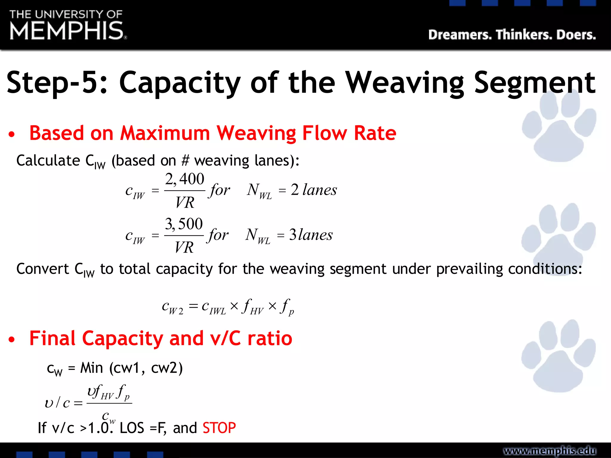
• Based on Breakdown Density
cIWL = cIFL - 438.2(1+VR)1.6
éë ùû + 0.0765LS[ ]+ 119.8NWV[ ]
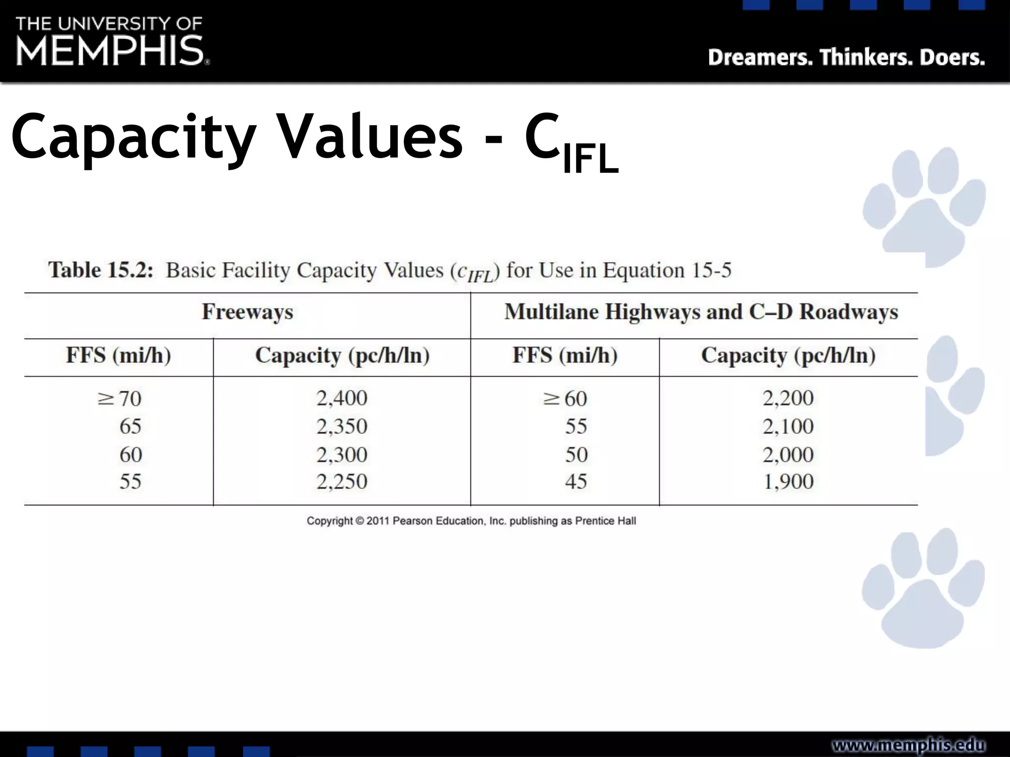
Calculate CIWL (cap per lane of weaving section under ideal conditions:
Convert CIWL to total capacity for the weaving segment under prevailing conditions:
pHVIWLW ffNcc 1](https://image.slidesharecdn.com/l20weavingmergingdivergingmovements-200408174925/75/L20-Weaving-Merging-and-Diverging-Movements-21-2048.jpg)
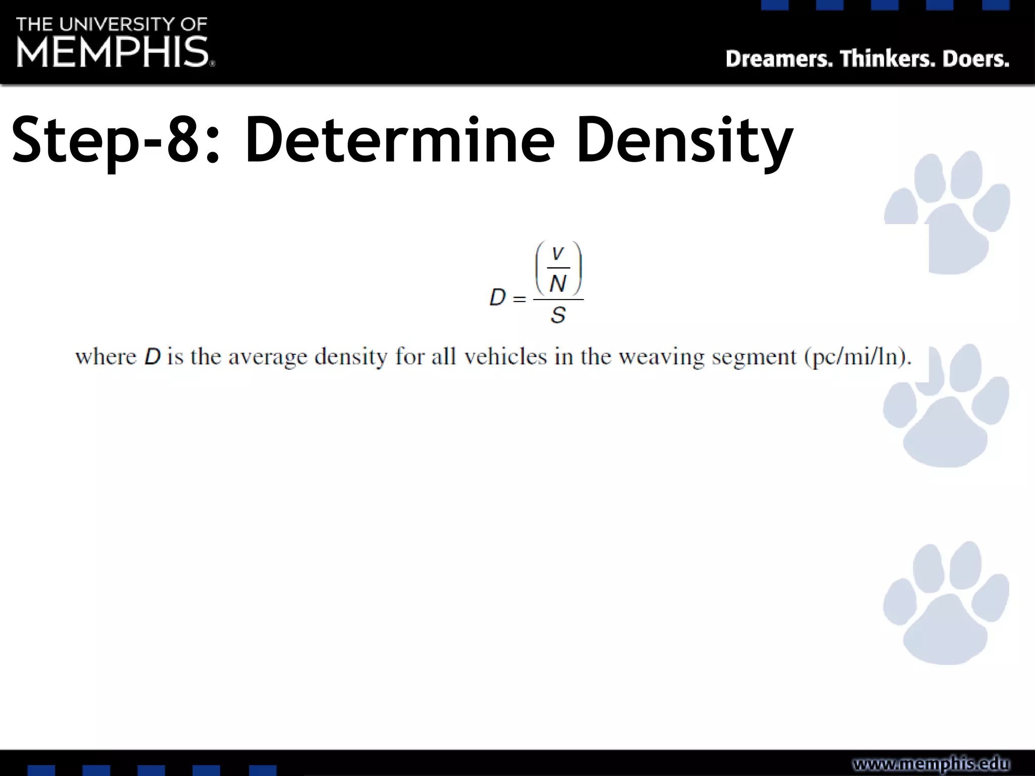
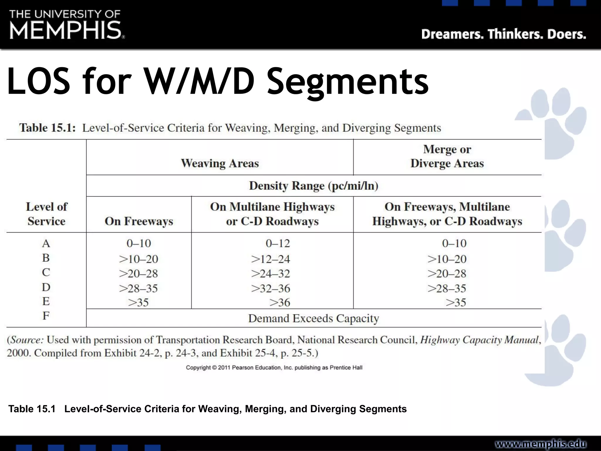
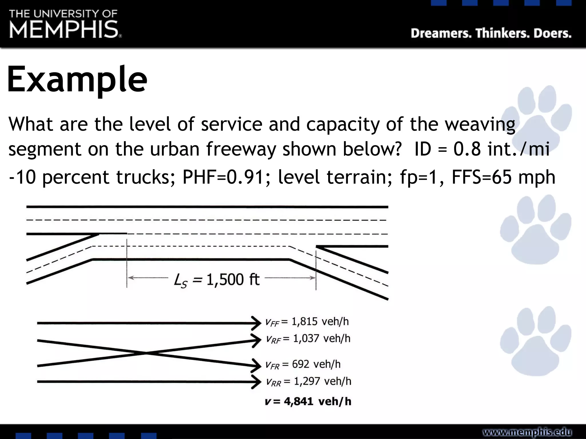
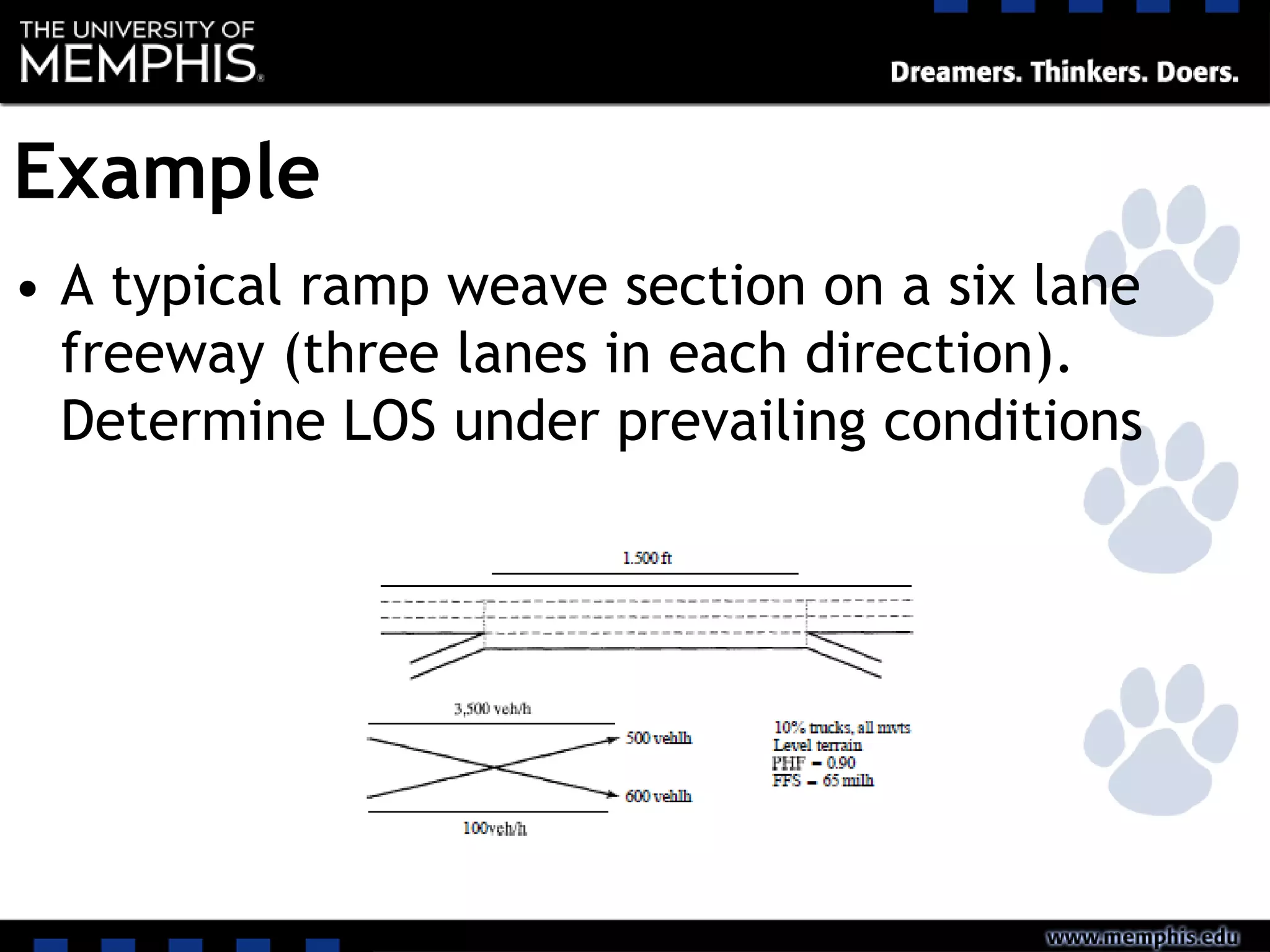

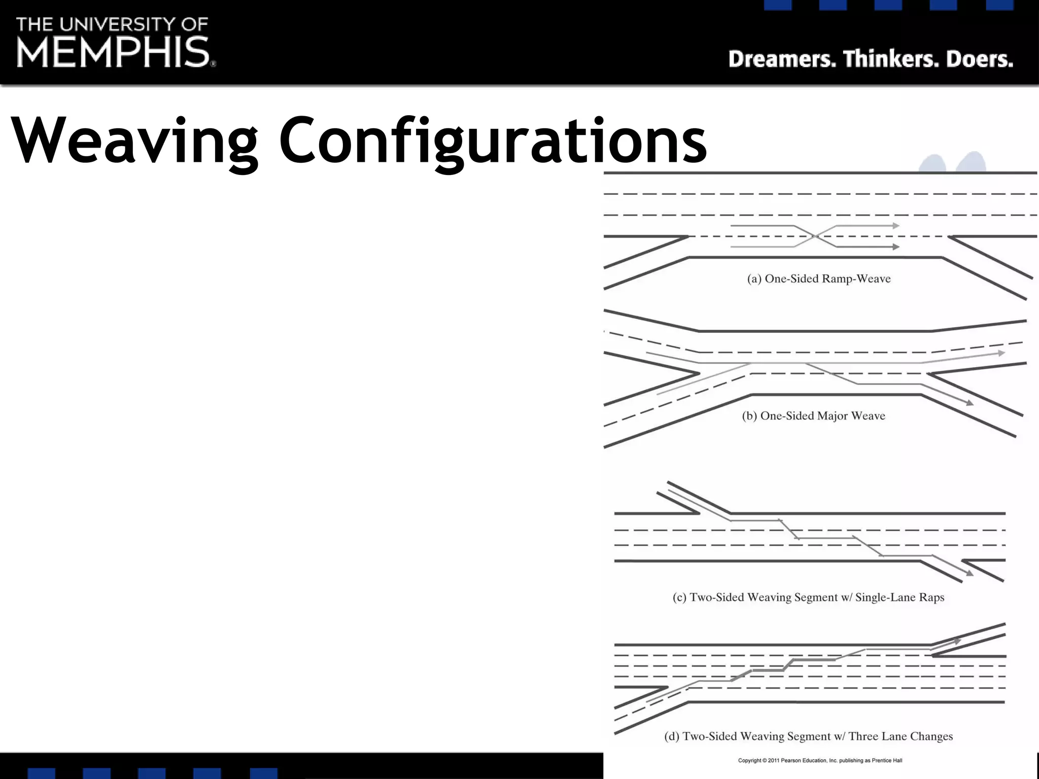
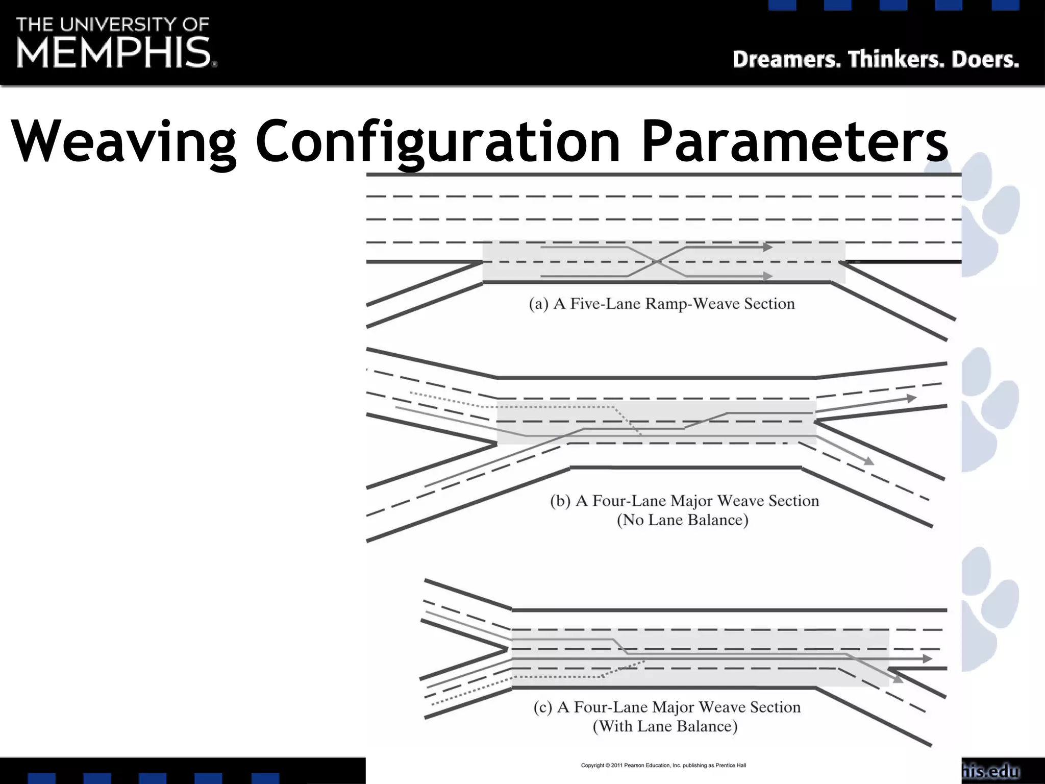
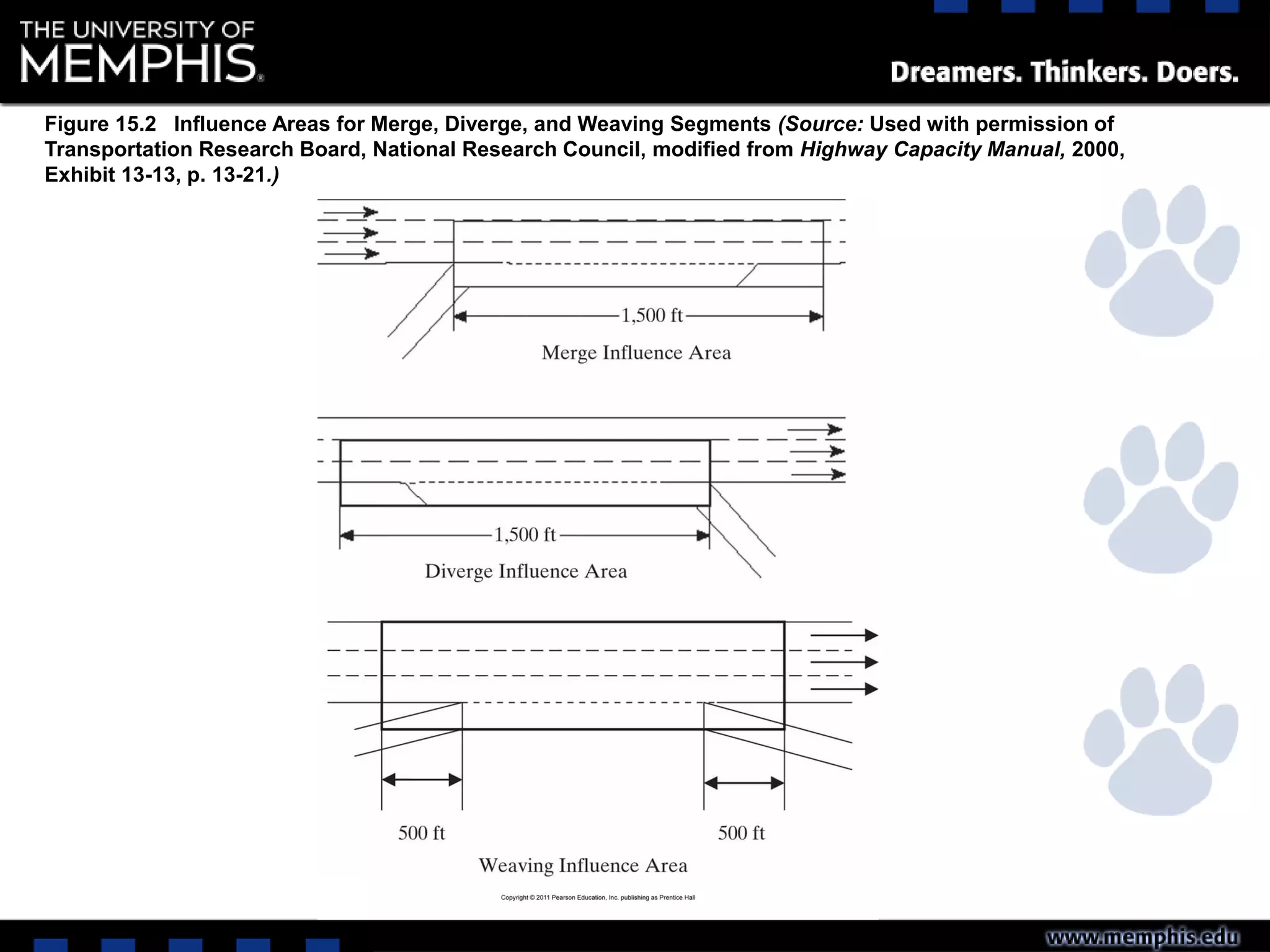
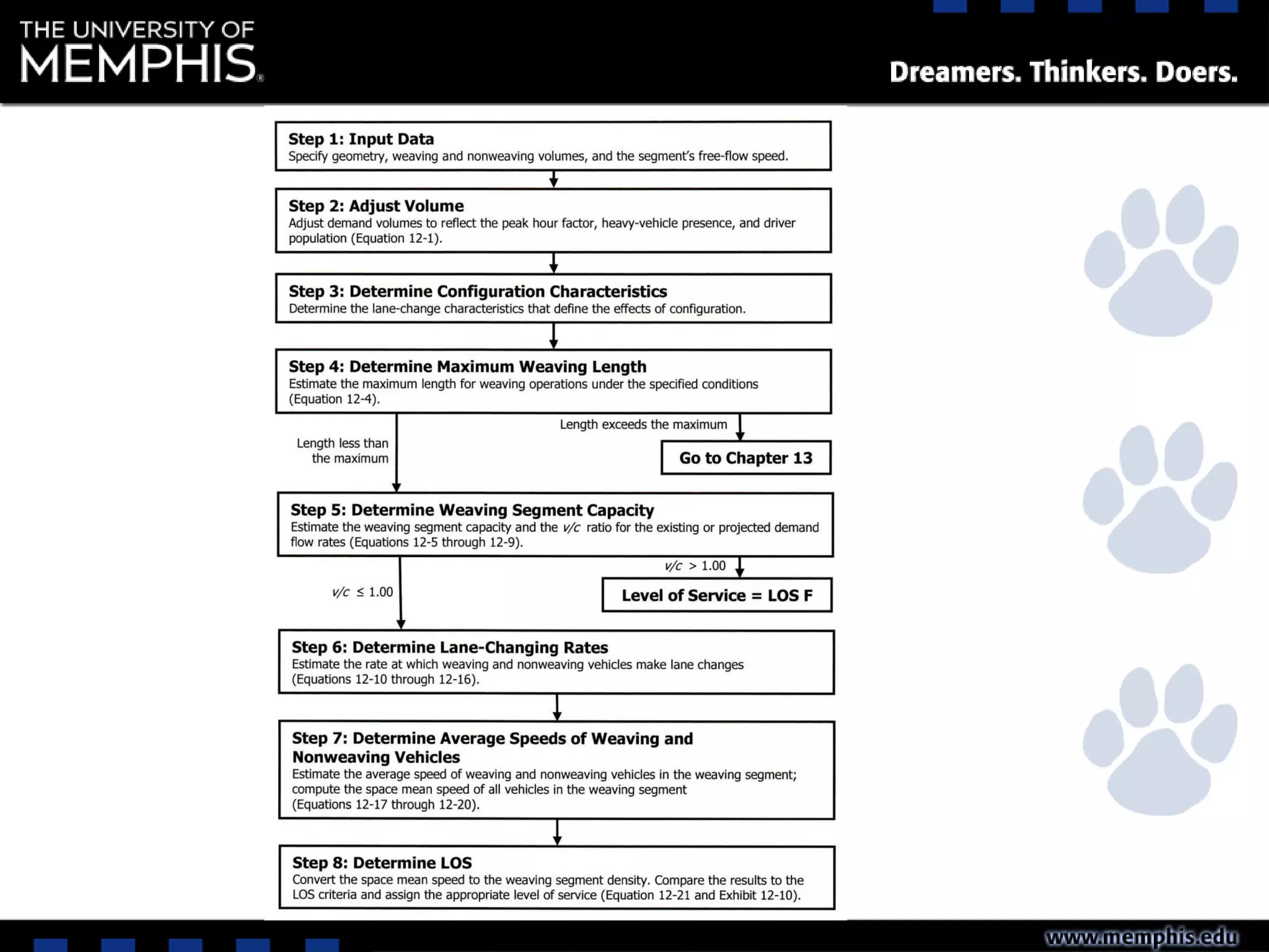
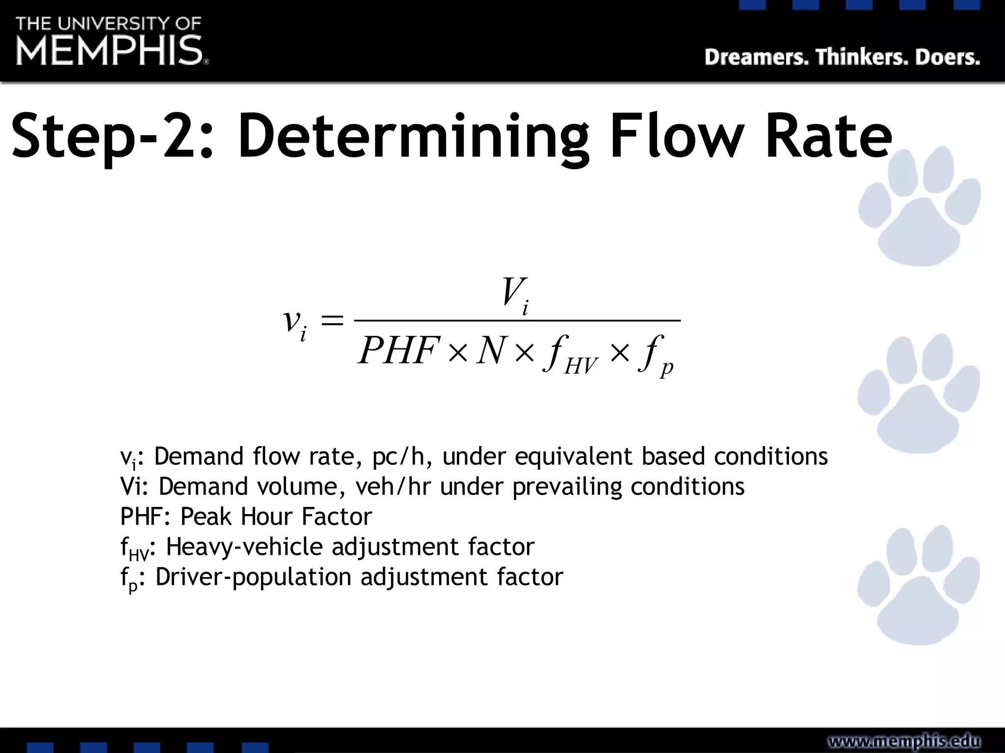
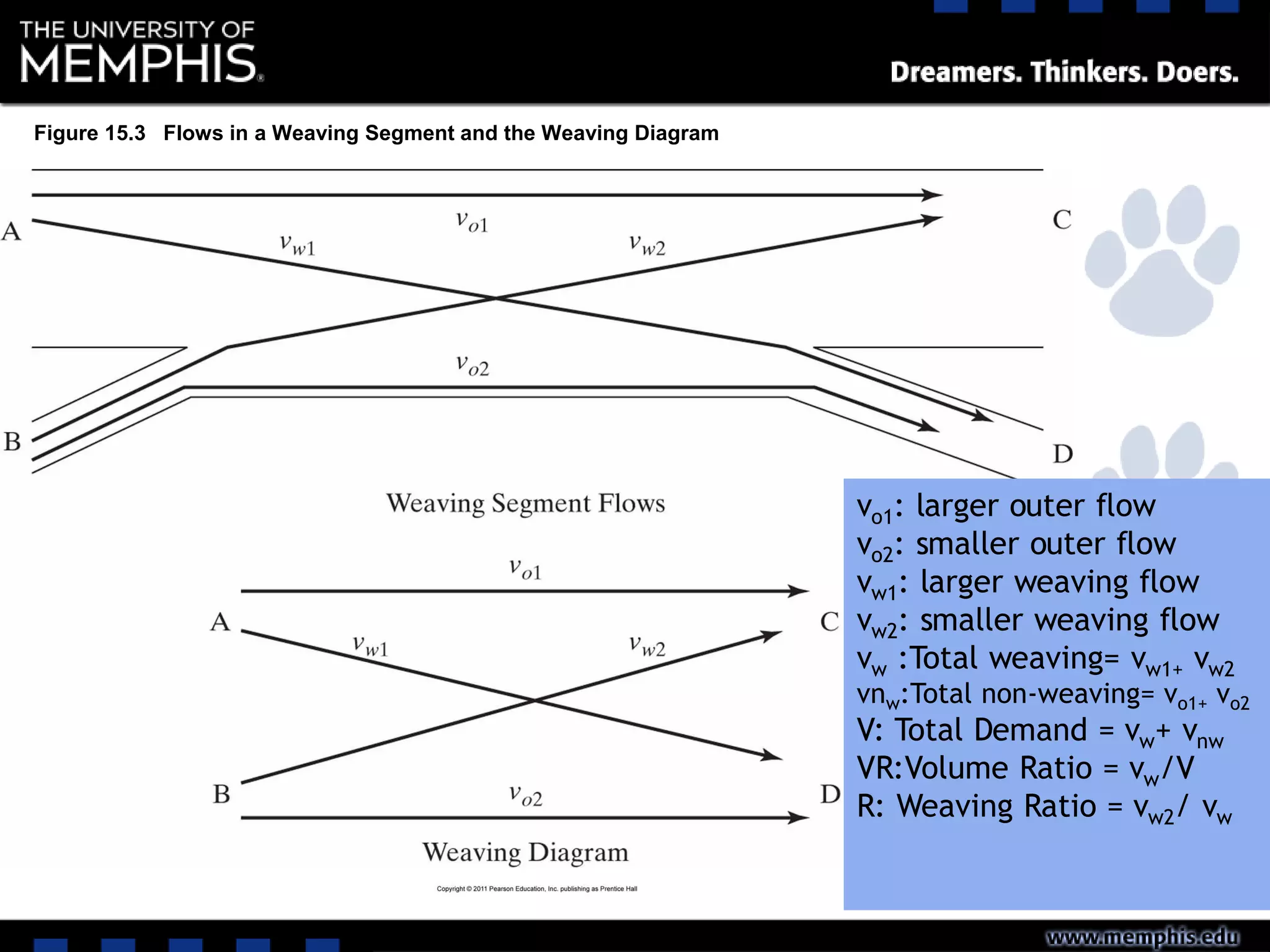
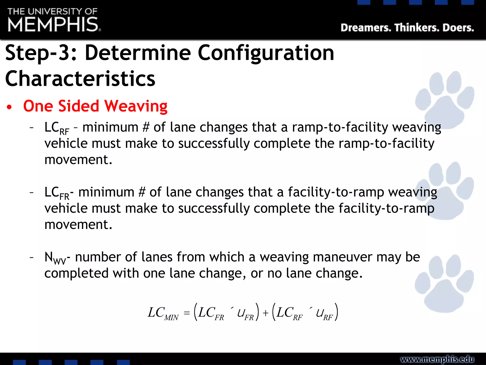
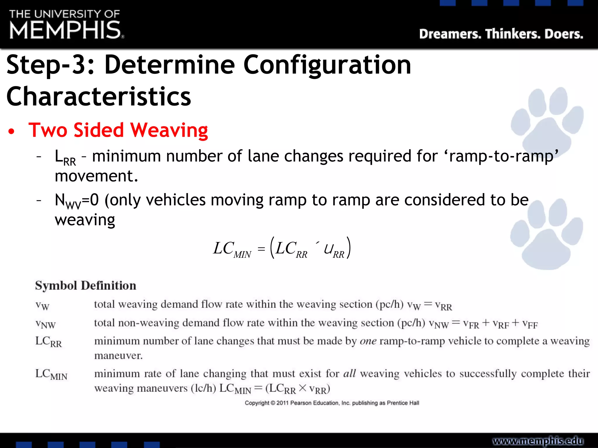
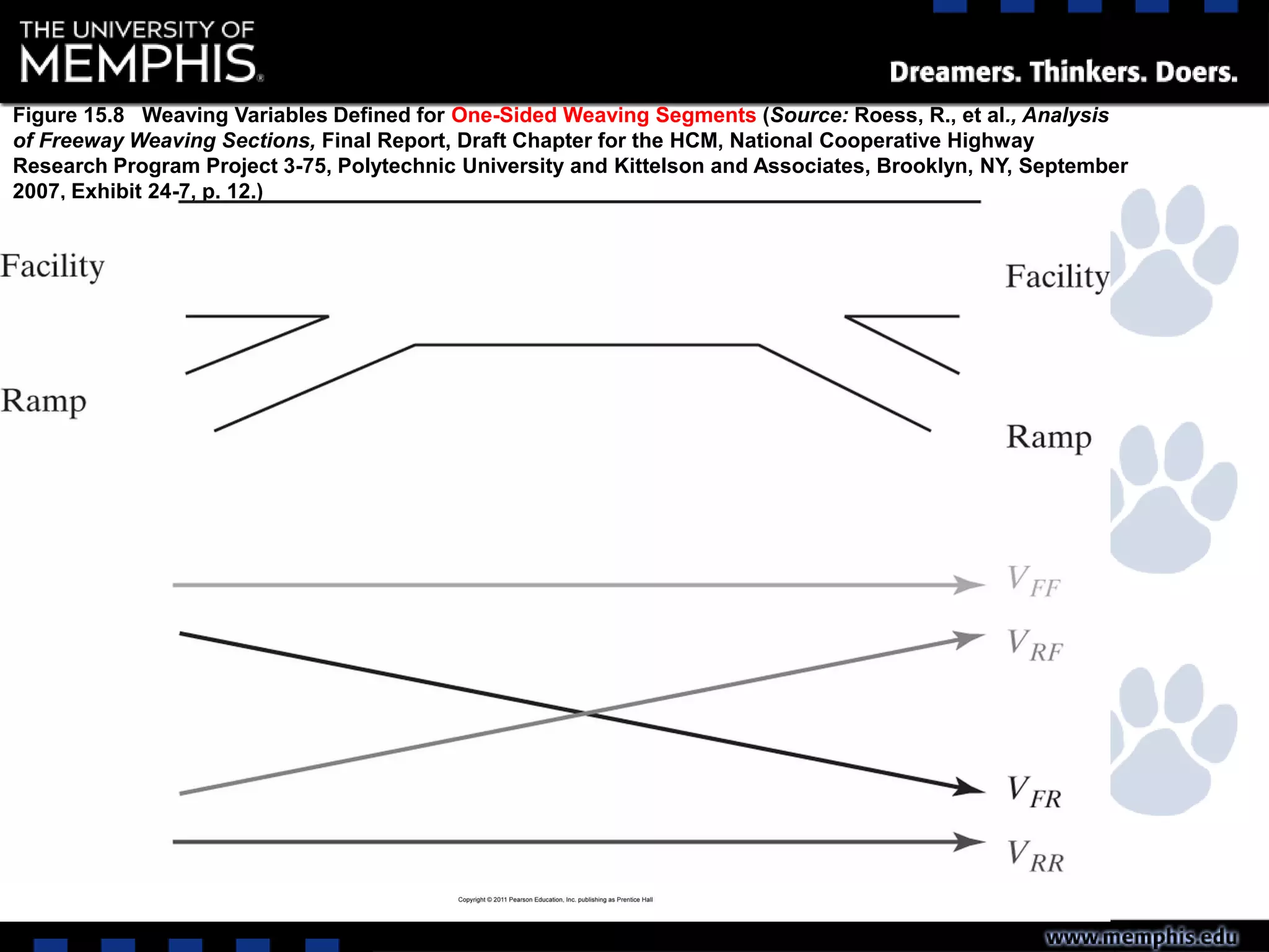
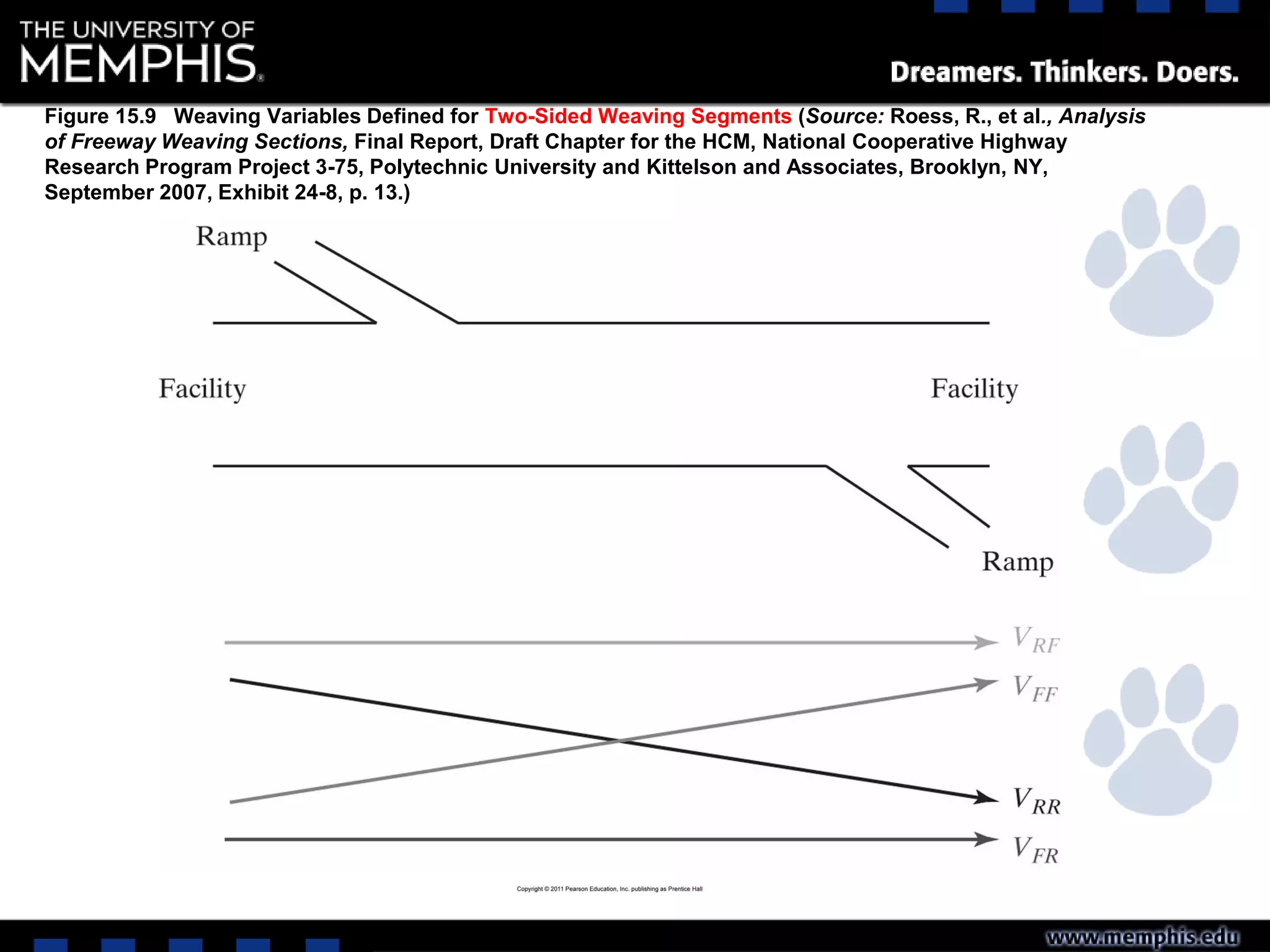
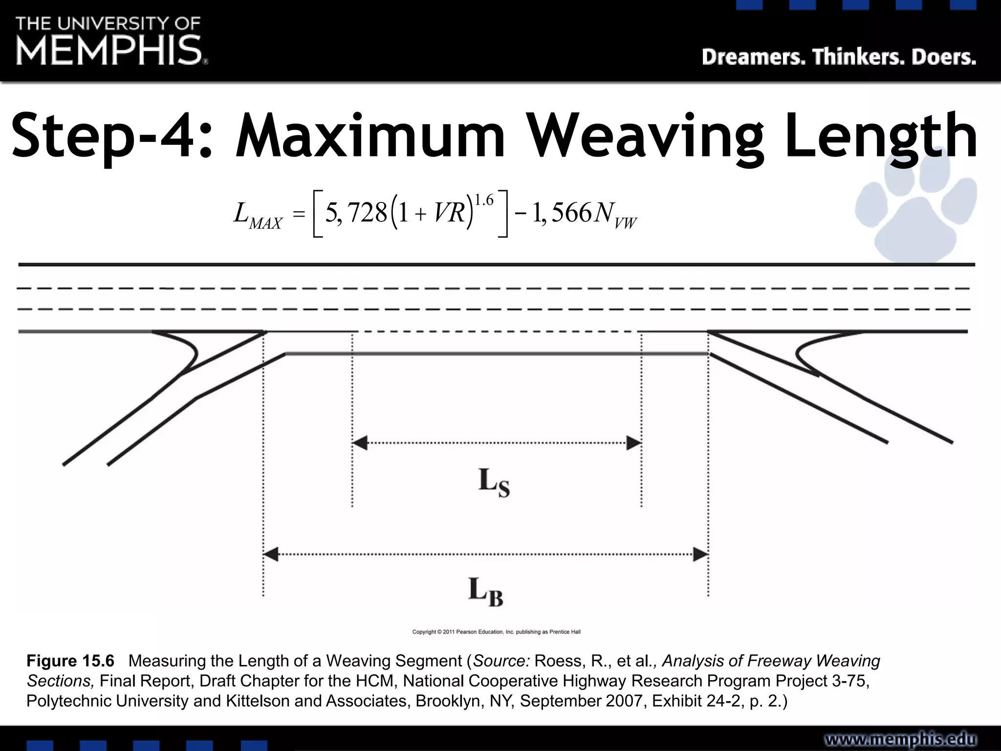
This document describes the process for analyzing and determining the level of service of weaving, merging, and diverging segments on highways. It involves 8 steps: 1) collecting input data, 2) determining flow rates, 3) determining the configuration, 4) calculating maximum weaving length, 5) determining capacity, 6) calculating total lane changing, 7) determining average speed, and 8) calculating density to determine the LOS. An example problem is also provided to demonstrate applying the 8-step process to analyze a weaving segment on an urban freeway.


![10 Geometric Design of Railway Track [Horizontal Alignment] (Railway Engineer...](https://cdn.slidesharecdn.com/ss_thumbnails/geometricdesignofrailwaytrack-i-200415171932-thumbnail.jpg?width=640&height=640&fit=bounds)

![11 Geometric Design of Railway Track [Vertical Alignment] (Railway Engineerin...](https://cdn.slidesharecdn.com/ss_thumbnails/geometricdesignofrailwaytrack-ii-200415172410-thumbnail.jpg?width=640&height=640&fit=bounds)


