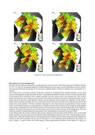
The document summarizes the results of a detailed flow investigation within a centrifugal pump equipped with a vaned diffuser. Unsteady velocity measurements were obtained in the impeller and diffuser at different radial planes. The analysis shows the presence of a complex, unsteady and periodic jet-wake flow structure in the impeller. At the impeller discharge, the mixing of the unsteady flow entering the diffuser is affected by the diffuser vanes, though periodic flow characteristics are still observed at the diffuser throat, indicating unsteady inlet conditions for the diffuser.
This presentation had been prepared for the aircraft propulsion class to my undergraduate and graduate students at Kasetsart University and Chulalongkorn University - Bangkok, Thailand.
Investigation of buffet control on transonic airfoil by tangential jet blowingМурад Брутян
Two-dimensional steady-state and unsteady numerical simulations are carried out in the framework of
Reynolds averaged Navier-Stokes equations to characterize the buffet phenomenon on supercritical
transonic airfoil. Tangential jet blowing is investigated to delay buffet onset on the airfoil. In this case,
the jet of compressed air is blown continuously from small slot nozzle tangentially to wing upper
surface in the region of shock location to reduce shock-induced separation.
Experimental investigation of damping force of twin tube shock absorberIJERA Editor
A shock absorber is a mechanical device to damp shock impulse and convert kinetic energy into thermal energy. The damping effect of shock absorber depends on damping force and damping force is affected by various process parameters. In this analysis three process parameters damping diameter(A), number of holes(B) and suspension velocity(C) were considered and their effect on damping force of shock absorber was studied and accordingly suitable orthogonal array was selected by taguchi method. Experiment conducted on servo hydraulic testing machine and after conducting experiments damping force was measured and with the help of S/N ratio, ANOVA, Regression analysis optimum parameter values can be obtained and confirmation experiments was carried out. Twin tube shock absorber was used to carry out experimentation.
Investigation on Divergent Exit Curvature Effect on Nozzle Pressure Ratio of ...IJERA Editor
The objective of this project work is to computationally analyze shock waves in the Convergent Divergent (CD) Nozzle. The commercial CFD code Fluent is employed to analyze the compressible flow through the nozzle. The analysis is about NPR (Nozzle Pressure Ratio) i.e., the ratio between exit pressure of the nozzle to ambient pressure. The various models of CD Nozzle are designed and the results are compared. The flow characteristic of shockwave for various design of CD Nozzle is also discussed. The purpose of this project is to investigate supersonic C-D nozzle flow for increasing NPR (Nozzle pressure ratio) through CFD. The imperfect matching between the pressures and ambient pressure and exit pressure leads to the formation of a complicated shock wave structure. Supersonic nozzle flow separation occurs in CD nozzles at NPR values far above their design value that results in shock formation inside the nozzle. The one-dimensional analysis approximations are not accurate, in reality the flow detaches from the wall and forms a separation region, subsequently the flow downstream becomes non-uniform and unstable. Shock wave affects flow performance of nozzle from NPR value 1.63 for existing geometrical conditions of nozzle. Problem of using this nozzle above 1.63NPR is shock wave at downstream of throat. After shock wave, static pressure increases further downstream of flow. It leads to flow separation and back pressure effects. Back pressure makes nozzle chocked. To investigate this problem, geometry of divergent portion is introduced and analysed through CFD. This is expected in resulting of reduction of flow separation and back pressure effect as well as increase in nozzle working NPR.
An Investigation on the Performance Characteristics of a Centrifugal CompressorIJERD Editor
The design and off-design performance characteristics of single stage centrifugal compressor
consisting of 12 vanes impeller interfacing with 11 vanes diffuser have been studied experimentally and
numerically. The impeller has been designed and developed with radial exit, 30o inlet blade angle (with
tangent), 77 mm diameter and the discharge volute considering constant mean flow velocity. The performance
of the compressor at varying capacity (60 to 120 % of design) by controlling the discharge valve and with the
variation of rotating speed (15000 to 35000 rpm) by regulating speed of the coupled gas turbine has been
conducted at the recently developed test rig. The numerical simulation has been done by adopting viscous
Reynolds Average Navier-Stokes (RANS) equations with and without Coriolis Force & Centrifugal Force in
rotating reference frame (impeller) and stationary reference frame (casing) respectively utilizing CFD software
Fluent 14. The flow around a single vane of impeller interfacing with single vane of diffuser, the rotational
periodicity and sliding mesh at the interfacing zone between rotating impeller and stationery diffuser are
considered. Non dimensional performance curves derived from experimental and numerical results are
presented and compared. The numerical results are found to match very closely with the experimented data near
the design point and deviation is observed at the both side of the designed operating point. Non-uniform
pressure profiles towards the impeller exit and strong cross flow from blade to blade are detected at low flow
operating conditions. Total pressure, static pressure and velocity distributions at design and off design
operation obtained from the CFD results are analysed and presented here.
Influence of number of impeller and diffuser blades on the pressure recovery ...eSAT Journals
Abstract Impeller is a very important element in rotating devices to deliver energy to/from the fluid. The diffusers are essential for effective transformation of the kinetic power produced by the rotor in a centrifugal fan. Hence the flow in the impeller and diffuser passages is the important phenomenon in optimizing the performance. These impeller and diffuser flow passages are the most complex regions to predict the flow behavior. With the advanced development of Particle Image Velocimetry as well as convenient numerical CFD tools, it has become possible to reach at an accurate result well-matched with the real behavior of the flow. Hence, in this work moving mesh technique is used to get a numerical solution for the estimation of actual flow manner. Numerous research works have been done recently to get the physics of fluid flow through impeller and diffuser, both numerically and experimentally. But it is found from the literature that the study on the performance of the fan by changing the number of impeller and diffuser blades together in a combination has not been the emphasis of attention in these works. Hence a numerical analysis has been carried out in this paper to comprehensively lookout the fluid interaction in impeller-diffuser as well as to envisage the flow behavior of the fan by changing the number of impeller and diffuser blades together in combination. For the same number of impeller blades, it is found from the analysis that a higher static pressure rise coefficient is achieved at the outlet of the fan for smaller number of diffuser blades. It is also found that larger the number of impeller blades, larger is the static pressure rise coefficient for the same number of diffuser blades, hence performance gets improved. Key Words: Unsteady flow, Recirculation zone, Turbulence, Impeller vane, Diffuser vane, Static pressure rise.
COMPUTATIONAL ANALYSIS OF FLUID FLOW THROUGH ROTATING VANELESS DIFFUSERIjripublishers Ijri
The main objective of the work is to analyze the behavior of the fluid flow through a rotating vaneless diffuser,
flow near wall conditions, performance characteristics and means to reduce the flow losses in a centrifugal
compressor. The project presents a numerical procedure to investigate the pressure distortion at
exit flow of impeller and flow fields around impeller blade and to validate computational results against experimental
data with various models. In rotating vane less diffuser, there are various concepts. The concept
of blade cut back is to be employed in back ward curved impeller to obtain the rotating vaneless diffuser,
which rotates with the speed of the centrifugal impeller and the performance parameters is to be compared
with the static vane less diffuser.
This work was aimed at developing a computational model following certain standards that are important to turbo machinery. Numerical and experimental investigations have been carried out on a two bladed savonius rotor by varying certain parameters of the turbine namely blade shape, blade profile, aspect ratio of the turbine and position of vent on the blade. For numerical investigation, commercial computational fluid dynamic (CFD) software ANSYS-FLUENT has been used. The results obtained have been validated with established experimental results. Investigations involving the variation of Aspect ratio have been done completely through experimentation. For the other cases, the obtained numerical results have been validated with the established experimental values. For the investigation regarding variation of blade shape, the length of semi minor axis has been changed and simulations have been carried out. Also, in the blade a vent has been introduced and its best position determined. Finally, new blade shapes have been designed and simulations carried out to find the optimum one. All these cases were computed at two different Reynolds number specifically 150000 and 80000. The new configurations gave better results than that for the conventional one.
The turbo machine is an energy conversion device which converts mechanical energy to kinetic/pressure energy or vice versa. The conversion is done through the dynamic interaction between a continuously flowing fluid and rotating machine component. Turbo machines comprise various types of fans, blowers, compressors, pumps, turbines etc. More and more experimental research work is available in the field of turbo machine design and its evaluation. Literature review has revealed that a few literatures are available on three dimensional numerical analysis of a centrifugal fan/blower. Literature review in present work is highly focused on centrifugal blower and use of CFD techniques in turbo machines. In this course of work, input parameters and design parameters of centrifugal blower is obtained as per church and Osborne design methodology developed by Kinnari Shah, PROF. NitinVibhakar. Fluid model is made as per this design data in PRO-E SOFTWARE. And this fluid model is simulated using computational fluid dynamics (CFD) approach in ANSYS (CFX). Numerical analysis carried out in this work is to understand the flow characteristics at design and off-design conditions under varying mass flow rates, varying rotational speeds and number of blades in both design methodology. This numerical analysis is under consideration of steady flow and for rotational domain (frozen rotor interference) is used. Performance curves are obtained under different variable inlet parameters like volume flow rate, rotational speed and number of impeller blades. Here mass flow rate as a inlet boundary condition and static pressure as a outlet boundary condition. Volume flow rate is changed by changing the mass flow rate at inlet. Overall work carried out on flow behaviour and performance graphs for different cases are discussed in length in results and discussions chapter. Comparative evaluation of two design method indicates that error in static pressure gradient is higher in Osborne design rather than church design, and performance parameters are better for church design than the Osborne design.
The effect of rotational speed variation on the velocity vectors in the singl...IOSR Journals
The current investigation is aimed to simulate the three-dimensional complex internal flow in a
centrifugal pump impeller with five twisted blades by using a specialized computational fluid dynamics (CFD)
software ANSYS /FLUENT 14code with a standard k-ε two-equation turbulence model.
A single blade passage will be modeled to give more accurate results for velocity vectors on (blade, hub, and
shroud). The potential consequences of velocity vectors associated with operating a centrifugal compressor in
variable rotation speed.
A numerical three-dimensional, through flow calculations to predict velocity vectors through a
centrifugal pump were presented to examined the effect of rotational speed variation on the velocity vectors of
the centrifugal pump . The contours of the velocity vectors of the blade, hub, and shroud indicates low velocity
vectors in the suction side at high rotational speed (over operation limits )and the velocity vectors increases
gradually until reach maximum value at the leading edge (2.63×10 m/s) of the blade
Transient flow analysis for horizontal axial upper-wind turbineinventy
This study is to carry out a transient flow field analysis on the condition that the wind turbine is working to generate turbine, the wind turbine operating conditions change over time, Purpose of this study is try to find out the rule from the wind turbine changing over time . In transient analysis, the wind velocity on inlet boundary and rotation speed in the rotor field will change over time, and an analytical process is provided that can be used for future reference. At present, the wind turbine model is designed on the concept of upwind horizontal axis type. The computer engineering software GH Bladed is used to obtain the relationship between the rotor velocity and the wind turbine. Then the ANSYS engineering software is used to calculate the stress and strain distribution in the blades over time. From the analytical result, the relationship between the stress distribution in the blades and the rotor velocity is got to be used as a reference for future wind turbine structural optimization.
Brimmed diffuser is collection�acceleration device which shrouds a wind turbine.For a given turbine di ameter,the power augmentation can be achieved by brimmed diffuser,p opularly known as wind lens. The present numerical investigation deals with the effect of low pressure region created by wind l ens and hence to analyze the strong vortices formed by a brim attached to the shroud diffuser at exit. Also in this analysis,a c omparative numerical prediction of mass flow rates through the wind turbine has been carried out with various types of wind lens wh ich in turn helps to optimize the torque augmentati on. It has been numerically proved that there is significant increase in the wa ke formation & vortex strength when brimming effect is added to a diffuser
This paper deals with the numerical analysis of 3d model which has inlet port diameter 46mm,valve diameter 43mm and the length and diameter of the cy linder is 562mm and 93.65mm respectively which is developed to study the effect of valve lif t on the flow of fluid inside the cylinder. For different valve lifts velocity will change inside t he cylinder. Results of CFD simulation indicated th at valve lift affects velocity flow field inside the c ylinder. It also proved that CFD is a convenient to ol for designing and optimizing the flow field in the engine.
3D FLOW ANALYSIS OF AN ANNULAR DIFFUSER WITH AND WITHOUT STRUTS IAEME Publication
Numerical investigations have been carried out for an annular type gas turbine exhaust diffuser with inlet guidevanes and with and without struts. Numerical simulations were carried out to determine the pressure recovery coefficient, for a divergence angle 13o by keeping the diffusion length constant. The flow conditions at the inlet are varied to evaluate how they affect the flow development in the passage. The velocity at inlet is varied from 80 m/s to 160 m/s in the steps of 40 m/s. In the present study a (1/6)th part of the model is considered for the analysis, due to symmetry. The results for with and without struts indicates how the pressure recovery coefficient affects the efficiency of the turbine.
Investigation on Divergent Exit Curvature Effect on Nozzle Pressure Ratio of ...IJERA Editor
The objective of this project work is to computationally analyze shock waves in the Convergent Divergent (CD) Nozzle. The commercial CFD code Fluent is employed to analyze the compressible flow through the nozzle. The analysis is about NPR (Nozzle Pressure Ratio) i.e., the ratio between exit pressure of the nozzle to ambient pressure. The various models of CD Nozzle are designed and the results are compared. The flow characteristic of shockwave for various design of CD Nozzle is also discussed. The purpose of this project is to investigate supersonic C-D nozzle flow for increasing NPR (Nozzle pressure ratio) through CFD. The imperfect matching between the pressures and ambient pressure and exit pressure leads to the formation of a complicated shock wave structure. Supersonic nozzle flow separation occurs in CD nozzles at NPR values far above their design value that results in shock formation inside the nozzle. The one-dimensional analysis approximations are not accurate, in reality the flow detaches from the wall and forms a separation region, subsequently the flow downstream becomes non-uniform and unstable. Shock wave affects flow performance of nozzle from NPR value 1.63 for existing geometrical conditions of nozzle. Problem of using this nozzle above 1.63NPR is shock wave at downstream of throat. After shock wave, static pressure increases further downstream of flow. It leads to flow separation and back pressure effects. Back pressure makes nozzle chocked. To investigate this problem, geometry of divergent portion is introduced and analysed through CFD. This is expected in resulting of reduction of flow separation and back pressure effect as well as increase in nozzle working NPR.
International Journal of Computational Engineering Research (IJCER) is dedicated to protecting personal information and will make every reasonable effort to handle collected information appropriately. All information collected, as well as related requests, will be handled as carefully and efficiently as possible in accordance with IJCER standards for integrity and objectivity.
1. 2
The Internal Flow Investigation of a Centrifugal Pump
by
A. Akhras, M. El Hajem, R. Morel, J.Y. Champagne
Laboratoire de Mécanique des Fluides
Bât 302, 20 av. A. Einstein, 69621 Villeurbanne; France
ABSTRACT
This paper provides the results of a detailed flow investigation within a centrifugal pump equipped with a vaned
diffuser. The measurements made with a laser-Doppler velocimeter were carried out at the impeller design point. In a
previous paper concerning the same machine, El Hajem (1998) found a jet-wake structure developing at the impeller
exit. During the actual study, measurements were obtained in the impeller and the diffuser at different measuring planes
relative to the diffuser vanes. Results are presented as animations reconstituting a temporal evolution of the flow at the
diffuser inlet.
Unsteady velocity measurements obtained in phase with the impeller angular position gave access to the flow inside the
impeller channels where three sections were explored. For each section, results were obtained as a function of the
position of impeller blades relative to the diffuser vanes. Thus time resolved details of the flow could be examined for a
better understanding of the complex unsteady flow existing between the two interacting blade rows.
The analysis of the impeller flow field indicates the presence of a complex, unsteady and periodic flow. It is organised
in a jet-wake structure. The wake is characterised by low relative velocities and is localised in the suction side/shroud
corner. At this flow rate, it seems that presence of the vanes has only a limited effect on the impeller flow structure,
except when the blades suction side are facing the diffuser vanes.
At the impeller discharge, the time-resolved sequences show that the mixing process of the unsteady and periodic flow
leaving the impeller is affected by the presence of the diffuser. At the leading edge, at the suction side of diffuser vanes,
the flow is rapidly mixed. Whereas, when approaching the diffuser throat, the flow still shows its periodic character
observed at the impeller outlet. This indicates that the diffuser is subject to unsteady inlet conditions that can alter its
performances.
2. 3
I INTRODUCTION
During the design of a turbomachine, the flow is considered steady and uniform at the entry of each element. For a
centrifugal pump with a vaned diffuser, satisfying this assumption requires a large interface between the rotor and the
stator so that the mixing process of the flow leaving the impeller can take place. Otherwise, the unsteady flow that
enters the diffuser represents a source of low efficiency. Furthermore, the internal flow of the impeller can be affected
by asymmetric downstream conditions, which results in extra flow unsteadiness and instabilities. A number of authors
have treated the problem of the interaction of the impeller and its surrounding. Miner [1] used a laser velocimeter to
measure velocities within the impeller and the volute of a centrifugal pump and found that the relative velocity
components distribution varies with the circumferential angle relative to the volute cutwater. Liu (1994) has also used
LDA for the internal flow investigation and found that the asymmetric volute alters the relative flow, the flow rate from
each impeller passage varied with the volute circumferential position by up to 25 percent at an off-design flow rate.
Inoue (1984), Sideris (1987) and Arndt (1989, 1990) have been concerned with the action of the diffuser. For internal
flow studies, a large number of the experimental investigations that revealed the presence of a jet-wake structure at the
discharge of centrifugal rotors was concerned with compressors as done by Eckardt (1975, 1976), Johnston (1976),
Johnson (1978), and more recently Rohne (1991) and Ubaldi (1993). However, Krain (1988) found a velocity profile
that differed widely from the jet-wake type flow. In a previous study, the authors (El Hajem et al., 1998) found a jet-
wake structure developing at the impeller exit During this study, LDA measurements, revealed the presence of a jet-
wake flow structure. The location and the extension of the wake seem to be affected by the proximity of the diffuser
vanes.
II EXPERIMENTAL SETUP
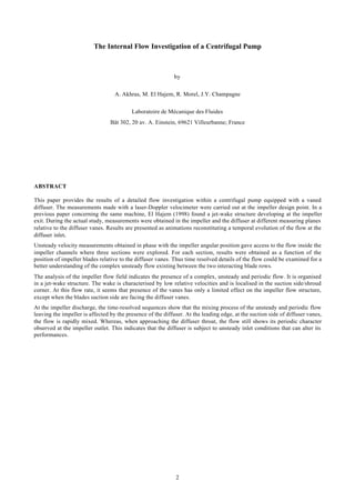
II.1 THE SHF IMPELLER
The test impeller, shown in Figure 1, is a low specific speed (ωs=0.577) shrouded impeller. It has seven backswept
blades with an exit angle of 22.5 degrees relative to the tangential direction. The main geometric data of the impeller
and its operating conditions are resumed in table 1. For optic access, the shroud was made out of clear Plexiglas and a
clear window was realized on the casing. The impeller was run with a vaned diffuser and a spiral casing of industrial
type. The diffuser is a straight wall constant width with six vanes (Figure 1). The main dimensions of the diffuser are
listed in table 2.
II.2 TEST RIG
Experiments were performed on a centrifugal pump test facility (1, figure 2) consisting of a closed rig equipped for the
overall performance characterization of the machine. Water enters the impeller through a straight suction pipe of 1.4 m
in length. The net flow rate traversing the pump is measured by an electromagnetic flow meter (11, figure 2) with a
precision of 0.2 percent at the actual experimental conditions. The impeller is driven by a variable speed DC motor of
45 kW power at 1500 rpm mounted in balance mode for torque measurement (10, figure 2).
Figure 1 : Test impeller and vaned diffuser Figure 2 : Test rig Measuring equipment
3. 4
Table 1 Impeller characteristics
impeller parameter description
R1 = 98.25 mm inlet blade radius at the shroud
R2 = 177.25 mm impeller exit radius
b = 26.7 mm blade height
Z = 7 blade number
β2 = 22.5 deg. blade angle
Qn = 0.0774 m3
/s design flow rate
N = 1188 Rpm rotational speed
φ = 0.118 Design flow coefficient
ψ = 0.481 Design head coefficient
ω = 0.577 specific speed
Table 2 Diffuser characteristics
diffuser parameter description
R3 = 182 mm diffuser inlet radius
R4 = 199.3 mm Leading edge radius
R5 = 258 mm diffuser exit radius
b3 = 28.1 mm Diffuser width
Z = 6 Vane number
α3 = 12 deg. Vane angle
Table 3 Measuring Sections
Angular position
in the diffuser
pitch
α (deg)
r* = r/R2
0.8182
0.9092In the impeller
0.9784
1.0179
1.0451
1.0846
1.1298
I
II
III
IV
V
VI
VII
0 (or 60)
10
17
30
43
50
57
In the Diffuser
1.198
Figure 3 : Research centrifugal pump with LDA optics
Figure 4 : Optic access to the measuring vane
II.3 MEASURING EQUIPMENT
Measurements of velocity distribution at the impeller discharge and in the diffuser were obtained by using an LDA
system. The light source is a 5 W argon ion laser operating in multiline mode in order to operate with the blue (488 nm)
and green (514.5 nm) wavelengths. Modular optics with a 310 mm focusing lens are used to derive a three beam
configuration. The LDA system was used in a back-scatter mode. The optical components, including the laser and the
photomultipliers, were mounted on a three axis traversing system to place the probe volume at the location of interest
(figures 3, 4).
To relate the velocity measurement to the angular position of the impeller, an optical encoder is used to synchronize
measurement with machinery. The encoder fixed on the pump shaft gives the position of the measuring point in the
blade-to-blade plane with a resolution of 3600 angular readings for one shaft revolution.
For each test point M in the axial direction, an average of 10 000 data points were taken. The sampling rate was
arbitrary and depended on the nature of the LDA signals. The data processing system, consisting of two burst signal
analyzers with built-in synchronization inputs for cyclic phenomena, is connected to a PC. A software uses encoder
pulses to phase-sort the velocity samples versus the phase angle. The Data is also phase-averaged to compute the mean
velocity and the turbulence intensity.
In order to study the interaction of the impeller and the diffuser, the flow was investigated at 7 radial planes located at
different angular positions in the diffuser as given on table 3 and shown on figure 5. For each plane, the flow was
investigated at eight radial sections in the impeller and the diffuser (table 3), for each radii, sixteen points were
explored.
4. 5
Figure 5 : Locations of the measurement planes within the impeller and the diffuser
0 90 180 270 360
Angular position (deg)
0
5
10
15
20
Cr,Cu(m/s)
Cr
Cur/R2 = 0.818
z/b = 0.5
0 90 180 270 360
Angular position (deg)
0
5
10
15
20
Cr,Cu(m/s)
Cr
Cur/R2 = 0.909
z/b = 0.5
0 90 180 270 360
Angular position (deg)
0
5
10
15
20
Cr,Cu(m/s)
Cr
Cur/R2 = 0.978
z/b = 0.5
Figure 6 : Fluctuating velocity at the impeller channels, plane I, z/b = 0.5
III DISCUSSION OF THE EXPERIMENTAL RESULTS
The laser Doppler velocimeter used for internal flow investigation is two dimensional, only the velocity components in
the radial and circumferential directions were measured; the velocity in the axial direction was not measured and was
supposed to be negligible.
III.1 VELOCITY FLUCTUATIONS OF THE IMPELLER INTERNAL FLOW
The absolute velocity is presented as a function of the angular position within the impeller channels and the axial
distance z/b. The shroud and the hub are located at z/b=0 and z/b=1 respectively (Figure 6). field evolution at the
nominal flow rate. The reported results correspond to the measurements obtained at passage midheight (z/b=0.5) for
three sections corresponding to r/R2= 0.818, 0909 and 0.978. In these figures, the same velocity distribution repeated
over seven periods corresponds to the flow in the seven impeller channels; it illustrates the periodic unsteadiness of the
flow at the impeller exit.
In figure 6 corresponding to measuring radial plane I facing the diffuser leading edge, a significant evolution of the flow
structure is present a long the impeller passages. At r/R2 = 0.818, the flow structure is the same as expected for a
potential flow having deep velocity gradients between the suction and pressure sides of the impeller passages. On the
pressure side, we notice a high tangential velocity component Cu, while the radial component Cr is low. In the next
section (r/R2 = 0.909), both components reach a minimum at the channel center. In fact, the flow pattern starts to
deviate from the theoretical model. This is particularly observed near the impeller exit (r/R2 = 0.978) where the velocity
gradient is inverted. The radial velocity is now increasing from the suction side to the pressure side. One should also
notice the important velocity fluctuations registered in the proximity of the suction side. The tangential component is
more uniform over a large area of the passage near the pressure side.
III.2 RELATIVE FLOW DISTRIBUTION AT THE IMPELLER EXIT
Figure 8 represents the temporal evolution of the phase averaged relative velocity, within a single impeller passage, as
sensed successively at the planes I, II, III, IV, V, VI located at different distances with respect to the diffuser leading
edge. These frames show an impeller passage with the blades rotating in the clockwise direction. The shroud and the
hub are respectively at the foreground and the background of the frames. The relative velocity is presented as constant
velocity contours in the blade-to-blade plane.
5. 6
W (m /s)
20
17
13
10
7
3
0
Plane I
W (m /s)
20
17
13
10
7
3
0
Plane II
W (m /s)
20
17
13
10
7
3
0
Plane III
W (m /s)
20
17
13
10
7
3
0
Plane IV
W (m /s)
20
17
13
10
7
3
0
Plane V
W (m /s)
20
17
13
10
7
3
0
Plane VI
Figure 7 : Blade to blade flow distribution measured at planes I, II, III, IV, V, VI, r/R2=0.978
A highly flow distortion is observed in the axial and blade-to-blade directions. A large area of the passage, extending
from the pressure side to the passage centre and from the shroud to the hub, is traversed by a uniform flow. On the
contrary, the remaining passage is dominated by an important velocity gradient and an accumulation of low momentum
fluid in the suction side/shroud corner. The velocity reaches a minimum at the suction side, at about z/b=0.4.
The strong velocity gradient and the accumulation of low velocity fluid near the suction side show that the flow field
leaving the impeller is organized as a jet-wake structure as reported by previous investigations and as was expected
according to an analysis of the action of the centrifugal forces (El Hajem 1998) on the flow field. In this paper, the
authors found in a previous paper that the wake core corresponds to a flow separation.
The flow structure is almost the same at all the measuring planes, except the plane II where the wake core seems to
vanish when the suction side of the impeller blades has just passed behind the trailing edge of the diffuser vanes. We
also notice that the velocity gradient in the blade-to-blade direction is less pronounced as for the other planes.
III.4 TURBULENCE INTESITY DISTRIBUTION
In order to evaluate the importance of the flow fluctuations within the impeller passages, the turbulence intensity was
calculated by the same procedure given recently by Toussaint (1998). First, the periodic unsteady flow in the seven
impeller passages is ensemble (phase) averaged to constitute a mean average flow in a single passage. Each impeller
passage was divided into 51 measuring windows of an angular width ∆θ=1 degree. For each angular bin θ, the mean
velocity is computed by combining the n measurements of the equivalent locations in the different passages during the
measuring time :
n
C
dtCC
M
tMM
ni
i θ
θ
θ
θ
θ
θθ
)(
),()(
1
2
2
1
=
=
Σ
∫
∆
+
∆
−
≈
∆
=
Therefor, for each angular position θ of the mean passage, the rms values associated with each fluctuating velocity is
defined as follow :
Ω
6. 7
0 10 20 30 40 50
Angular position (deg)
0
20
40
60
80
100
Tu(%)
Tu (Cr)
Tu (Cu)
r/R2 = 0.978
z/b = 0.17
Plane I
0 10 20 30 40 50
Angular position (deg)
0
20
40
60
80
100
Tu(%)
Tu (Cr)
Tu (Cu)
r/R2 = 0.978
z/b = 0.5
Plane I
0 10 20 30 40 50
Angular position (deg)
0
20
40
60
80
100
Tu(%)
Tu (Cr)
Tu (Cu)
r/R2 = 0.978
z/b = 0.85
Plane I
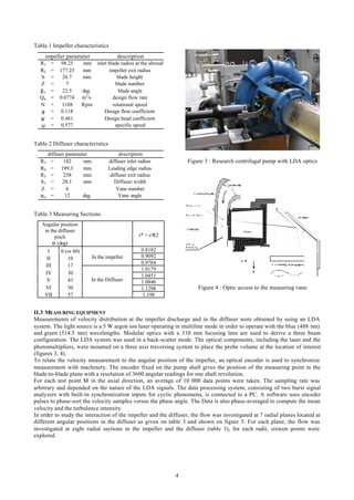
Figure 8 : Turbulence intensity at impeller exit r/R2=0.978, plane I, design flow
0 10 20 30 40 50
Angular position (deg)
0
20
40
60
80
100
Tu(%)
Tu (Cr)
Tu (Cu)
r/R2 = 0.978
z/b = 0.17
Plane II
0 10 20 30 40 50
Angular position (deg)
0
20
40
60
80
100
Tu(%)
Tu (Cr)
Tu (Cu)
r/R2 = 0.978
z/b = 0.5
Plane II
0 10 20 30 40 50
Angular position (deg)
0
20
40
60
80
100
Tu(%)
Tu (Cr)
Tu (Cu)
r/R2 = 0.978
z/b = 0.85
Plane II
Figure 9 : Turbulence intensity at impeller exit r/R2=0.978, plane II, design flow
[ ]
n
CC
Crms
ni
i
2
12'
θθ
θ
−
==
=
=
Σ
The turbulence level can be calculated for every angle using the following definition :
[ ]
[ ]
100
1
1
100
2
2
1
1
×
−
=×= =
=
=
=
Σ
Σ
θ
θθ
θ
C
n
CC
n
C
rms
Tu ni
i
ni
i
Sample plots of the turbulence intensity distribution in the interblade passage, just upstream of the impeller discharge,
are shown on figure 8 and 9. On figure 8 the evolution of turbulence is given for plane I at the shroud (z/b=0.17),
passage midheight (z/b=0.5) and at the hub (z/b=0.85). On these figure, the turbulence is given as a function of the
angular position for witch the suction side of the passage corresponding to zero, while the pressure side corresponds to
51 deg.
At the hub region, the turbulence intensity is low and its distribution is uniform in the impeller passages, it hardly
exceeds 15 percent. As reported by Cattanei et al. (1998), the high turbulence intensities up to 40 percent observed at
the suction side/shroud corner and the passage center are due to the presence of the wake as observed if figure 9. This
region of the passage is occupied by a low relative velocity flow having important velocity gradients. The hub region
where the jet is prevailing the turbulence intensity is much lower. This distribution of the turbulence intensity remains
almost identical in all the measuring planes except at plane II where a different turbulence distribution was observed
(figure 9). In this plane, the fluctuations are higher and the turbulence level reaches 80 percent at the suction side/shroud
corner. It is the same case at the passage midheight where it approaches 60 percent. The hub region (z/b = 0.85) is also
affected and is characterized by a distinct rise of flow unsteadiness at the passage midspan.
7. 8
C
17.8367
15.5102
12.4082
9.30612
6.97959
4.65306
2.32653
0
T 1
R 1
R 2
S 2
S 1
I
I I
I II
IV
V
VI
VII
C
17.8367
15.5102
12.4082
9.30612
6.97959
4.65306
2.32653
0
T 11
R 1
R 2
S 2
S 1
I
I I
I II
IV
V
VI
VII
C
17.8367
15.5102
12.4082
9.30612
6.97959
4.65306
2.32653
0
T 31
R 1
R 2
S 2
S 1
I
I I
I II
IV
V
VI
VII
C
17.8367
15.5102
12.4082
9.30612
6.97959
4.65306
2.32653
0
T 41
R 1
R 2
S 2
S 1
I
I I
I II
IV
V
VI
VII
Figure 10 : Time resolved flow field frames
III.5 ABSOLUTE FLOW DISTRIBUTION
On figure 10, the results are presented as constant absolute velocity contours. The frames represent, at different instants
T1, T11, T31 and T41, the impeller blades R1 and R2 rotating from left to right in front of the diffuser vanes S1 and S2.
The time period between the passage of two successive impeller blades, in front of a diffuser vane, corresponds to 51
instants.
The Frames show a very deep evolution of the flow structure as it approaches the impeller discharge. At the inner
sections of the impeller, a large part of the channel is occupied by the parallel constant velocity contours corresponding,
to the potential flow distribution with a negative gradient from the suction side to the pressure side. This inviscid
behavior of the flow is only altered in a small section of the channel confined to the suction side/shroud surface. In this
region where the flow has a high absolute velocity and an important velocity gradient is registered. As the fluid is
achieved to the impeller discharge, the core of the high velocity fluid moves from the suction side/shroud corner to the
suction side of the impeller. The flow is therefor organized in a jet-wake structure as reported by previous research
works on centrifugal machines. Even though there is a slight alteration of the velocity, the flow patterns in the impeller
remain almost unchanged when the distance between the measurement section and the leading edge of the diffuser is
modified. The frontier between the rotor and the stator seems to be not easily crossed. At the design point, The flow
within the impeller is hardly affected by the presence of the vaned diffuser as noticed by Toussaint (1998).
At the diffuser inlet, the mixing of the jet-wake structure depends on the proximity of the diffuser vanes. At the radial
planes III and IV, the wake core moves towards the channel mid height. In plane IV, the flow is almost uniform when it
reaches r/R2=1.084, this indicates that the mixing process of the complex periodic flow coming out of the impeller has
finished. In the following planes, the jet-wake is still present. A more important radial component of the velocity, as
seen in figure 7, seems to delay the mixing process. When approaching the diffuser throat (planes VI and I), an
8. 9
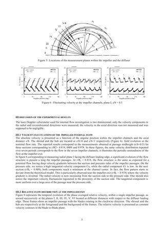
important velocity is registered on the pressure side of the vanes, the flow ruches to enter in the diffuser channels. In the
suction side, a flow slow down prevents the flow structure leaving the impeller to diffuse in the radial direction.
CONCLUSION
This detailed investigation of the internal flow within a centrifugal pump, at its design point, has permitted to study the
effect of a vaned diffuser on the flow inside the impeller. From the actual results, we can conclude that the impeller-
diffuser interaction is limited to the impeller exit and it does not have any upstream influence on the flow. The frontier
between the rotor and the stator seems to be not easily crossed. The mixing process of the flow at the impeller discharge
is affected by the presence of the diffuser vanes. The first half of the diffuser pitch is characterized by an early mixing
of the flow. Whereas, in the second half, the flow entering the diffuser channel is still presenting its periodicity due to
the impeller. This results indicates, therefore, that the diffuser performances may be affected by the complex flow
coming out the impeller. Further investigations in the diffuser and at different operating conditions are projected to
better understand the rotor-stator interaction.
REFERENCES
[1] N. Arndt, A. J. Acosta, C. E. Brennen, T. K. Caughey, Rotor-stator interaction in a diffuser pump, Journal of
Turbomachinery, 1989, Vol. 111, N° 3, p. 213-221.
[2] N. Arndt, A. J. Acosta, C. E. Brennen, T. K. Caughey, Experimental investigation of rotor-stator interaction in a
centrifugal pump with several vaned diffusers, Journal of Turbomachinery, 1990, Vol. 112, N° 1, p. 98-108.
[3] A. Cattanei, D. Ottolio, M. Ubaldi, P. Zunino. "Unsteady Boundary Layers on the Blades of a Centrifugal Stage
Due to Rotor Blade Wake Interaction", 9th
Intl. Symp. On Appl. Of Laser techniques to Fluid Mechanics, July 13-
16, 1998 Lisbon, Portugal.
[4] D. Eckardt, Instantaneous Measurements in the Jet-Wake Discharge Flow of a Centrifugal Compressor Impeller,
Journal of Engineering for Power, July 1975, p. 337-345.
[5] D. Eckardt, Detailed Flow Investigations within a High-Speed Centrifugal Compressor Impeller, Journal of Fluids
Engineering, September 1976, p. 390-401.
[6] M. El Hajem, R. Morel, J.Y. Champagne, F. Spettel. "Centrifugal Impeller Flow Investigation", 1998 ASME Fluids
Engineering Division Summer Meeting, June 21–25, 1998, Washington, DC.
[7] M. El Hajem, R. Morel, J.Y. Champagne, F. Spettel. " Detailed Measurements of the Internal Flow of a Backswept
Centrifugal Impeller", 9th
Intl. Symp. On Appl. Of Laser techniques to Fluid Mechanics, July 13-16, 1998 Lisbon,
Portugal.
[8] M. Inoue, N. A. Cumpsty, Experimental Study of Centrifugal Impeller Discharge Flow in Vaneless and Vaned
Diffusers, Journal of engineering for gas turbines and power, 1984, Vol. 106, N° 2, p. 455-467.
[9] J. P. Johnston, S. A. Eide, Turbulent Boundary Layers on Centrifugal Compressors Blades: Prediction of the
Effects of Surface Curvature and Rotation, Journal of Fluids Engineering, September 1976, p. 374-381.
[10] M. W. Johnson, Secondary Flow in Rotating Bends. Journal of Engineering for Power, October 1978, Vol. 100, p.
553-560.
[11] H. Krain, Swirling Impeller Flow, Journal of Turbomachinery, January 1988, Vol. 110, p. 122-128.
[12] K. H. Rohne, M. Banzhaf, Investigation of the Flow at the exit of Unshrouded Centrifugal Impeller and
Comparison With the classical Jet-Wake Theory, Journal of Turbomachinery, October 1991, Vol. 113, p. 654-659.
[13] C. H. Liu, C. Vafidis, J. H., Whitelaw, Flow characteristics of a centrifugal pump, Journal of fluids Engineering,
1994, Vol. 116, N° 2, p. 303-309.
[14] S. M. Miner, R. J. Beaudoin, R. D. Flack, Laser velocimetery measurements in a centrifugal flow pump, Journal of
Turbomachinery, 1989, Vol. 111, N°3, p. 205-212.
[15] M. Th.Sideris , R. A. Van DEN braembussche, Influence of a circumferential exit pressure distortion on the flow in
an impeller and diffuser, Journal of Turbomachinery, 1987, Vol. 109, N° 1, p. 48-54.
[16] M. Toussaint , F. Hureau, J. F. Lapray, Influence des diffuseurs aubés sur le fonctionnement des pompes
centrifuges, La Houille Blanche n° 3/4, 1998, p. 38-44.
[17] M. Ubaldi, P. Zunino, A. Cattanei, Relative Flow and Turbulence Measurements Downstream of a Backward
Centrifugal Impeller, Journal of Turbomachinery, July 1993, Vol. 115, p. 543-551.