SlideShare a Scribd company logo
1 of 8
Download to read offline
50th AIAA Aerospace Sciences Meeting including the New Horizons Forum and Aerospace Exposition                                 AIAA 2012-0147
09 - 12 January 2012, Nashville, Tennessee


                    SOLSTICE: Standalone-electric Optimized Lifting System,
                          Transitional Internal Combustion Engine

                                   M. Cui, T. Drake, A. Kreuter, G. Kutil, B. Miller, C. Packard, M. Rahimpour and G. Soin 1
                                     Aerospace Engineering Sciences, University of Colorado, Boulder, Colorado, 80309


                                This paper will focus on the innovative design architecture of the SOLSTICE hybrid
                            aircraft propulsion system. The goal of this project is to design, manufacture, integrate and
                            test a hybrid combustion/electric propulsion system to be integrated with a blended wing-
                            body aircraft currently being designed by Hyperion, an international team led by graduate
                            students at the University of Colorado. The concepts of operation will be discussed as well in
                            order to elaborate on the development of a transitionable power control system, allowing the
                            coaxial combustion engine and electric motor to operate in tandem or separately. Based on
                            requirements provided by the Hyperion graduate team, the propulsion system is designed in
                            part around power and thermal requirements. Analytical modeling of the engine system
                            with respect to these facets has been performed and multiple testing scenarios will be run in
                            order to validate these models. Verification of the hybrid propulsion system will be
                            performed on the ground, setting flight testing on the Hyperion aircraft as a stretch goal.
                            The SOLSTICE team plans to provide its customer, Dr. Jean Koster, with design
                            recommendations for future hybrid aircraft propulsion endeavors, moving aircraft
                            propulsion into a greener, fuel economy-friendlier realm.


                                                                                  Nomenclature
                DAQ            =    data acquisition system
                EM             =    electric motor
                ESC            =    electronic speed controller
                HPS            =    hybrid propulsion system
                ICE            =    internal combustion engine
                RPM            =    revolutions per minute

                                                                               I. Introduction

                T    HE Standalone-electric Optimized Lifting System, Transitional Internal Combustion Engine, or SOLSTICE,
                     represents a turning point in how aircraft
                will be flown in the future. The goal of this
                project is to design, manufacture, integrate and
                test a hybrid combustion/electric propulsion
                system specifically for small aircraft. Currently,
                hybrid propulsion systems for aircraft are nearly
                nonexistent. However, the possibilities for their
                uses in multiple fields of aviation would allow
                for many performance benefits. An aircraft that
                is able to utilize a standard combustion system
                during normal flight and then transition to a
                much quieter electric motor during landing
                would greatly alleviate noise pollution, rampant
                at and around today’s airports. A transitional
                hybrid engine would also allow for greater fuel    Figure 1. Hyperion Blended Wing-Body Aircraft Design.

                1
                 Undergraduate Students, Aerospace Engineering Sciences Dept., Engineering Center 1111 Engineering Dr, AIAA
                Student Members
                                                                      1
                                              American Institute of Aeronautics and Astronautics

Copyright © 2012 by the American Institute of Aeronautics and Astronautics, Inc. All rights reserved.
efficiency (similar to a hybrid car) by decreasing fuel expenditure, allowing the combustion engine to operate more
efficiently while the electric motor provides any remaining power necessary for flight.
    The SOLSTICE HPS is one facet of a larger program known as Hyperion. The Hyperion team is an international
amalgamation, comprised of students from the University of Stuttgart in Germany, from the University of Sydney in
Australia, and from the University of Colorado, represented by both undergraduate and graduate teams. Under the
leadership of the CU graduate team, Hyperion is designing a model blended wing-body aircraft, seen in Fig. 1, with
the intent of developing a cleaner, greener and quieter aircraft system. The SOLSTICE undergraduate team is
responsible for the propulsion system of this new aircraft concept.
    The Hyperion team plans to fly the modeled aircraft in multiple flight modes, including cruise, quiet and dash,
through the utilization of the SOLSTICE hybrid engine design. To achieve these different operational modes, the
SOLSTICE engine controls two motors within the hybrid system either individually or in tandem: dash mode
utilizes both the internal combustion engine and the electric motor while quiet mode uses the electric motor only.
Cruise uses the combustion engine alone. SOLSTICE is designing the control system to operate these flight modes
along with the physical HPS.


                                          II. System Configuration
    The SOLSTICE hybrid propulsion system makes use of two separate engines, one electric motor (EM) and one
internal combustion engine (ICE) to drive the propeller. A patent-pending gearbox converts the input torques of
these two engines into one output torque, turning the propeller shaft. Power sources for the EM and ICE consist of
batteries and fuel, respectively. By utilizing the EM and ICE either concurrently or independently the various flight
modes can be achieved such as EM only for quiet operation or EM and ICE concurrently for maximum power. The
entire system, excluding power
supplies, is placed on a single
base plate to allow for ease of
integration      and     structural
rigidity. The overall system is
constrained in mass and volume
as it is necessary for the HPS to
fit inside the Hyperion aircraft.
During the fall semester design
phase, multiple analytical models
were       produced       (thermal,
structural stress and strain, and
power) in order to ensure that the
system      will    provide     the
necessary power to successfully
fly the Hyperion aircraft. Figure
2 illustrates the propulsion                 Figure 2. SOLSTICE Hybrid Propulsion System Configuration.
system configuration to be
manufactured in the spring semester, 2011.
    This configuration was designed iteratively over the course of the fall semester utilizing a systems engineering
approach, working from broad to specific requirements. Initially the team worked with advisors and clients to
develop a preliminary goal and set of objectives. As is common practice, top level requirements were devised based
on these objectives and on certain parameters such as the overall aircraft mass restrictions. During the Preliminary
Design phase, these requirements were broken down to a subsystem level where enough detail was defined in order
to narrow down selection of components. Trade studies were performed and the design continued with those
selected. The overall system architecture was continually observed, allowing for a constant systems engineering
perspective. The results of these studies and their impact on the design were presented to a panel of aerospace
engineering faculty in a Preliminary Design Review (PDR). In the following Critical Design phase, parts were
selected and prototyping of major risks in order to find mitigating solutions was performed. During the Critical
Design Review (CDR) modifications to the preliminary system architecture were presented by the team as a part of
the complete system, its components and the analysis behind their design/selection.


                                                         2
                                 American Institute of Aeronautics and Astronautics
This educational process goes hand-in-hand with aerospace industry practices. Project definition is the first and
foremost step to the design process even with the existence of a multitude of unknowns at the time. This process-
and the process to follow in the spring semester- has invaluably prepared the SOLSTICE team for any future
engineering endeavors.


                                            III. System Modeling
   Modeling physical and conceptual systems is a necessary process within engineering. The ability to predict
performance increases the probability of successfully completing a project. Prediction through modeling can
produce a more thorough understanding of a system’s characteristics and interdependencies. In most situations,
modeling, combined with testing, generates this understanding earlier and more efficiently than testing alone.
Increasing efficiency not only allows a project to be completed in a shorter period of time, but also decreases the
amount of funds necessary for project completion.

A. Power Modeling
    SOLSTICE’s main requirement from Hyperion, derived from the desired multiple flight modes, is that either
the electric motor or the internal combustion engine must supply the aircraft with 2 horsepower. During the design
                                                                                     phase of the project, a simple, yet
                                                                                     effective, power model was
                                                                                     developed to ensure SOLSTICE’s
                                                                                     HPS could meet Hyperion’s
                                                                                     requirement. The model takes
                                                                                     into account all major functional
                                                                                     inefficiencies to predict the
                                                                                     propulsion      system’s    power
                Figure 3. Power Model Component Efficiency.                          output.     The major functional
                                                                                     inefficiencies within the system
include friction losses from gearing and losses within the electric motor linked to converting electrical power to
mechanical power. Figure 3 represents the structure of the model visually. It is predicted through analysis that the
gearing is 75% efficient with a confidence of
70%. The confidence is based on the possible
range of coefficients of friction for meshing
gears. The electric motor was assigned an
efficiency of 80% based on manufacturer
specifications and lessons learned from
previous experience.
    One of the novelties of the SOLSTICE           Figure 4. Aircraft Flight Modes in Concept of Operations.
engine is the capability of running on
different modes. This ultimately allows the aircraft to also fly at different flight modes and can be used to optimize
and limit fuel consumption. An example of how the variable flight operations can be utilized in an aircraft is
shown in Fig. 4.
    Figure 4 shows how an aircraft can take advantage of the engine to achieve periods of maximum velocity,
minimal fuel consumption, and regular flight operations. This concept was the foundation of the project: to
conceive and build an engine capable of performing each of these flight modes. Each flight mode has a power
                                                                                            output necessary to fly the
               Table 1. Required Propeller Output for Flight Modes
                                                                                            aircraft as desired. The
       Flight Mode         Power (W)        Velocity (m/s)       Ideal Prop RPM
                                                                                            power output needed for
          Takeoff             1500              >7.6                    1795.3
                                                                                            each flight      mode is
          Cruise               750               24.3                   5740.2
                                                                                            summarized in Table 1.
           Quiet               410               13.6                   3212.6              The output power is the
           Dash               1500               32.4                   7653.5              power required from the
         Landing               460                9.9                   2338.6              propeller.


                                                         3
                                 American Institute of Aeronautics and Astronautics
B. Thermal Modeling
   Of major concern in integration of the hybrid propulsion system with the aircraft is the generation of heat by the
                                           system. Because the propulsion system is located within the fuselage of
                                           the aircraft, the heat generated by the system will heat the surrounding
                                           aircraft structure and skin. The skin of the aircraft is fabricated from a
                                           fiberglass-epoxy material that must remain below 60oC in order to avoid
                                           material softening. To determine the thermodynamic characteristics of
                                           the system, two assumptions were made. The first assumption is that all
                                           power lost from inefficiencies in the system is fully converted to heat.
                                           The second assumption is no force convection over the system, only free
                                           convection. These two assumptions provide a worst case scenario of the
                                           propulsion system during operation. Through lumped analysis, it was
                                           determined that the system would produce 700W of heat via the three
                                           mechanisms of heat transfer. The heat transfer present within the engine
                                           cavity is shown in Fig. 5.
                                               In order to mitigate the risk of weakening the fiberglass epoxy’s
                                           integrity, forced convection over the system will be required. This shall
                                           be accomplished by implementing a duct into the nose of the aircraft.
                                           Further analysis of the system showed that a relation between the
                                           necessary forced convection properties, such as the convection
    Figure 5. Heat Transfer Model.         coefficient and the flow speed, could be determined as a function of the
                                           total heat transfer. The relation is shown in Fig. 6 which gives the
                                           convection coefficient and flow speed required to keep fiberglass skin
under 60oC.
   The model proved that as the heat transfer decreases, the required airflow over the system decreases. It was
determined that a heat transfer of 700W is the worst case scenario thus the design team is confident that passive air
cooling from the Hyperion aircraft will be sufficient for operational temperature.

  150                                                                                                           Forced Convection Model
                                                                                          17
                 Convection Coefficient, h [W/m 2 K]
                 Airflow Speed, V [m/s]                                                   16


                                                                                          15
  100
                                                                   Mass Flow Rate (g/s)


                                                                                          14


                                                                                          13


   50                                                                                     12


                                                                                          11


                                                                                          10

    0
        0     100    200    300     400     500        600   700                          9
                                                                                          270      275         280        285         290          295   300
                        Heat Transfer Q [W]                                                              Anticipated Ambient Air Temperature (K)
            Figure 6. Forced Convection Required.                                               Figure 7. Necessary System Cooling.


    Further modeling has provided a mass flow rate necessary for operation, based on expected atmospheric
conditions and the required interior temperature limit of 60 oC. The model predicts a mass flow rate range of 9.5 to
16.5 g/s. Currently a mass flow rate equal to or greater than 34 g/s is expected to account for the worse case
scenario and a factor of safety of 2. Figure 7 displays the mass flow rate’s dependence on the anticipated
freestream temperature range. The model assumes steady state flow, the air is perfectly mixed within the system’s
cavity, and heat transfer is limited to convection within the cavity and conduction through the aircraft’s skin.


                                                              4
                                      American Institute of Aeronautics and Astronautics
IV. System Verification
   The next step following system modeling is performing tests with real hardware and software. The data
obtained from system and subsystem tests can then be analyzed and used to verify the different system models. In
order for these tests to represent the models accurately, the hardware including electronics and software used
during the tests should be the actual flight hardware and not prototypes. System verification tests are the final step
before the overall system design can be validated and approved for flight. As such, it is essential that these tests be
performed following detailed laid out procedures as well as be repeated multiple times to obtain accurate data.

A. Power Testing
   One of the primary requirements that the SOLSTICE HPS has to supply a minimum of 2 horsepower from its
                                           Electric Motor and Internal Combustion engine. These power
                                           requirements are essential for the Hyperion aircraft to achieve flight
                                           and also to verify their Concept of Operations. The SOLSTICE team
                                           performed tests on its HPS and used the data to verify the power
                                           output from the system. The primary apparatus used for these tests was
                                           a reaction force dynamometer which utilizes a force transducer to
                                           measure the reaction torque from the HPS. This is coupled with a
                                           voltage expander and an RPM sensor which together measure the input
                                           power to the system. The data obtained from these two sensors are
                                           then analyzed and compared in order to obtain the efficiency curves
                                           for the different components of the HPS. The setup for this apparatus
                                           can be seen in Fig. 8.
                                                                                    100


                                                                                    95
                                                       SOLSTICE EM Efficiency [%]


    Figure 8. Dynamometer with EM                       90

                Attached.
    Figures 9, 10 and 11 represent the efficiency       85

and power curves for the most critical
components of SOLSTICE's HPS namely the                 80
Electric Motor and the propeller. Using the
dynamometer, SOLSTICE has been able to                  75
quantify the efficiency of both these                                                              EM Efficiency
components.                                                                                        Polyfit
                                                        70
    Figure 9 shows the efficiency curve for the          4000   4500    5000    5500     6000 6500   7000       7500
SOLSTICE Electric Motor plotted against its                                          RPM

RPM. The test was performed between a range                      Figure 9. EM Efficiency vs. RPM.
of 5 to 20 Amps at intervals of 5 Amps in order
to replicate the desired flight conditions for the EM. The design specifications for the EM provided by the
manufacturer rate the efficiency to be approximately 80%. From the EM dynamometer test, this specification was
verified and the efficiency of the motor was approximated to be 85% under the desired flight operation conditions.
    In order to verify that the SOLSTICE Electric Motor has the required power to satisfy the given power
requirement, another dynamometer test was performed to quantify the power output of the motor. This was again
plotted against RPM and is shown in Fig. 10. Due to structural limitations of the SOLSTICE Dynamometer, the test
could not be performed at the optimum range of input current for the EM. However, the test performed provided the
relation through which the SOLSTICE team could then extrapolate the power output at higher current values.
Through these analysis, it was determined that at an RPM of 8750, the SOLSTICE EM will output 1500 Watts of
power which includes the 85% EM efficiency determined from the previous test. This power output is equivalent to
the 2 horsepower requirement. Hence, with the help of this test and its analysis, SOLSTICE has been able to
successfully verify its power requirements.


                                                         5
                                 American Institute of Aeronautics and Astronautics
800
                                                                                                                              Although, the power requirements
                                                                                                                          give to SOLSTICE by the Hyperion
                              700                                                                                         team accounted for a propeller
                                                                                                                          efficiency of 50%, SOLSTICE did
   SOLSTICE EM Output Power


                              600                                                                                         another dynamometer test to verify the
                                                                                                                          efficiency of the actual flight propeller.
                              500                                                                                         This was done in order to be thorough
                                                                                                                          and obtain accurate power curves for
                              400                                                                                         the HPS.
                                                                                                                              Figure 11 shows the efficiency
                              300                                                                                         curve of the flight propeller plotted
                                                                                                                          against RPM along with a least squares
                              200                                                                                         regression curve denoted as "Polyfit".
                                                                                                                          The      profile    changes       because
                              100
                                                                                                                          SOLSTICE is using a single speed
                                4000   4500   5000   5500         6000   6500                     7000     7500           propeller which is designed to have a
                                                            RPM
   Figure 10. EM Output Power in Watts(Including EM Efficiency)                                                           maximum efficiency at a single point.
                                   vs. RPM.
The approximate propeller efficiency               70
determined from this test is 55% to 65%
which is higher than what the Hyperion             60
requirements accounted for. Thus, the analysis
for this test further strengthens the verification 50
of the SOLSTICE power requirements.
                                                                                Efficiency [%]


                                                                                                 40


                                                                                                 30


                                                                                                 20


                                                                                                 10
                                                                                                            Propeller Efficiency
                                                                                                            Polyfit
                                                                                                 0
                                                                                                 1500    2000     2500   3000      3500  4000   4500   5000   5500   6000
                                                                                                                                      RPM
                                                                                                           Figure 11. Propeller Efficiency vs. RPM.

B. Thermal Testing
   To verify the thermodynamics and heat transfer of the hybrid propulsion system, tests are to be conducted to
verify the requirements set forth by the structural integrity of the aircraft. The tests include measuring the thermal
                                                              output from each component in the system. The major
                                                              components that must be considered from a
                                                              thermodynamic perspective are the internal combustion
                                                              engine, electric motor, electronic speed controller,
                                                              gearbox, and electronic circuits. Each component has
                                                              inefficiencies where power losses generate heat. To
                                                              experimentally determine the heat transfer of the
                                                              system components, a test box is utilized that has the
                                                              same geometry as the engine cavity within the aircraft.
                                                              The test box also utilizes a polycarbonate material that
                                                              has similar thermal properties as the fiberglass skin of
                                                              the aircraft. A representation of the test box is shown in
                                                              Fig. 12. In addition, the location of the temperature
           Figure 12. Thermal Test Bed Setup.                 sensors placed throughout the box to measure the

                                                                              6
                                                      American Institute of Aeronautics and Astronautics
change in ambient temperature is shown. For the tests, seven LM 34 temperature sensors are to be used that
measure the ambient temperature in Fahrenheit. Using the Fahrenheit sensors allows for a better signal to noise
ratio than that of the Celsius LM35 sensors.
    The first thermal test performed gave insight into how hot the engine cavity would get during the taxi portion of
the flight. To simulate this, the internal combustion engine is to run on idle with the engine completely sealed
within the box. During taxi, the propeller wash is negligible and is considered zero to test a worst case scenario.
The test results, shown in Fig. 13, proved that over a span of 17 minutes, the temperature throughout the engine
cavity does increase with the engine in idle. The maximum temperature measured during the 17 minute idle was
40oC located directly above the idling engine.
This is still below the maximum 60oC required be          45
                                                                    Sensor 1
the aircraft structure. When the aircraft takes to                  Sensor 2
                                                          40
the air, the propeller will generate prop wash that                 Sensor 3
will flow over the system and provide passive air                   Sensor 4
                                                          35        Sensor 5
cooling.


                                                       Ambient Temperature [C]
                                                                    Sensor 6
    Testing of the electric motor and electronic                    Sensor 7
                                                          30
speed controller are still to be performed however
from preliminary dynamometer testing, the team
                                                          25
is confident that these component will not
generate any substantial heat and any forced
                                                          20
convection will be sufficient for the required
cooling. In addition, the gearbox will use
lubrication that has the appropriate viscosity that       15

will ensure minimal heat generation. Finally, a
full system test is to be performed several times         10
                                                             0   2     4     6   8     10     12 14  16   18    20
that will follow the aircraft mission and concept                                  Time [min]

of operations. This test will be performed a             Figure 13. ICE Idle Results, No Forced Convection.
multitude of times to ensure reliability in the
thermodynamics and heat transfer of the hybrid propulsion system to the aircraft.

                                          V. System Applications
    The advantage of the SOLSTICE system comes from the ability to change between fundamentally different
types of engines. The ICE has the advantage of burning fuel, reducing the overall weight of the aircraft over time.
The EM has the advantages of quiet operation relative to the ICE and it has the ability to run at higher altitudes.
    A typical use of the SOLSTICE engine will cycle the ICE and EM based on the flight regimes. The flight
regimes include a dash mode which utilizes the power of both engines to reach a maximum speed for the aircraft.
This engine mode also has the ability to provide significant thrust for takeoff through running the two engines
together. This allows the selected engines to be smaller and tailored more towards the maximum thrust needed in
cruise conditions. The next flight regime utilizes the EM only. This flight regime can be considered a quiet mode
and can be used in urban areas where noise levels are an issue. This mode can be used for unobtrusive surveillance
of targets as well. It has also been proposed that this flight regime be used as a high altitude mode, allowing the
aircraft to fly at higher altitudes than those at which an ICE is capable of operating. The ICE-only flight regime can
be thought of as a general purpose mode. By burning the majority of the stored fuel during takeoff and climb the
thrust needed in cruise would be minimized for a higher percent of the mission duration. In the future the ICE may
be made to use a bio-fuel such as biodiesel to decrease its environmental impact. This could potentially lower the
fuel cost of operations which would be further offset by the use of the electric motor.
    The basic design of the SOLSTICE engine is not limited only to a propulsion system. A further application
would be as a portable generator for remote operations such as Antarctica or disaster relief. This would involve
replacing the EM with a generator and the propeller with a turbine blade optimized for power generation. The
system provides near-limitless power from the wind. This is augmented with the ICE as a traditional gas generator.
By relying on the gas generator only when there is no wind the operation would need to carry less fuel for their
power needs. In windy places the ICE could be seen as an emergency option. The combination of the two sources
would reduce the total weight of the system and make it more portable than the two systems individually.


                                                         7
                                 American Institute of Aeronautics and Astronautics
VI. Conclusion
    Although the application hybrid technology in aircraft has only recently become a topic of serious interest in the
aerospace community, it is a necessary technology in ensuring that the aircraft of the future are both fuel efficient
and environmentally friendly. The SOLSTICE project provides further development in the field of hybrid aircraft
propulsion through testing and modeling to verify the validity of such a system in aircraft. Current applications of
the SOLSTICE project are limited to UAV markets due to current battery technologies. However, with an ever
increasing interest in both UAV application and lessening carbon foot-prints, the SOLSTICE system is relevant in
today’s aircraft industry. The current state of testing verifies that the EM meets the power requirements and that the
propeller exceeds expected efficiency. Through the design process of the HPS, many valuable lessons have been
learned including the importance of communication within the team and with the customer. Since the project
represents a global effort between students from various countries it is necessary that communication is clear and
concise to ensure that any problems that may arise are mitigated diligently and efficiently. By developing a system
with the potential to rely less on fossil fuels for energy this project represents a global interest in ensuring that the
future of aircraft propulsion is cleaner and safer.

                                                 Acknowledgments
    The authors thank Dr. Jean Koster and Dr. Donna Gerren for their continued advice on this project. The team
also appreciates the strong support and guidance received from Cody Humbargar and the entire Hyperion team
(Scott Balaban, Derek Nasso, Andrew Brewer, Julie Price, Chelsea Goodman, Eric Serani, Derek Hillery, Alec
Velazco, Mark Johnson, Richard Zhao, and Tom Wiley). We also thank the international partner teams from the
University of Stuttgart in Germany and from the University of Sydney in Australia who helped make this project a
fascinating and unique learning experience. Funding for this project is provided in part by The Boeing Company,
eSpace Inc., and NASA under grant NNX09AF65G.


                                                         8
                                 American Institute of Aeronautics and Astronautics

More Related Content

What's hot

International Conference More Electric Aircraft - Advancements in electric po...
International Conference More Electric Aircraft - Advancements in electric po...International Conference More Electric Aircraft - Advancements in electric po...
International Conference More Electric Aircraft - Advancements in electric po...Torben Haagh
 
IRJET - An Experimental Investigation and Reduction of NOX and HC Emission in...
IRJET - An Experimental Investigation and Reduction of NOX and HC Emission in...IRJET - An Experimental Investigation and Reduction of NOX and HC Emission in...
IRJET - An Experimental Investigation and Reduction of NOX and HC Emission in...IRJET Journal
 
AirVenture 2009 Electric Propulsion Presentation
AirVenture 2009 Electric Propulsion PresentationAirVenture 2009 Electric Propulsion Presentation
AirVenture 2009 Electric Propulsion PresentationBye Aerospace
 
Study and Analysis of Nonlinear Constrained Components A Study of Plug-in Hyb...
Study and Analysis of Nonlinear Constrained Components A Study of Plug-in Hyb...Study and Analysis of Nonlinear Constrained Components A Study of Plug-in Hyb...
Study and Analysis of Nonlinear Constrained Components A Study of Plug-in Hyb...ijtsrd
 
Neil Garrigan: Electric Drive Technology Considerations for Aircraft Propulsion
Neil Garrigan: Electric Drive Technology Considerations for Aircraft Propulsion Neil Garrigan: Electric Drive Technology Considerations for Aircraft Propulsion
Neil Garrigan: Electric Drive Technology Considerations for Aircraft Propulsion EnergyTech2015
 
Electric and Hybrid vehicles
Electric and Hybrid vehiclesElectric and Hybrid vehicles
Electric and Hybrid vehiclesK C KARTHIK
 

What's hot (8)

International Conference More Electric Aircraft - Advancements in electric po...
International Conference More Electric Aircraft - Advancements in electric po...International Conference More Electric Aircraft - Advancements in electric po...
International Conference More Electric Aircraft - Advancements in electric po...
 
IRJET - An Experimental Investigation and Reduction of NOX and HC Emission in...
IRJET - An Experimental Investigation and Reduction of NOX and HC Emission in...IRJET - An Experimental Investigation and Reduction of NOX and HC Emission in...
IRJET - An Experimental Investigation and Reduction of NOX and HC Emission in...
 
AirVenture 2009 Electric Propulsion Presentation
AirVenture 2009 Electric Propulsion PresentationAirVenture 2009 Electric Propulsion Presentation
AirVenture 2009 Electric Propulsion Presentation
 
Study and Analysis of Nonlinear Constrained Components A Study of Plug-in Hyb...
Study and Analysis of Nonlinear Constrained Components A Study of Plug-in Hyb...Study and Analysis of Nonlinear Constrained Components A Study of Plug-in Hyb...
Study and Analysis of Nonlinear Constrained Components A Study of Plug-in Hyb...
 
Neil Garrigan: Electric Drive Technology Considerations for Aircraft Propulsion
Neil Garrigan: Electric Drive Technology Considerations for Aircraft Propulsion Neil Garrigan: Electric Drive Technology Considerations for Aircraft Propulsion
Neil Garrigan: Electric Drive Technology Considerations for Aircraft Propulsion
 
Abstract DEP
Abstract DEPAbstract DEP
Abstract DEP
 
Electric and Hybrid vehicles
Electric and Hybrid vehiclesElectric and Hybrid vehicles
Electric and Hybrid vehicles
 
C012261114
C012261114C012261114
C012261114
 

Viewers also liked

Hyperion Solstice Presentations
Hyperion Solstice PresentationsHyperion Solstice Presentations
Hyperion Solstice PresentationsJean Koster
 
North America Aerospace Project
North America Aerospace ProjectNorth America Aerospace Project
North America Aerospace ProjectJean Koster
 
Hyperion videos on youtube
Hyperion videos on youtubeHyperion videos on youtube
Hyperion videos on youtubeJean Koster
 
Aes Senior Design Brochure
Aes Senior Design BrochureAes Senior Design Brochure
Aes Senior Design BrochureJean Koster
 
Aiaa 2012 629 429 Soposades
Aiaa 2012 629 429 SoposadesAiaa 2012 629 429 Soposades
Aiaa 2012 629 429 SoposadesJean Koster
 
AIAA 2012 1223 472 Hyperion Int Collab
AIAA 2012 1223 472 Hyperion Int CollabAIAA 2012 1223 472 Hyperion Int Collab
AIAA 2012 1223 472 Hyperion Int CollabJean Koster
 
AIAA 2012 878 312 Hyperion Green Aircraft
AIAA 2012 878 312 Hyperion Green AircraftAIAA 2012 878 312 Hyperion Green Aircraft
AIAA 2012 878 312 Hyperion Green AircraftJean Koster
 

Viewers also liked (8)

Hyperion Solstice Presentations
Hyperion Solstice PresentationsHyperion Solstice Presentations
Hyperion Solstice Presentations
 
North America Aerospace Project
North America Aerospace ProjectNorth America Aerospace Project
North America Aerospace Project
 
Hyperion videos on youtube
Hyperion videos on youtubeHyperion videos on youtube
Hyperion videos on youtube
 
Aes Senior Design Brochure
Aes Senior Design BrochureAes Senior Design Brochure
Aes Senior Design Brochure
 
Aiaa 2012 629 429 Soposades
Aiaa 2012 629 429 SoposadesAiaa 2012 629 429 Soposades
Aiaa 2012 629 429 Soposades
 
AIAA 2012 1223 472 Hyperion Int Collab
AIAA 2012 1223 472 Hyperion Int CollabAIAA 2012 1223 472 Hyperion Int Collab
AIAA 2012 1223 472 Hyperion Int Collab
 
AIAA 2012 878 312 Hyperion Green Aircraft
AIAA 2012 878 312 Hyperion Green AircraftAIAA 2012 878 312 Hyperion Green Aircraft
AIAA 2012 878 312 Hyperion Green Aircraft
 
FRED's, Inc.
FRED's, Inc.FRED's, Inc.
FRED's, Inc.
 

Similar to AIAA 2012 147 188 Solstice

LASER AIAA PAPER (1)
LASER AIAA PAPER (1)LASER AIAA PAPER (1)
LASER AIAA PAPER (1)Austin Gerber
 
Feasibility Study and Design of Electromagnetic Suspension Systems: A Review
Feasibility Study and Design of Electromagnetic Suspension Systems: A ReviewFeasibility Study and Design of Electromagnetic Suspension Systems: A Review
Feasibility Study and Design of Electromagnetic Suspension Systems: A ReviewIRJET Journal
 
HighSpeed_Stealthy_PayloadFocused_VTOL_UAV
HighSpeed_Stealthy_PayloadFocused_VTOL_UAVHighSpeed_Stealthy_PayloadFocused_VTOL_UAV
HighSpeed_Stealthy_PayloadFocused_VTOL_UAVMichael C. Becker
 
UCMerced_Benavente
UCMerced_BenaventeUCMerced_Benavente
UCMerced_BenaventeThomas Peev
 
A Comparison of Closed-Loop Performance of MULTIROTOR Configurations using No...
A Comparison of Closed-Loop Performance of MULTIROTOR Configurations using No...A Comparison of Closed-Loop Performance of MULTIROTOR Configurations using No...
A Comparison of Closed-Loop Performance of MULTIROTOR Configurations using No...IRJET Journal
 
Hydrogen and fuel cell technology for aerospace applications
Hydrogen and fuel cell technology for aerospace applicationsHydrogen and fuel cell technology for aerospace applications
Hydrogen and fuel cell technology for aerospace applicationsClementJestin
 
Finite_Element_Modeling_of_the_Arresting_Gear_and_.pdf
Finite_Element_Modeling_of_the_Arresting_Gear_and_.pdfFinite_Element_Modeling_of_the_Arresting_Gear_and_.pdf
Finite_Element_Modeling_of_the_Arresting_Gear_and_.pdfAbdulMuneerA2
 
Cessna Citation Jet Hydraulics Report
Cessna Citation Jet Hydraulics ReportCessna Citation Jet Hydraulics Report
Cessna Citation Jet Hydraulics ReportMichael Etienne
 
Shaun Humes’ Projects And Leadership
Shaun Humes’ Projects And LeadershipShaun Humes’ Projects And Leadership
Shaun Humes’ Projects And Leadershipsbhumes
 
RELIABILITY OF MECHANICAL SYSTEM OF SYSTEMS
RELIABILITY OF MECHANICAL SYSTEM OF SYSTEMSRELIABILITY OF MECHANICAL SYSTEM OF SYSTEMS
RELIABILITY OF MECHANICAL SYSTEM OF SYSTEMScscpconf
 
Kinetic energy recovery system
Kinetic energy recovery system Kinetic energy recovery system
Kinetic energy recovery system Amar Nath
 
structures technology for future aerospace systems
 structures technology for future aerospace systems structures technology for future aerospace systems
structures technology for future aerospace systemszengfm2000
 
AVL—Int Autom Hybr PWT summit - Optimum PWT for China_Beste_handout.pdf
AVL—Int Autom Hybr PWT summit - Optimum PWT for China_Beste_handout.pdfAVL—Int Autom Hybr PWT summit - Optimum PWT for China_Beste_handout.pdf
AVL—Int Autom Hybr PWT summit - Optimum PWT for China_Beste_handout.pdfchenbobby
 
Flexible Multibody Dynamics
Flexible Multibody DynamicsFlexible Multibody Dynamics
Flexible Multibody Dynamicswallice3
 
life cycle cost analysis of a solar energy based hybrid power system
life cycle cost analysis of a solar energy based hybrid power systemlife cycle cost analysis of a solar energy based hybrid power system
life cycle cost analysis of a solar energy based hybrid power systemINFOGAIN PUBLICATION
 
Hardware implementation of cots avionics system on unmanned
Hardware implementation of cots avionics system on unmannedHardware implementation of cots avionics system on unmanned
Hardware implementation of cots avionics system on unmannedUniversity of Gujrat, Pakistan
 
Review on fuel cell technology
Review on fuel cell technologyReview on fuel cell technology
Review on fuel cell technologyYuki Busujima
 

Similar to AIAA 2012 147 188 Solstice (20)

LASER AIAA PAPER (1)
LASER AIAA PAPER (1)LASER AIAA PAPER (1)
LASER AIAA PAPER (1)
 
Feasibility Study and Design of Electromagnetic Suspension Systems: A Review
Feasibility Study and Design of Electromagnetic Suspension Systems: A ReviewFeasibility Study and Design of Electromagnetic Suspension Systems: A Review
Feasibility Study and Design of Electromagnetic Suspension Systems: A Review
 
j.ijhydene.2017.01.137.pdf
j.ijhydene.2017.01.137.pdfj.ijhydene.2017.01.137.pdf
j.ijhydene.2017.01.137.pdf
 
aecv2007_goodell_final
aecv2007_goodell_finalaecv2007_goodell_final
aecv2007_goodell_final
 
HighSpeed_Stealthy_PayloadFocused_VTOL_UAV
HighSpeed_Stealthy_PayloadFocused_VTOL_UAVHighSpeed_Stealthy_PayloadFocused_VTOL_UAV
HighSpeed_Stealthy_PayloadFocused_VTOL_UAV
 
UCMerced_Benavente
UCMerced_BenaventeUCMerced_Benavente
UCMerced_Benavente
 
A Comparison of Closed-Loop Performance of MULTIROTOR Configurations using No...
A Comparison of Closed-Loop Performance of MULTIROTOR Configurations using No...A Comparison of Closed-Loop Performance of MULTIROTOR Configurations using No...
A Comparison of Closed-Loop Performance of MULTIROTOR Configurations using No...
 
Hydrogen and fuel cell technology for aerospace applications
Hydrogen and fuel cell technology for aerospace applicationsHydrogen and fuel cell technology for aerospace applications
Hydrogen and fuel cell technology for aerospace applications
 
Finite_Element_Modeling_of_the_Arresting_Gear_and_.pdf
Finite_Element_Modeling_of_the_Arresting_Gear_and_.pdfFinite_Element_Modeling_of_the_Arresting_Gear_and_.pdf
Finite_Element_Modeling_of_the_Arresting_Gear_and_.pdf
 
Cessna Citation Jet Hydraulics Report
Cessna Citation Jet Hydraulics ReportCessna Citation Jet Hydraulics Report
Cessna Citation Jet Hydraulics Report
 
Shaun Humes’ Projects And Leadership
Shaun Humes’ Projects And LeadershipShaun Humes’ Projects And Leadership
Shaun Humes’ Projects And Leadership
 
RELIABILITY OF MECHANICAL SYSTEM OF SYSTEMS
RELIABILITY OF MECHANICAL SYSTEM OF SYSTEMSRELIABILITY OF MECHANICAL SYSTEM OF SYSTEMS
RELIABILITY OF MECHANICAL SYSTEM OF SYSTEMS
 
Kinetic energy recovery system
Kinetic energy recovery system Kinetic energy recovery system
Kinetic energy recovery system
 
structures technology for future aerospace systems
 structures technology for future aerospace systems structures technology for future aerospace systems
structures technology for future aerospace systems
 
AVL—Int Autom Hybr PWT summit - Optimum PWT for China_Beste_handout.pdf
AVL—Int Autom Hybr PWT summit - Optimum PWT for China_Beste_handout.pdfAVL—Int Autom Hybr PWT summit - Optimum PWT for China_Beste_handout.pdf
AVL—Int Autom Hybr PWT summit - Optimum PWT for China_Beste_handout.pdf
 
Flexible Multibody Dynamics
Flexible Multibody DynamicsFlexible Multibody Dynamics
Flexible Multibody Dynamics
 
Ahmed Momtaz Hosny's Resume
Ahmed Momtaz Hosny's ResumeAhmed Momtaz Hosny's Resume
Ahmed Momtaz Hosny's Resume
 
life cycle cost analysis of a solar energy based hybrid power system
life cycle cost analysis of a solar energy based hybrid power systemlife cycle cost analysis of a solar energy based hybrid power system
life cycle cost analysis of a solar energy based hybrid power system
 
Hardware implementation of cots avionics system on unmanned
Hardware implementation of cots avionics system on unmannedHardware implementation of cots avionics system on unmanned
Hardware implementation of cots avionics system on unmanned
 
Review on fuel cell technology
Review on fuel cell technologyReview on fuel cell technology
Review on fuel cell technology
 

More from Jean Koster

JNK One-page Resume
JNK One-page ResumeJNK One-page Resume
JNK One-page ResumeJean Koster
 
AREND: A sensor aircraft to support wildlife rangers
AREND: A sensor aircraft to support wildlife rangersAREND: A sensor aircraft to support wildlife rangers
AREND: A sensor aircraft to support wildlife rangersJean Koster
 
Jean's Biography
Jean's BiographyJean's Biography
Jean's BiographyJean Koster
 
Koster public vita
Koster public vitaKoster public vita
Koster public vitaJean Koster
 
Public arend cdr_web
Public arend cdr_webPublic arend cdr_web
Public arend cdr_webJean Koster
 
Arend brochure 08152014
Arend brochure 08152014Arend brochure 08152014
Arend brochure 08152014Jean Koster
 
Students from around the world design, build, and fly an aircraft
Students from around the world design, build, and fly an aircraftStudents from around the world design, build, and fly an aircraft
Students from around the world design, build, and fly an aircraftJean Koster
 
Hyperion Global AIAA-ASM-final
Hyperion Global AIAA-ASM-finalHyperion Global AIAA-ASM-final
Hyperion Global AIAA-ASM-finalJean Koster
 
Hyperion 2.0 symposium presentation 04 20-12
Hyperion 2.0 symposium presentation 04 20-12Hyperion 2.0 symposium presentation 04 20-12
Hyperion 2.0 symposium presentation 04 20-12Jean Koster
 
Hyperion 1.0 symposium presentation 2011
Hyperion 1.0 symposium presentation 2011Hyperion 1.0 symposium presentation 2011
Hyperion 1.0 symposium presentation 2011Jean Koster
 
Aes Sd Customer Guidelines 2009 Word To Pdf Final
Aes Sd Customer Guidelines 2009 Word To Pdf   FinalAes Sd Customer Guidelines 2009 Word To Pdf   Final
Aes Sd Customer Guidelines 2009 Word To Pdf FinalJean Koster
 
Capstone Senior Design Projects Comprehensive
Capstone Senior Design Projects ComprehensiveCapstone Senior Design Projects Comprehensive
Capstone Senior Design Projects ComprehensiveJean Koster
 

More from Jean Koster (14)

JNK One-page Resume
JNK One-page ResumeJNK One-page Resume
JNK One-page Resume
 
AREND: A sensor aircraft to support wildlife rangers
AREND: A sensor aircraft to support wildlife rangersAREND: A sensor aircraft to support wildlife rangers
AREND: A sensor aircraft to support wildlife rangers
 
Jean's Biography
Jean's BiographyJean's Biography
Jean's Biography
 
Koster public vita
Koster public vitaKoster public vita
Koster public vita
 
Jean n
Jean nJean n
Jean n
 
Public arend cdr_web
Public arend cdr_webPublic arend cdr_web
Public arend cdr_web
 
Arend brochure 08152014
Arend brochure 08152014Arend brochure 08152014
Arend brochure 08152014
 
CU AREND flyer
CU AREND flyerCU AREND flyer
CU AREND flyer
 
Students from around the world design, build, and fly an aircraft
Students from around the world design, build, and fly an aircraftStudents from around the world design, build, and fly an aircraft
Students from around the world design, build, and fly an aircraft
 
Hyperion Global AIAA-ASM-final
Hyperion Global AIAA-ASM-finalHyperion Global AIAA-ASM-final
Hyperion Global AIAA-ASM-final
 
Hyperion 2.0 symposium presentation 04 20-12
Hyperion 2.0 symposium presentation 04 20-12Hyperion 2.0 symposium presentation 04 20-12
Hyperion 2.0 symposium presentation 04 20-12
 
Hyperion 1.0 symposium presentation 2011
Hyperion 1.0 symposium presentation 2011Hyperion 1.0 symposium presentation 2011
Hyperion 1.0 symposium presentation 2011
 
Aes Sd Customer Guidelines 2009 Word To Pdf Final
Aes Sd Customer Guidelines 2009 Word To Pdf   FinalAes Sd Customer Guidelines 2009 Word To Pdf   Final
Aes Sd Customer Guidelines 2009 Word To Pdf Final
 
Capstone Senior Design Projects Comprehensive
Capstone Senior Design Projects ComprehensiveCapstone Senior Design Projects Comprehensive
Capstone Senior Design Projects Comprehensive
 

AIAA 2012 147 188 Solstice

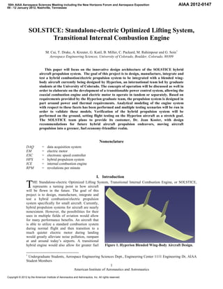
  • 1. 50th AIAA Aerospace Sciences Meeting including the New Horizons Forum and Aerospace Exposition AIAA 2012-0147 09 - 12 January 2012, Nashville, Tennessee SOLSTICE: Standalone-electric Optimized Lifting System, Transitional Internal Combustion Engine M. Cui, T. Drake, A. Kreuter, G. Kutil, B. Miller, C. Packard, M. Rahimpour and G. Soin 1 Aerospace Engineering Sciences, University of Colorado, Boulder, Colorado, 80309 This paper will focus on the innovative design architecture of the SOLSTICE hybrid aircraft propulsion system. The goal of this project is to design, manufacture, integrate and test a hybrid combustion/electric propulsion system to be integrated with a blended wing- body aircraft currently being designed by Hyperion, an international team led by graduate students at the University of Colorado. The concepts of operation will be discussed as well in order to elaborate on the development of a transitionable power control system, allowing the coaxial combustion engine and electric motor to operate in tandem or separately. Based on requirements provided by the Hyperion graduate team, the propulsion system is designed in part around power and thermal requirements. Analytical modeling of the engine system with respect to these facets has been performed and multiple testing scenarios will be run in order to validate these models. Verification of the hybrid propulsion system will be performed on the ground, setting flight testing on the Hyperion aircraft as a stretch goal. The SOLSTICE team plans to provide its customer, Dr. Jean Koster, with design recommendations for future hybrid aircraft propulsion endeavors, moving aircraft propulsion into a greener, fuel economy-friendlier realm. Nomenclature DAQ = data acquisition system EM = electric motor ESC = electronic speed controller HPS = hybrid propulsion system ICE = internal combustion engine RPM = revolutions per minute I. Introduction T HE Standalone-electric Optimized Lifting System, Transitional Internal Combustion Engine, or SOLSTICE, represents a turning point in how aircraft will be flown in the future. The goal of this project is to design, manufacture, integrate and test a hybrid combustion/electric propulsion system specifically for small aircraft. Currently, hybrid propulsion systems for aircraft are nearly nonexistent. However, the possibilities for their uses in multiple fields of aviation would allow for many performance benefits. An aircraft that is able to utilize a standard combustion system during normal flight and then transition to a much quieter electric motor during landing would greatly alleviate noise pollution, rampant at and around today’s airports. A transitional hybrid engine would also allow for greater fuel Figure 1. Hyperion Blended Wing-Body Aircraft Design. 1 Undergraduate Students, Aerospace Engineering Sciences Dept., Engineering Center 1111 Engineering Dr, AIAA Student Members 1 American Institute of Aeronautics and Astronautics Copyright © 2012 by the American Institute of Aeronautics and Astronautics, Inc. All rights reserved.
  • 2. efficiency (similar to a hybrid car) by decreasing fuel expenditure, allowing the combustion engine to operate more efficiently while the electric motor provides any remaining power necessary for flight. The SOLSTICE HPS is one facet of a larger program known as Hyperion. The Hyperion team is an international amalgamation, comprised of students from the University of Stuttgart in Germany, from the University of Sydney in Australia, and from the University of Colorado, represented by both undergraduate and graduate teams. Under the leadership of the CU graduate team, Hyperion is designing a model blended wing-body aircraft, seen in Fig. 1, with the intent of developing a cleaner, greener and quieter aircraft system. The SOLSTICE undergraduate team is responsible for the propulsion system of this new aircraft concept. The Hyperion team plans to fly the modeled aircraft in multiple flight modes, including cruise, quiet and dash, through the utilization of the SOLSTICE hybrid engine design. To achieve these different operational modes, the SOLSTICE engine controls two motors within the hybrid system either individually or in tandem: dash mode utilizes both the internal combustion engine and the electric motor while quiet mode uses the electric motor only. Cruise uses the combustion engine alone. SOLSTICE is designing the control system to operate these flight modes along with the physical HPS. II. System Configuration The SOLSTICE hybrid propulsion system makes use of two separate engines, one electric motor (EM) and one internal combustion engine (ICE) to drive the propeller. A patent-pending gearbox converts the input torques of these two engines into one output torque, turning the propeller shaft. Power sources for the EM and ICE consist of batteries and fuel, respectively. By utilizing the EM and ICE either concurrently or independently the various flight modes can be achieved such as EM only for quiet operation or EM and ICE concurrently for maximum power. The entire system, excluding power supplies, is placed on a single base plate to allow for ease of integration and structural rigidity. The overall system is constrained in mass and volume as it is necessary for the HPS to fit inside the Hyperion aircraft. During the fall semester design phase, multiple analytical models were produced (thermal, structural stress and strain, and power) in order to ensure that the system will provide the necessary power to successfully fly the Hyperion aircraft. Figure 2 illustrates the propulsion Figure 2. SOLSTICE Hybrid Propulsion System Configuration. system configuration to be manufactured in the spring semester, 2011. This configuration was designed iteratively over the course of the fall semester utilizing a systems engineering approach, working from broad to specific requirements. Initially the team worked with advisors and clients to develop a preliminary goal and set of objectives. As is common practice, top level requirements were devised based on these objectives and on certain parameters such as the overall aircraft mass restrictions. During the Preliminary Design phase, these requirements were broken down to a subsystem level where enough detail was defined in order to narrow down selection of components. Trade studies were performed and the design continued with those selected. The overall system architecture was continually observed, allowing for a constant systems engineering perspective. The results of these studies and their impact on the design were presented to a panel of aerospace engineering faculty in a Preliminary Design Review (PDR). In the following Critical Design phase, parts were selected and prototyping of major risks in order to find mitigating solutions was performed. During the Critical Design Review (CDR) modifications to the preliminary system architecture were presented by the team as a part of the complete system, its components and the analysis behind their design/selection. 2 American Institute of Aeronautics and Astronautics
  • 3. This educational process goes hand-in-hand with aerospace industry practices. Project definition is the first and foremost step to the design process even with the existence of a multitude of unknowns at the time. This process- and the process to follow in the spring semester- has invaluably prepared the SOLSTICE team for any future engineering endeavors. III. System Modeling Modeling physical and conceptual systems is a necessary process within engineering. The ability to predict performance increases the probability of successfully completing a project. Prediction through modeling can produce a more thorough understanding of a system’s characteristics and interdependencies. In most situations, modeling, combined with testing, generates this understanding earlier and more efficiently than testing alone. Increasing efficiency not only allows a project to be completed in a shorter period of time, but also decreases the amount of funds necessary for project completion. A. Power Modeling SOLSTICE’s main requirement from Hyperion, derived from the desired multiple flight modes, is that either the electric motor or the internal combustion engine must supply the aircraft with 2 horsepower. During the design phase of the project, a simple, yet effective, power model was developed to ensure SOLSTICE’s HPS could meet Hyperion’s requirement. The model takes into account all major functional inefficiencies to predict the propulsion system’s power Figure 3. Power Model Component Efficiency. output. The major functional inefficiencies within the system include friction losses from gearing and losses within the electric motor linked to converting electrical power to mechanical power. Figure 3 represents the structure of the model visually. It is predicted through analysis that the gearing is 75% efficient with a confidence of 70%. The confidence is based on the possible range of coefficients of friction for meshing gears. The electric motor was assigned an efficiency of 80% based on manufacturer specifications and lessons learned from previous experience. One of the novelties of the SOLSTICE Figure 4. Aircraft Flight Modes in Concept of Operations. engine is the capability of running on different modes. This ultimately allows the aircraft to also fly at different flight modes and can be used to optimize and limit fuel consumption. An example of how the variable flight operations can be utilized in an aircraft is shown in Fig. 4. Figure 4 shows how an aircraft can take advantage of the engine to achieve periods of maximum velocity, minimal fuel consumption, and regular flight operations. This concept was the foundation of the project: to conceive and build an engine capable of performing each of these flight modes. Each flight mode has a power output necessary to fly the Table 1. Required Propeller Output for Flight Modes aircraft as desired. The Flight Mode Power (W) Velocity (m/s) Ideal Prop RPM power output needed for Takeoff 1500 >7.6 1795.3 each flight mode is Cruise 750 24.3 5740.2 summarized in Table 1. Quiet 410 13.6 3212.6 The output power is the Dash 1500 32.4 7653.5 power required from the Landing 460 9.9 2338.6 propeller. 3 American Institute of Aeronautics and Astronautics
  • 4. B. Thermal Modeling Of major concern in integration of the hybrid propulsion system with the aircraft is the generation of heat by the system. Because the propulsion system is located within the fuselage of the aircraft, the heat generated by the system will heat the surrounding aircraft structure and skin. The skin of the aircraft is fabricated from a fiberglass-epoxy material that must remain below 60oC in order to avoid material softening. To determine the thermodynamic characteristics of the system, two assumptions were made. The first assumption is that all power lost from inefficiencies in the system is fully converted to heat. The second assumption is no force convection over the system, only free convection. These two assumptions provide a worst case scenario of the propulsion system during operation. Through lumped analysis, it was determined that the system would produce 700W of heat via the three mechanisms of heat transfer. The heat transfer present within the engine cavity is shown in Fig. 5. In order to mitigate the risk of weakening the fiberglass epoxy’s integrity, forced convection over the system will be required. This shall be accomplished by implementing a duct into the nose of the aircraft. Further analysis of the system showed that a relation between the necessary forced convection properties, such as the convection Figure 5. Heat Transfer Model. coefficient and the flow speed, could be determined as a function of the total heat transfer. The relation is shown in Fig. 6 which gives the convection coefficient and flow speed required to keep fiberglass skin under 60oC. The model proved that as the heat transfer decreases, the required airflow over the system decreases. It was determined that a heat transfer of 700W is the worst case scenario thus the design team is confident that passive air cooling from the Hyperion aircraft will be sufficient for operational temperature. 150 Forced Convection Model 17 Convection Coefficient, h [W/m 2 K] Airflow Speed, V [m/s] 16 15 100 Mass Flow Rate (g/s) 14 13 50 12 11 10 0 0 100 200 300 400 500 600 700 9 270 275 280 285 290 295 300 Heat Transfer Q [W] Anticipated Ambient Air Temperature (K) Figure 6. Forced Convection Required. Figure 7. Necessary System Cooling. Further modeling has provided a mass flow rate necessary for operation, based on expected atmospheric conditions and the required interior temperature limit of 60 oC. The model predicts a mass flow rate range of 9.5 to 16.5 g/s. Currently a mass flow rate equal to or greater than 34 g/s is expected to account for the worse case scenario and a factor of safety of 2. Figure 7 displays the mass flow rate’s dependence on the anticipated freestream temperature range. The model assumes steady state flow, the air is perfectly mixed within the system’s cavity, and heat transfer is limited to convection within the cavity and conduction through the aircraft’s skin. 4 American Institute of Aeronautics and Astronautics
  • 5. IV. System Verification The next step following system modeling is performing tests with real hardware and software. The data obtained from system and subsystem tests can then be analyzed and used to verify the different system models. In order for these tests to represent the models accurately, the hardware including electronics and software used during the tests should be the actual flight hardware and not prototypes. System verification tests are the final step before the overall system design can be validated and approved for flight. As such, it is essential that these tests be performed following detailed laid out procedures as well as be repeated multiple times to obtain accurate data. A. Power Testing One of the primary requirements that the SOLSTICE HPS has to supply a minimum of 2 horsepower from its Electric Motor and Internal Combustion engine. These power requirements are essential for the Hyperion aircraft to achieve flight and also to verify their Concept of Operations. The SOLSTICE team performed tests on its HPS and used the data to verify the power output from the system. The primary apparatus used for these tests was a reaction force dynamometer which utilizes a force transducer to measure the reaction torque from the HPS. This is coupled with a voltage expander and an RPM sensor which together measure the input power to the system. The data obtained from these two sensors are then analyzed and compared in order to obtain the efficiency curves for the different components of the HPS. The setup for this apparatus can be seen in Fig. 8. 100 95 SOLSTICE EM Efficiency [%] Figure 8. Dynamometer with EM 90 Attached. Figures 9, 10 and 11 represent the efficiency 85 and power curves for the most critical components of SOLSTICE's HPS namely the 80 Electric Motor and the propeller. Using the dynamometer, SOLSTICE has been able to 75 quantify the efficiency of both these EM Efficiency components. Polyfit 70 Figure 9 shows the efficiency curve for the 4000 4500 5000 5500 6000 6500 7000 7500 SOLSTICE Electric Motor plotted against its RPM RPM. The test was performed between a range Figure 9. EM Efficiency vs. RPM. of 5 to 20 Amps at intervals of 5 Amps in order to replicate the desired flight conditions for the EM. The design specifications for the EM provided by the manufacturer rate the efficiency to be approximately 80%. From the EM dynamometer test, this specification was verified and the efficiency of the motor was approximated to be 85% under the desired flight operation conditions. In order to verify that the SOLSTICE Electric Motor has the required power to satisfy the given power requirement, another dynamometer test was performed to quantify the power output of the motor. This was again plotted against RPM and is shown in Fig. 10. Due to structural limitations of the SOLSTICE Dynamometer, the test could not be performed at the optimum range of input current for the EM. However, the test performed provided the relation through which the SOLSTICE team could then extrapolate the power output at higher current values. Through these analysis, it was determined that at an RPM of 8750, the SOLSTICE EM will output 1500 Watts of power which includes the 85% EM efficiency determined from the previous test. This power output is equivalent to the 2 horsepower requirement. Hence, with the help of this test and its analysis, SOLSTICE has been able to successfully verify its power requirements. 5 American Institute of Aeronautics and Astronautics
  • 6. 800 Although, the power requirements give to SOLSTICE by the Hyperion 700 team accounted for a propeller efficiency of 50%, SOLSTICE did SOLSTICE EM Output Power 600 another dynamometer test to verify the efficiency of the actual flight propeller. 500 This was done in order to be thorough and obtain accurate power curves for 400 the HPS. Figure 11 shows the efficiency 300 curve of the flight propeller plotted against RPM along with a least squares 200 regression curve denoted as "Polyfit". The profile changes because 100 SOLSTICE is using a single speed 4000 4500 5000 5500 6000 6500 7000 7500 propeller which is designed to have a RPM Figure 10. EM Output Power in Watts(Including EM Efficiency) maximum efficiency at a single point. vs. RPM. The approximate propeller efficiency 70 determined from this test is 55% to 65% which is higher than what the Hyperion 60 requirements accounted for. Thus, the analysis for this test further strengthens the verification 50 of the SOLSTICE power requirements. Efficiency [%] 40 30 20 10 Propeller Efficiency Polyfit 0 1500 2000 2500 3000 3500 4000 4500 5000 5500 6000 RPM Figure 11. Propeller Efficiency vs. RPM. B. Thermal Testing To verify the thermodynamics and heat transfer of the hybrid propulsion system, tests are to be conducted to verify the requirements set forth by the structural integrity of the aircraft. The tests include measuring the thermal output from each component in the system. The major components that must be considered from a thermodynamic perspective are the internal combustion engine, electric motor, electronic speed controller, gearbox, and electronic circuits. Each component has inefficiencies where power losses generate heat. To experimentally determine the heat transfer of the system components, a test box is utilized that has the same geometry as the engine cavity within the aircraft. The test box also utilizes a polycarbonate material that has similar thermal properties as the fiberglass skin of the aircraft. A representation of the test box is shown in Fig. 12. In addition, the location of the temperature Figure 12. Thermal Test Bed Setup. sensors placed throughout the box to measure the 6 American Institute of Aeronautics and Astronautics
  • 7. change in ambient temperature is shown. For the tests, seven LM 34 temperature sensors are to be used that measure the ambient temperature in Fahrenheit. Using the Fahrenheit sensors allows for a better signal to noise ratio than that of the Celsius LM35 sensors. The first thermal test performed gave insight into how hot the engine cavity would get during the taxi portion of the flight. To simulate this, the internal combustion engine is to run on idle with the engine completely sealed within the box. During taxi, the propeller wash is negligible and is considered zero to test a worst case scenario. The test results, shown in Fig. 13, proved that over a span of 17 minutes, the temperature throughout the engine cavity does increase with the engine in idle. The maximum temperature measured during the 17 minute idle was 40oC located directly above the idling engine. This is still below the maximum 60oC required be 45 Sensor 1 the aircraft structure. When the aircraft takes to Sensor 2 40 the air, the propeller will generate prop wash that Sensor 3 will flow over the system and provide passive air Sensor 4 35 Sensor 5 cooling. Ambient Temperature [C] Sensor 6 Testing of the electric motor and electronic Sensor 7 30 speed controller are still to be performed however from preliminary dynamometer testing, the team 25 is confident that these component will not generate any substantial heat and any forced 20 convection will be sufficient for the required cooling. In addition, the gearbox will use lubrication that has the appropriate viscosity that 15 will ensure minimal heat generation. Finally, a full system test is to be performed several times 10 0 2 4 6 8 10 12 14 16 18 20 that will follow the aircraft mission and concept Time [min] of operations. This test will be performed a Figure 13. ICE Idle Results, No Forced Convection. multitude of times to ensure reliability in the thermodynamics and heat transfer of the hybrid propulsion system to the aircraft. V. System Applications The advantage of the SOLSTICE system comes from the ability to change between fundamentally different types of engines. The ICE has the advantage of burning fuel, reducing the overall weight of the aircraft over time. The EM has the advantages of quiet operation relative to the ICE and it has the ability to run at higher altitudes. A typical use of the SOLSTICE engine will cycle the ICE and EM based on the flight regimes. The flight regimes include a dash mode which utilizes the power of both engines to reach a maximum speed for the aircraft. This engine mode also has the ability to provide significant thrust for takeoff through running the two engines together. This allows the selected engines to be smaller and tailored more towards the maximum thrust needed in cruise conditions. The next flight regime utilizes the EM only. This flight regime can be considered a quiet mode and can be used in urban areas where noise levels are an issue. This mode can be used for unobtrusive surveillance of targets as well. It has also been proposed that this flight regime be used as a high altitude mode, allowing the aircraft to fly at higher altitudes than those at which an ICE is capable of operating. The ICE-only flight regime can be thought of as a general purpose mode. By burning the majority of the stored fuel during takeoff and climb the thrust needed in cruise would be minimized for a higher percent of the mission duration. In the future the ICE may be made to use a bio-fuel such as biodiesel to decrease its environmental impact. This could potentially lower the fuel cost of operations which would be further offset by the use of the electric motor. The basic design of the SOLSTICE engine is not limited only to a propulsion system. A further application would be as a portable generator for remote operations such as Antarctica or disaster relief. This would involve replacing the EM with a generator and the propeller with a turbine blade optimized for power generation. The system provides near-limitless power from the wind. This is augmented with the ICE as a traditional gas generator. By relying on the gas generator only when there is no wind the operation would need to carry less fuel for their power needs. In windy places the ICE could be seen as an emergency option. The combination of the two sources would reduce the total weight of the system and make it more portable than the two systems individually. 7 American Institute of Aeronautics and Astronautics
  • 8. VI. Conclusion Although the application hybrid technology in aircraft has only recently become a topic of serious interest in the aerospace community, it is a necessary technology in ensuring that the aircraft of the future are both fuel efficient and environmentally friendly. The SOLSTICE project provides further development in the field of hybrid aircraft propulsion through testing and modeling to verify the validity of such a system in aircraft. Current applications of the SOLSTICE project are limited to UAV markets due to current battery technologies. However, with an ever increasing interest in both UAV application and lessening carbon foot-prints, the SOLSTICE system is relevant in today’s aircraft industry. The current state of testing verifies that the EM meets the power requirements and that the propeller exceeds expected efficiency. Through the design process of the HPS, many valuable lessons have been learned including the importance of communication within the team and with the customer. Since the project represents a global effort between students from various countries it is necessary that communication is clear and concise to ensure that any problems that may arise are mitigated diligently and efficiently. By developing a system with the potential to rely less on fossil fuels for energy this project represents a global interest in ensuring that the future of aircraft propulsion is cleaner and safer. Acknowledgments The authors thank Dr. Jean Koster and Dr. Donna Gerren for their continued advice on this project. The team also appreciates the strong support and guidance received from Cody Humbargar and the entire Hyperion team (Scott Balaban, Derek Nasso, Andrew Brewer, Julie Price, Chelsea Goodman, Eric Serani, Derek Hillery, Alec Velazco, Mark Johnson, Richard Zhao, and Tom Wiley). We also thank the international partner teams from the University of Stuttgart in Germany and from the University of Sydney in Australia who helped make this project a fascinating and unique learning experience. Funding for this project is provided in part by The Boeing Company, eSpace Inc., and NASA under grant NNX09AF65G. 8 American Institute of Aeronautics and Astronautics