Downloaded 232 times
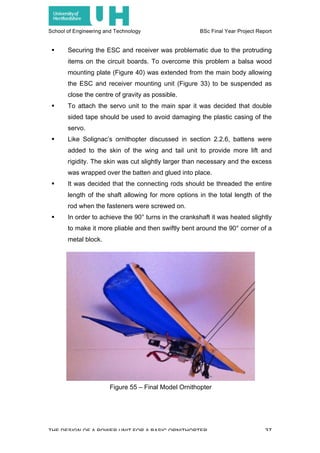
![School of Engineering and Technology BSc Final Year Project Report
THE DESIGN OF A POWER UNIT FOR A BASIC ORNITHOPTER 3
2.2. Literature Review
2.2.1.Origin of the Ornithopter
Leonardo da Vinci and Otto Lilienthal are two of the most notable names
associated with the primitive stages of human developed and human powered
flapping wing flight. Ornithopters can be traced back even further than da
Vinci and Lilienthal to Greek mythology where Homer’s Daedalus constructed
bird like wings from goose feathers and beeswax to escape imprisonment
enforced by King Minos, the word ‘ornithopter’ actually derives from Greek
where ‘ornithos’ translates to ‘bird’ and ‘pteron’ to ‘wing’ [1]
, however da Vinci
and Lilienthal were pioneers of progressing ornithopters into useful vehicles
by studying the natural flight of birds and wing shapes. Consequently for
ornithopters the development of aeroplanes and helicopters gradually
diminished the interest, and indeed requirement, for flapping wing flight. Yet,
as the development of aircraft in use today begins to peak and environmental
awareness grows ever more poignant interest in flapping wing flight has been
re-kindled.
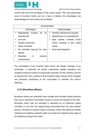
2.2.2.Flapping Wing Flight
Similarly to avian vertebrates, ornithopters can only produce the thrust
required to fly through the flapping of wings, a unique motion that does
without the requirement of a propeller or rotating wing installed on more
traditional aircraft. The complexity of bird wings have occupied scientists and
engineers for decades; the shape, size, angle of attack, flap frequency,
layering of feathers and muscular construction of a bird’s wing have been the
subject of numerous studies.](https://image.slidesharecdn.com/finalyearprojectreport-150521183120-lva1-app6891/85/Final-Year-Project-Report-12-320.jpg)
![School of Engineering and Technology BSc Final Year Project Report
THE DESIGN OF A POWER UNIT FOR A BASIC ORNITHOPTER 4
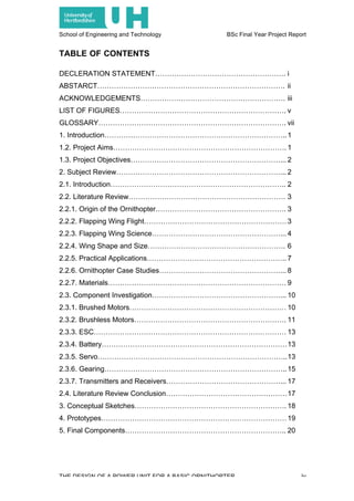
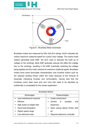
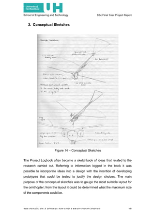
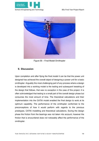
2.2.3.Flapping Wing Science
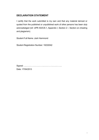
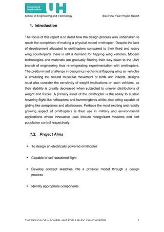
Much like an aeroplanes aerofoil a bird’s wing creates high-pressure regions
around the lower surface and low-pressure regions along the upper surface
thus allowing the bird to glide [2]
. In order to gain height the bird increases the
flapping frequency of its wings, which forces larger deflections of air
downwards resulting in the reactive force of lift.
The complex nature of a bird’s wing occurs during the transition from a down-
stroke, to produce lift, to an up-stroke, where the cycle restarts. A common
misconception is that the up-stroke should produce a force similar to that of
the down-stroke, thus equalling the forces. YouTube video maker
SmarterEveryDay [3]
uses slow motion film to illustrate how bird wings function
and do not conform to the misconceptions. He explains that during the up-
stroke feathers separate to allow air to flow through the wing, additionally the
bird is capable of altering the angle of their wing to form the most streamline
and aerodynamically efficient shape, both of these actions therefore enable
the bird to ‘provide downward thrust on a backward stroke [3]
. Current
technology does not have the capability to replicate birds’ wings in such
delicate detail; instead ornithopters are resigned to mirroring bird wing
shapes, sizes and flapping frequencies. The forces acting on a flapping wing
can be quantified and calculated when using a simpler aerofoil as opposed to
attempting to replicate the complicated natural mechanics of a real avian
wing, for example, the extensive research that has already been conducted
on aeroplane aerofoils can be implemented for the theoretical reckoning of
flapping wing dynamics.
Figure 1 – Bird Wing Aerofoil [2]](https://image.slidesharecdn.com/finalyearprojectreport-150521183120-lva1-app6891/85/Final-Year-Project-Report-13-320.jpg)
![School of Engineering and Technology BSc Final Year Project Report
THE DESIGN OF A POWER UNIT FOR A BASIC ORNITHOPTER 5
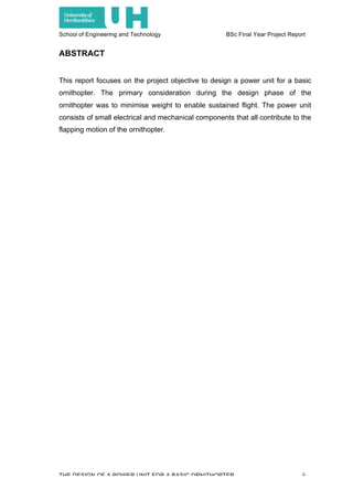
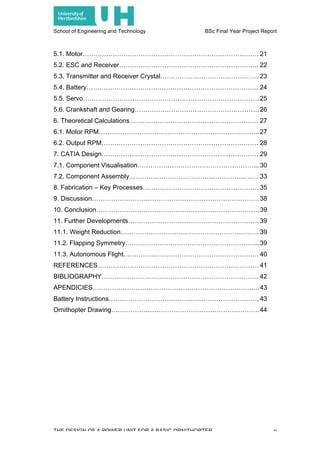
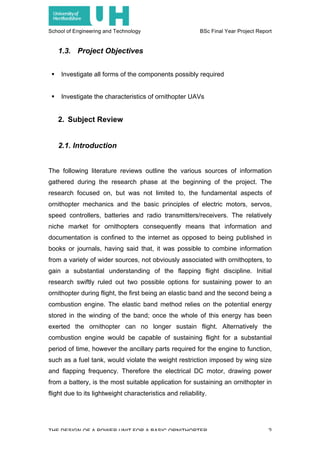
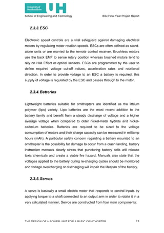
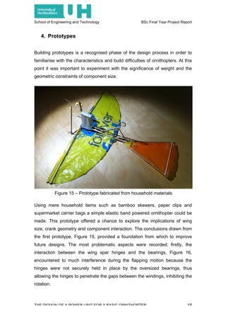
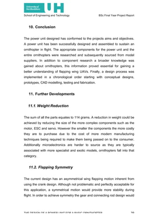
Figures 2 and 3 illustrate how the thrust of a flapping wing can be related to
vectors of resultant forces where U∞ is the airflow due to forward motion, Uz is
the airflow due to the flapping motion and Ur is the relative airflow.
Figure 4 demonstrates in further detail how the downstoke of a birds’ wing
produces lift and thrust in the same movement.
Figure 2 – Upstroke with negative lift [4]
Figure 3 – Downstroke [4]
Figure 4 – Force and speed for the downstroke [4]](https://image.slidesharecdn.com/finalyearprojectreport-150521183120-lva1-app6891/85/Final-Year-Project-Report-14-320.jpg)
![School of Engineering and Technology BSc Final Year Project Report
THE DESIGN OF A POWER UNIT FOR A BASIC ORNITHOPTER 6
In Figure 4 it becomes apparent that the aerodynamic force (K) is almost
perpendicular to the track of the birds’ wing, furthermore the downstroke
generates lift (L) and thrust (T), this concept has also been explored by Henk
Tennekes who concluded that ‘the thrust to lift ratio is equal to the ratio of the
downward speed of the wing and the forward speed of the bird (w/V)’ [4]
. As
well as identifying speed and force vectors for a flapping wing it is also
possible to distinguish physical deformations that are imposed on the wing
during flight. In particular, bending and twisting forces can be detrimental to
any wing, especially man-made ones that are constructed from material that
eventually fatigues and fails. The flapping motion make the wing susceptible
to bending forces at the root where the power of the motor is being transferred
and converted to thrust. In addition to the fore mentioned forces, vibration can
also cause distress to an ornithopter in the shape of a force that will gradually
lessen the rigidity of the structure. Vibration forces can form from asymmetric
wing flapping, where the wings are not flapping in sync (symmetrically), but
the most common source of vibration is from the motor and gearing system
that will be rotating at high speeds. Such vibration can be controlled by
balancing the rotation, problems occur when an unbalanced object is rapidly
rotated and eventually ‘shakes’ itself apart.
2.2.4.Wing Shape and Size
As mentioned in section 2.2.3 scientific research has diligently explored the
reasons behind the differing shapes and sizes of avian vertebrates wings. The
behaviour and lifestyle of birds dictates the type of wing they have evolved to
bear. Research has revealed that predatory birds, like Hawks and Eagles,
have developed wings capable of enabling them to fly quickly and change
direction rapidly, whereas birds that traverse large distances over landmass
and oceans typically have wings suited to gliding, resulting in energy efficient
flight. Ornithopters tend to adopt wing shapes that provide the most stable
platform for stable flight and as previously mentioned the intricate detail of a
bird’s wing is not directly mirrored but instead the outline shape and span is](https://image.slidesharecdn.com/finalyearprojectreport-150521183120-lva1-app6891/85/Final-Year-Project-Report-15-320.jpg)
![School of Engineering and Technology BSc Final Year Project Report
THE DESIGN OF A POWER UNIT FOR A BASIC ORNITHOPTER 7
more closely observed. As well as endeavouring to provide stability for the
ornithopter the wing design also considers the required lift generation to
sustain it in flight. Heavier ornithopters require larger wings or more frequent
wing beats, but because the stresses of rapid wing flapping can be
problematic a larger wing is usually preferred. Consequently larger wings
require more powerful motors to provide enough leverage for the downward
and upward strokes. Martin Simons discusses model aerodynamics in his
book Model Aircraft Aerodynamics and explains that a semi-elliptical wing has
been mathematically proven to be the most stable because at all speeds it
provides constant downwash, equal load distribution along the wing and stalls
simultaneously at each point [5]
. Stability is an imperative attribute to make the
ornithopters handling characteristics more forgiving for the pilot.
2.2.5.Practical Applications
This section will diverge slightly from the scientific analysis of ornithopters and
focus on the reasons for their use and the environment in which they are
deployed. Military interest in ornithopters has re-focused the interest on
flapping wing UAVs, particularly where there is an opportunity for companies
to gain capital from developing and delivering ornithopters for practical uses.
The United States Darpa department (the Pentagon’s advanced research
unit) is an exceptional example. Darpa were commissioned to manufacture a
micro-ornithopter, capable of hovering and carrying its own power source,
with the intention of using it for covert indoor missions such as bugging a
room with hidden listening devices or transmitting audio and video to locations
up to one kilometre away. Darpa claim that the micro-ornithopter is more
aerodynamically efficient than remote control helicopters/aeroplanes, a claim
measured by the low Reynolds Number (airborne efficiency) [6]
. Moreover,
military interest extends beyond small-scale ornithopters, they also intend to
capitalise on the ornithopters resemblance to birds and insects for
inconspicuous recognisance missions. Natural environmentalists are also
beginning to understand the advantages of ornithopters, for example, the](https://image.slidesharecdn.com/finalyearprojectreport-150521183120-lva1-app6891/85/Final-Year-Project-Report-16-320.jpg)
![School of Engineering and Technology BSc Final Year Project Report
THE DESIGN OF A POWER UNIT FOR A BASIC ORNITHOPTER 8
Colorado Division of Wildlife has used ornithopters to aid the survival of an
endangered bird species, the Gunnison Sage Grouse. Further commercial
uses extend to the protection of commercial aircraft from bird strikes at take-
off and landing, Schiphol Airport in Holland has seen success with this
method.
2.2.6.Ornithopter Case Studies
To gain a further understanding of how ornithopters work it was important to
research existing models to identify what made them successful and attempt
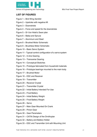
to identify the key components required for a successful design. Dr Erich Von
Holst created some of the early successful ornithopters in the 1940s, his
Swan, Brimstone Butterfly and Thrust
Wing models incorporated wings
derived from his research on biological
and bird flight. However his models
were powered by elastic bands, as the
micro-electronic components available
nowadays were not present in the
1940s. Jean-Louis Solignac’s design
(2000) draws attention because he
moved away from the tradition of
incorporating a tail unit. Battens in the
aerofoil create a downward camber
allowing the model to fly in a stable
attitude [7]
. More advanced
ornithopters have come in the form of Sean Kinkade’s Park Hawk and Slow
Hawk. Both models have been designed with mass production in mind,
therefore they are relatively simple to construct and are made up of
replaceable parts interchangeable with new parts in case of breakages. By
using modern components Sean Kinkade has created an efficient design
capable of being used by ornithopter hobby enthusiast. The models are
powered by a ‘high KV brushless outrunner motor and brushless ESC and is
Figure 5 – Dr Von Holst’s Swan plan](https://image.slidesharecdn.com/finalyearprojectreport-150521183120-lva1-app6891/85/Final-Year-Project-Report-17-320.jpg)
![School of Engineering and Technology BSc Final Year Project Report
THE DESIGN OF A POWER UNIT FOR A BASIC ORNITHOPTER 9
designed to fly on 2 cell lipo packs’ [8]
. Consequently the use of cutting edge
electrical components, materials and fabrication techniques (CNC) comes at a
cost to the consumer with the Park Hawk retailing at £188.
2.2.7.Materials
Traditional model building materials have always catered for designs of a
lightweight nature whilst providing acceptable levels of strength. UAVs will
always be susceptible to damage from crashes and manoeuvring stresses
because they can operate at considerable speeds at altitude. Materials such
as woods, plastics and metals can be purchased from hobby shops and DIY
stores, making them the material of choice for most aero modellers. Balsa is
typically the most popular wood for its
diversity for model building; cuts come in a
variety of sizes and grain directions. Balsa
strength is acknowledge to be better than
steel when comparing the tensile strength to
density ratio, however, like all fibrous
materials the best loading strength is
obtained when the load is with the grain as
opposed to across it. Spruce wood is a
denser material than Balsa and is therefore
heavier but has the advantage of being
stronger. Spruce wood is suitable for
applications where stresses may overcome
Balsa and eventually damage it. The plastics
available to model builders are usually
moulded into pre-determined shapes as
most builders do not have the facilities such
as injection moulders and vacuum formers
to fabricate their own designs. Aluminium
and steel are favoured for their attributes of
strength and workability where they can be
Figure 6 – Balsa and Spruce
Figure 7 – Aluminium and Steel](https://image.slidesharecdn.com/finalyearprojectreport-150521183120-lva1-app6891/85/Final-Year-Project-Report-18-320.jpg)
![School of Engineering and Technology BSc Final Year Project Report
THE DESIGN OF A POWER UNIT FOR A BASIC ORNITHOPTER 14
gears, a motor, a feedback potentiometer and an amplifier [9]
. Firstly, gears
are fabricated form plastic or metal depending on their intended use. Plastic
gears are suitable for smaller models requiring less powerful servos to
manipulate control surfaces under less stress whereas metal gears are suited
to servos mounted on models weighing over 2.5kg. Secondly, brushed motors
make a re-appearance for use in servos as they are robust and can be
obtained at low costs. The iron armature at the core of the motor can be
problematic when a servo with extremely fast responses to control inputs are
required because of the inertial/momentum forces of a heavy material. The
feedback potentiometer is an ingenious component mounted to a small circuit
board in the servo casing that can determine the position of the output arm by
using a variable resistor to create a voltage determining its precise location.
This is an important act that has to be carried out so that the user can
manipulate the output arm in the desired manner during all phases of the
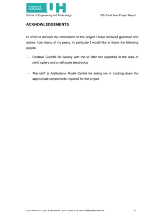
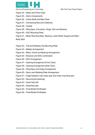
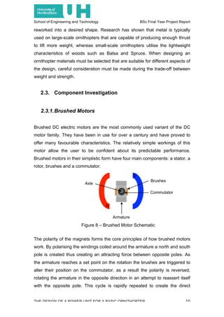
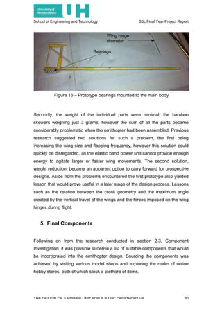
operation. Finally, amplifiers are digital microcontrollers that control the
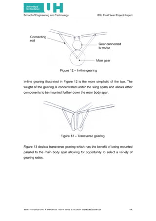
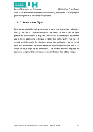
torque, speed and accuracy of the servo. A. W. Richmond characterises servo
schematics (Figure 10 & 11) in his book Servos and Steppers that illustrate
how servo motors are connected to their loads, among other components.
Figure 10 – Basic Servo System [10]](https://image.slidesharecdn.com/finalyearprojectreport-150521183120-lva1-app6891/85/Final-Year-Project-Report-23-320.jpg)
![School of Engineering and Technology BSc Final Year Project Report
THE DESIGN OF A POWER UNIT FOR A BASIC ORNITHOPTER 15
2.3.6.Gearing
Gears on ornithopters work the same way as those found in automobiles and
aircraft turboprop engines. They are required to reduce the shaft power of the
motor and convert it into controllable RPMs required to drive the axle of a car,
rotate the propeller of an aircraft or flap the wings of an ornithopter. The
number and size of gears is referred to as a gearing ration and determines the
final power output being delivered by the motor after the power has been
transferred through the gears. Torque is also an important factor when
considering gearing ratios as larger gears provide more torque to overcome
inertial forces. Metallic gears are less favoured over plastic gears for
ornithopters as they are too heavy; instead plastic gears are utilised for their
weight, wear resistance and ability to absorb backlash shocks. Ornithopter
weight restrictions dictate that gears should be kept to a minimum and remain
as simple as possible, they should also be installed as close to the centre of
lift as possible in an attempt to balance the overall weight of the ornithopter.
Research has yielded that in-line and transverse configurations are the most
suitable arrangement for minimising the space required and the number of
gears necessary.
Figure 11 – Typical control configuration of a servo-system [10]](https://image.slidesharecdn.com/finalyearprojectreport-150521183120-lva1-app6891/85/Final-Year-Project-Report-24-320.jpg)
![School of Engineering and Technology BSc Final Year Project Report
THE DESIGN OF A POWER UNIT FOR A BASIC ORNITHOPTER 41
REFERENCES
[1] Wikipedia, Ornithopter, [Online] Available at:
http://en.wikipedia.org/wiki/Ornithopter [Accessed 7th October 2012]
[2] Avian Biology, Ornithology – Lecture Notes 2 – Bird Flight 1, [Online] Available at:
http://people.eku.edu/ritchisong/554notes2.html [Accessed 12th October 2012]
[3] SmarterEveryDay, How Bird Wings Work, [Online] Available at:
http://www.youtube.com/watch?v=4jKokxPRtck [Accessed 20th
October 2012]
[4] Tennekes, H. (1997) The Simple Science of Flight: From Insects to Jumbo Jets,
Massachusetts: The MIT Press, Page 68
[5] Simons, M. (1987) Model Aircraft Aerodynamics, Second Edition, London: Argus
Books Ltd, Page 63-66
[6] Popular Science (2009) Darpa’s First Robotic Ornithopter, Flies Like a
Hummingbird, [Online] Available at: http://www.popsci.com/military-aviation-amp-
space/article/2009-07/darpa-tests-first-robotic-ornithopters [Accessed 2nd December
2012]
[7] Jean-Louis Solignac (2000) Aux Ornithoptères à Élastiques (The Elastic
Ornithopter), [Online] Available at: http://ovirc1.free.fr/solignac-ornitho.htm [Accesses
12th December 2012]
[8] Hobby Technik, Park Hawk 4, [Online] Available at:
http://flappingflight.com/inc/sdetail/777 [Accessed 11th December]
[9] RC Model Reviews, How Do RC Servos Work?, [Online] Available at:
http://www.rcmodelreviews.com/howservoswork.shtml [Accessed 18th December
2012]
[10] Richmond, A. W. (1999) A Practical Engineers Handbook: Servos and Steppers,
Croydon: Kamtech Publishing Ltd, Pages iv & 12](https://image.slidesharecdn.com/finalyearprojectreport-150521183120-lva1-app6891/85/Final-Year-Project-Report-50-320.jpg)

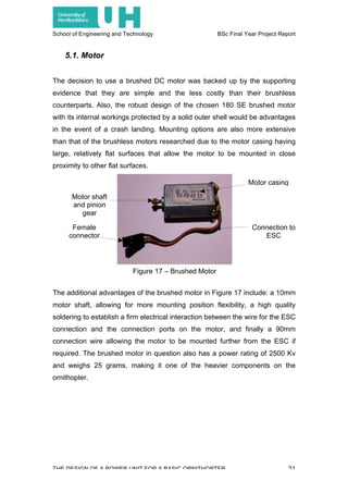
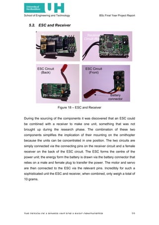
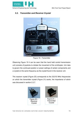
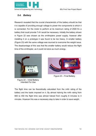
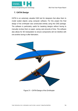
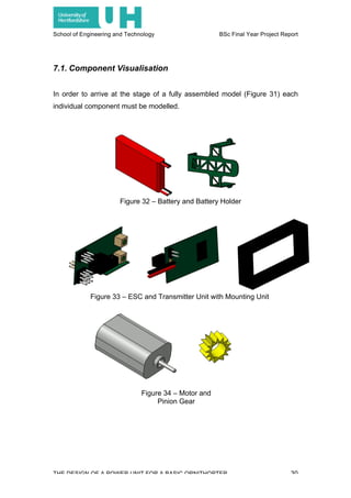
This document is a project report for a BSc in Aerospace Technology that details the design of a power unit for a basic ornithopter. It includes a literature review of ornithopter mechanics, components, and case studies to inform the design. Prototypes were fabricated and theoretical calculations were performed before finalizing the design in CAD software. The power unit consists of small electrical and mechanical components like a motor, gearing system, servo, and electronics to enable the flapping wing motion of the ornithopter.


