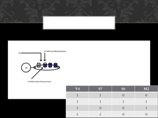
Project Supervisor:
Sir Rizwan
Group Members:
Jawad Zaeem 080338
Ali Abbas Naqvi 080309
Faisal Anwar 080325
INDUSTRIAL MECHATRONICS PROJECT
• Our project was to design a material mixing and bottle filling
station.
• There are three containers with level sensors “S1 S2 S3” which
determines the presence of the material in containers.
• After detecting material in all three containers their respective valves
are opened “V1 V2 V3” and another large container starts filling.
• This large container has two sensors “S4 and S5” which determines
the upper and the lower limit of the material.
• When lower sensors detects the material it starts mixing via motor
“M1” till upper limit has reached then it stops and a “Ready” bit is
set to logic high indicating material is present for filling purpose.
DESCRIPTION
DIAGRAM FOR THE MIXING
PROCESS
TRUTH TABLE
Inputs Outputs
S1 S2 S3 V1 V2 V3
0 0 0 0 0 0
0 0 1 0 0 0
0 1 0 0 0 0
. . . . . .
. . . . . .
. . . . . .
1 1 1 1 1 1
• After “Ready” bit is set to logic 1 conveyor belt starts moving via motor
“M2” which continues to run until sensor “S7” detects the presence of the
bottle after which motor is switched off and valve “V4” is opened and
starts filling bottle till the sensor “S6” the level sensor detects the liquid
level .
• Then again “V4” is closed and conveyor starts moving this whole process
continues for 6 bottles after which “Feed required” bit is set indicating that
material is finished and ready to be refilled.
• The process is on next slide.
BOTTLE FILLING STATION
V4 S7 S6 M2
1 1 0 0
1 1 1 1
1 0 0 1
1 1 0 0
Thank You

PLC Project

  • 2.
    Project Supervisor: Sir Rizwan GroupMembers: Jawad Zaeem 080338 Ali Abbas Naqvi 080309 Faisal Anwar 080325 INDUSTRIAL MECHATRONICS PROJECT
  • 3.
    • Our projectwas to design a material mixing and bottle filling station. • There are three containers with level sensors “S1 S2 S3” which determines the presence of the material in containers. • After detecting material in all three containers their respective valves are opened “V1 V2 V3” and another large container starts filling. • This large container has two sensors “S4 and S5” which determines the upper and the lower limit of the material. • When lower sensors detects the material it starts mixing via motor “M1” till upper limit has reached then it stops and a “Ready” bit is set to logic high indicating material is present for filling purpose. DESCRIPTION
  • 4.
    DIAGRAM FOR THEMIXING PROCESS
  • 5.
    TRUTH TABLE Inputs Outputs S1S2 S3 V1 V2 V3 0 0 0 0 0 0 0 0 1 0 0 0 0 1 0 0 0 0 . . . . . . . . . . . . . . . . . . 1 1 1 1 1 1
  • 6.
    • After “Ready”bit is set to logic 1 conveyor belt starts moving via motor “M2” which continues to run until sensor “S7” detects the presence of the bottle after which motor is switched off and valve “V4” is opened and starts filling bottle till the sensor “S6” the level sensor detects the liquid level . • Then again “V4” is closed and conveyor starts moving this whole process continues for 6 bottles after which “Feed required” bit is set indicating that material is finished and ready to be refilled. • The process is on next slide. BOTTLE FILLING STATION
  • 7.
    V4 S7 S6M2 1 1 0 0 1 1 1 1 1 0 0 1 1 1 0 0
  • 10.