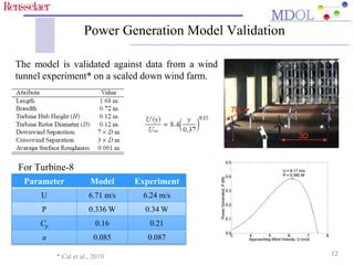
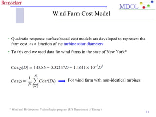
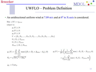
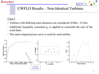
Optimizing the Unrestricted Placement of Turbines of Differing 
Rotor Diameters in a Wind Farm for Maximum Power 
Generation 
Souma Chowdhury*, Achille Messac#, Jie Zhang*, Luciano Castillo*, and 
Jose Lebron* 
* Rensselaer Polytechnic Institute, Department of Mechanical, Aerospace, and Nuclear Engineering 
# Syracuse University, Department of Mechanical and Aerospace Engineering 
ASME 2010 International Design Engineering Technical Conferences (IDETC) 
and Computers and Information in Engineering Conference (CIE) 
August 15-18, 2010 
Montreal, Quebec, Canada
Presentation Outline 
 Motivation and technical background 
 Objectives of this paper 
 UnrestrictedWind Farm Layout Optimization (UWFLO) framework 
 Validation of the power generation model 
 Application of UWFLO to experimental scale wind farm design 
 Concluding Remarks 
2
Motivation 
 The net power generated by a wind farm is negatively affected by the wake 
effects. 
 The reduction in the farm efficiency can be offset by optimal planning of the 
farm layout. 
 A combination of different types of turbines might have the potential to 
improve both the power generation capacity and the economy of a wind farm. 
www.prairieroots.org 3
Wind Farm Optimization 
4 
• Currently wind energy contributes 2% of worldwide electricity consumption. 
• Planned increase in USA by 2030 – 10 fold. 
• Advancing wind energy would require optimal wind farm design strategies. 
Wake effects lead to significant losses in the 
energy available from wind. The 
corresponding critical aspects in optimal 
wind farm design are (not limited to) 
 Farm layout 
 Types of turbines to be installed 
www.wind-watch.org
Existing Wind Farm Optimization Methods 
5 
Grid based approach 
Yields a computationally expensive 
mixed-integer problem for large 
number of turbines 
Array layout approach 
Restricts turbine locating and 
introduces a source of sub-optimality 
• Do not simultaneously optimize the selection of wind turbines 
• Assume a constant induction factor
Research Objectives 
• Develop an analytical wind farm model, which avoids conventional 
restrictions in layout planning. 
• Develop a robust wind farm optimization framework using the power 
generation model, a cost model, and the Particle Swarm Optimization 
(PSO) algorithm. 
• Investigate the potential of using a combination of different types of 
turbines within the scope of layout optimization. 
6
Basic Components of the UWFLO Framework 
Power Generation Model 
 Develops a turbine influence matrix based on the wake effects 
 Considers a variable induction factor and partial wake-rotor overlap 
 Determines the net power generated by the wind farm 
Optimization Framework 
 Implements a wind farm cost model 
 Simultaneously optimizes the selection of differing types of turbines 
 Maximizes the net power generation using the PSO algorithm 
7
UWFLO Power Generation Model 
• The flow pattern inside a wind farm is complex, primarily due to the wake 
effects and the highly turbulent flow. 
• Rotor averaged velocity is determined from the flow profile* 
• Step 1 
Transformed co-ordinates are evaluated 
based on wind direction 
8 
x X 
y Y 
   cos   sin 
 
   
       
   sin  cos 
 
   
i i 
i i 
* Cal et al., 2010
Mutual Influence of Turbines 
• Step 2 
An influence matrix is defined as 
where Turbine-i influences Turbine-j if 
• Step 3 
  
 
j wake ij 
The turbines are ranked in the increasing order of their x-coordinate. Power 
generated by turbines is calculated in the increasing order of their rank. 
9 
1 if Turbine- influences Turbine- 
0 if there is no mutual influence 
ij 
i j 
M j i 
  
 
 
, 0 & 
2 2 
ij ij 
D D 
x  y  
• Step 4 
Power Generated by the Wind Farm 
Effective velocity of wind approaching Turbine-j:* 
The power generated by turbine-j: 
• Step 5 
Coefficient of power 
Power generated by the farm: Farm Efficiency: 
Power generated by 
a standalone turbine 
* Katic et al., 1986 10
Wake Model 
UWFLO uses Frandsen’s wake model*, which calculates the diameter of the 
growing wake and the wake velocity as: 
Wake spreading constant 
However, UWFLO has the flexibility to use any standard wake model. 
11 
* Frandsen et al., 2006
Power Generation Model Validation 
The model is validated against data from a wind 
tunnel experiment* on a scaled down wind farm. 
12 
For Turbine-8 
Parameter Model Experiment 
U 6.71 m/s 6.24 m/s 
P 0.336 W 0.34 W 
Cp 0.16 0.21 
a 0.085 0.087 
* Cal et al., 2010
Wind Farm Cost Model 
• Quadratic response surface based cost models are developed to represent the 
farm cost, as a function of the turbine rotor diameters. 
• To this end we used data for wind farms in the state of New York* 
For wind farm with non-identical turbines 
13 
* Wind and Hydropower Technologies program (US Department of Energy)
Particle Swarm Optimization (PSO) 
Swarm Motion* 
t  1 t t 
 
1 
i i i 
t t t t 
i i l i i g g i 
x x v 
v  v  r p x  r p x 
    
1 
1 2 
 
  
     
Solution Comparison 
The constraint dominance principle** 
is used. 
PSO can appropriately address the 
non-linearity and the multi-modality of 
the wind farm model. 
14 
* Kennedy and Eberhart, 1985 
** Deb et al., 2002
UWFLO – Problem Definition 
• An unidirectional uniform wind at 7.09 m/s and at 0o to X-axis is considered. 
15
16 
UWFLO – Realistic Power Curve 
Case 1 (Case 3 in the paper) 
• Identical turbines, with rotor diameter = 0.12m, is considered here. 
• Modified power curve: The power generated is assumed to remain constant 
at the rated power (0.385W) for U > Rated speed (6.17m/s)
UWFLO Results – Non-Identical Turbines 
17 
Case 2 
• Turbines with differing rotor diameters are considered: 0.08m – 0.16m. 
• Additional inequality constraint g3 is applied to constraint the cost of the 
wind farm. 
• The same original power curve is used for each turbine. 
Number of Function Evaluations 
Objective Function, f 
5000 10000 15000 20000 25000 
1.05 
1.00 
0.95 
0.90 
0.85 
0.80 
0.75 
1 2 
3 
4 
5 
6 
7 
8 
9 
X - coordinate 
Y - coordinate 
0.0 0.5 1.0 1.5 
1.0 
0.5 
0.0 
-0.5 
Turbine Number 
D (m) 
0 1 2 3 4 5 6 7 8 9 10 
0.16 
0.14 
0.12 
0.1 
0.08 
Incoming 
Wind Speed
Concluding Remarks 
 The proposed UWFLO technique avoids limiting assumptions, regarding the 
farm layout and choice of wind turbines. 
 Reasonable agreement is obtained between the UWFLO model and the 
corresponding experimental data. 
 Layout optimization with identical turbines produced a 30% increase in farm 
efficiency compared to the 3x3 array layout. 
 The use of turbines with differing rotor diameters has the potential to increase 
the farm efficiency significantly (43% compared to the array layout). 
18
Future Work 
 Current research is investigating the effects of other critical factors in 
wind farm planning; namely the number of turbines and the farm size. 
 A recently developed mixed-discrete optimization methodology is being 
implemented to appropriately represent the use of non-identical turbines. 
 Future research will also consider the variability of the speed and 
direction of wind, in the case of commercial wind farms. 
19
Selected References 
1. World Wind Energy Report 2008. Bonn, Germany, February 2009. 
2. Katic, I., Hojstrup, J., and Jensen, N. O. A Simple Model for Cluster Efficiency. In Proceedings of European 
Wind Energy Conference and Exhibition (Rome, Italy 1986). 
3. Frandsen, S., Barthelmie, R., Pryor, S, Rathmann, O, Larsen, S, Hojstrup, J, and Thogersen, M. Analytical 
Modeling of Wind Speed Deficit in Large Offshore Wind Farms. Wind energy, 9, 1-2 (2006), 39-53. 
4. Grady, S. A., Hussaini, M. Y., and Abdullah, M. M. Placement of Wind Turbines Using Genetic Algorithms. 
Renewable Energy, 30, 2 (February 2005). 
5. Sisbot, S., Turgut, O., Tunc, M., and Camdali, U. Optimal positioning of Wind Turbines on Gökçeada Using 
Multi-objective Genetic Algorithm. Wind Energy (2009). 
6. Mosetti, G., Poloni, C., and Diviacco, B. Optimization of Wind Turbine Positioning in Large Wind Farms by 
Means of a Genetic Algorithm. Journal of Wind Engineering and Industrial Aerodynamics, 54, 1 (January 
1994), 105-116. 
7. Kennedy, J. and Eberhart, R. C. Particle Swarm Optimization. In Proceedings of the 1995 IEEE International 
Conference on Neural Networks ( 1995), 1942-1948. 
8. Cal, R. B., Lebron, J., Kang, H.S., Meneveau, C., and Castillo, L., “Experimental study of the horizontally 
averaged flow structure in a model wind-turbine array boundary layer”, Journal of Renewable and 
Sustainable Energy, 2, 1 (2010). 
9. Lebron, J., Castillo, Cal, R. B., Kang, H. S., and Meneveau, C., 2010, “Interaction Between a Wind Turbine 
Array and a Turbulent Boundary Layer,” Proceeding 49th AIAA Aerospace Sciences Meeting including the 
New Horizons Forum and Aerospace Exposition, January 4-9. 
20
Acknowledgement 
21 
Thank you
Questions 
or 
Comments 
22

WFO_IDETC_2011_Souma

  • 1.
    Optimizing the UnrestrictedPlacement of Turbines of Differing Rotor Diameters in a Wind Farm for Maximum Power Generation Souma Chowdhury*, Achille Messac#, Jie Zhang*, Luciano Castillo*, and Jose Lebron* * Rensselaer Polytechnic Institute, Department of Mechanical, Aerospace, and Nuclear Engineering # Syracuse University, Department of Mechanical and Aerospace Engineering ASME 2010 International Design Engineering Technical Conferences (IDETC) and Computers and Information in Engineering Conference (CIE) August 15-18, 2010 Montreal, Quebec, Canada
  • 2.
    Presentation Outline Motivation and technical background  Objectives of this paper  UnrestrictedWind Farm Layout Optimization (UWFLO) framework  Validation of the power generation model  Application of UWFLO to experimental scale wind farm design  Concluding Remarks 2
  • 3.
    Motivation  Thenet power generated by a wind farm is negatively affected by the wake effects.  The reduction in the farm efficiency can be offset by optimal planning of the farm layout.  A combination of different types of turbines might have the potential to improve both the power generation capacity and the economy of a wind farm. www.prairieroots.org 3
  • 4.
    Wind Farm Optimization 4 • Currently wind energy contributes 2% of worldwide electricity consumption. • Planned increase in USA by 2030 – 10 fold. • Advancing wind energy would require optimal wind farm design strategies. Wake effects lead to significant losses in the energy available from wind. The corresponding critical aspects in optimal wind farm design are (not limited to)  Farm layout  Types of turbines to be installed www.wind-watch.org
  • 5.
    Existing Wind FarmOptimization Methods 5 Grid based approach Yields a computationally expensive mixed-integer problem for large number of turbines Array layout approach Restricts turbine locating and introduces a source of sub-optimality • Do not simultaneously optimize the selection of wind turbines • Assume a constant induction factor
  • 6.
    Research Objectives •Develop an analytical wind farm model, which avoids conventional restrictions in layout planning. • Develop a robust wind farm optimization framework using the power generation model, a cost model, and the Particle Swarm Optimization (PSO) algorithm. • Investigate the potential of using a combination of different types of turbines within the scope of layout optimization. 6
  • 7.
    Basic Components ofthe UWFLO Framework Power Generation Model  Develops a turbine influence matrix based on the wake effects  Considers a variable induction factor and partial wake-rotor overlap  Determines the net power generated by the wind farm Optimization Framework  Implements a wind farm cost model  Simultaneously optimizes the selection of differing types of turbines  Maximizes the net power generation using the PSO algorithm 7
  • 8.
    UWFLO Power GenerationModel • The flow pattern inside a wind farm is complex, primarily due to the wake effects and the highly turbulent flow. • Rotor averaged velocity is determined from the flow profile* • Step 1 Transformed co-ordinates are evaluated based on wind direction 8 x X y Y    cos   sin               sin  cos     i i i i * Cal et al., 2010
  • 9.
    Mutual Influence ofTurbines • Step 2 An influence matrix is defined as where Turbine-i influences Turbine-j if • Step 3    j wake ij The turbines are ranked in the increasing order of their x-coordinate. Power generated by turbines is calculated in the increasing order of their rank. 9 1 if Turbine- influences Turbine- 1 if Turbine- influences Turbine- 0 if there is no mutual influence ij i j M j i     , 0 & 2 2 ij ij D D x  y  
  • 10.
    • Step 4 Power Generated by the Wind Farm Effective velocity of wind approaching Turbine-j:* The power generated by turbine-j: • Step 5 Coefficient of power Power generated by the farm: Farm Efficiency: Power generated by a standalone turbine * Katic et al., 1986 10
  • 11.
    Wake Model UWFLOuses Frandsen’s wake model*, which calculates the diameter of the growing wake and the wake velocity as: Wake spreading constant However, UWFLO has the flexibility to use any standard wake model. 11 * Frandsen et al., 2006
  • 12.
    Power Generation ModelValidation The model is validated against data from a wind tunnel experiment* on a scaled down wind farm. 12 For Turbine-8 Parameter Model Experiment U 6.71 m/s 6.24 m/s P 0.336 W 0.34 W Cp 0.16 0.21 a 0.085 0.087 * Cal et al., 2010
  • 13.
    Wind Farm CostModel • Quadratic response surface based cost models are developed to represent the farm cost, as a function of the turbine rotor diameters. • To this end we used data for wind farms in the state of New York* For wind farm with non-identical turbines 13 * Wind and Hydropower Technologies program (US Department of Energy)
  • 14.
    Particle Swarm Optimization(PSO) Swarm Motion* t  1 t t  1 i i i t t t t i i l i i g g i x x v v  v  r p x  r p x     1 1 2         Solution Comparison The constraint dominance principle** is used. PSO can appropriately address the non-linearity and the multi-modality of the wind farm model. 14 * Kennedy and Eberhart, 1985 ** Deb et al., 2002
  • 15.
    UWFLO – ProblemDefinition • An unidirectional uniform wind at 7.09 m/s and at 0o to X-axis is considered. 15
  • 16.
    16 UWFLO –Realistic Power Curve Case 1 (Case 3 in the paper) • Identical turbines, with rotor diameter = 0.12m, is considered here. • Modified power curve: The power generated is assumed to remain constant at the rated power (0.385W) for U > Rated speed (6.17m/s)
  • 17.
    UWFLO Results –Non-Identical Turbines 17 Case 2 • Turbines with differing rotor diameters are considered: 0.08m – 0.16m. • Additional inequality constraint g3 is applied to constraint the cost of the wind farm. • The same original power curve is used for each turbine. Number of Function Evaluations Objective Function, f 5000 10000 15000 20000 25000 1.05 1.00 0.95 0.90 0.85 0.80 0.75 1 2 3 4 5 6 7 8 9 X - coordinate Y - coordinate 0.0 0.5 1.0 1.5 1.0 0.5 0.0 -0.5 Turbine Number D (m) 0 1 2 3 4 5 6 7 8 9 10 0.16 0.14 0.12 0.1 0.08 Incoming Wind Speed
  • 18.
    Concluding Remarks The proposed UWFLO technique avoids limiting assumptions, regarding the farm layout and choice of wind turbines.  Reasonable agreement is obtained between the UWFLO model and the corresponding experimental data.  Layout optimization with identical turbines produced a 30% increase in farm efficiency compared to the 3x3 array layout.  The use of turbines with differing rotor diameters has the potential to increase the farm efficiency significantly (43% compared to the array layout). 18
  • 19.
    Future Work Current research is investigating the effects of other critical factors in wind farm planning; namely the number of turbines and the farm size.  A recently developed mixed-discrete optimization methodology is being implemented to appropriately represent the use of non-identical turbines.  Future research will also consider the variability of the speed and direction of wind, in the case of commercial wind farms. 19
  • 20.
    Selected References 1.World Wind Energy Report 2008. Bonn, Germany, February 2009. 2. Katic, I., Hojstrup, J., and Jensen, N. O. A Simple Model for Cluster Efficiency. In Proceedings of European Wind Energy Conference and Exhibition (Rome, Italy 1986). 3. Frandsen, S., Barthelmie, R., Pryor, S, Rathmann, O, Larsen, S, Hojstrup, J, and Thogersen, M. Analytical Modeling of Wind Speed Deficit in Large Offshore Wind Farms. Wind energy, 9, 1-2 (2006), 39-53. 4. Grady, S. A., Hussaini, M. Y., and Abdullah, M. M. Placement of Wind Turbines Using Genetic Algorithms. Renewable Energy, 30, 2 (February 2005). 5. Sisbot, S., Turgut, O., Tunc, M., and Camdali, U. Optimal positioning of Wind Turbines on Gökçeada Using Multi-objective Genetic Algorithm. Wind Energy (2009). 6. Mosetti, G., Poloni, C., and Diviacco, B. Optimization of Wind Turbine Positioning in Large Wind Farms by Means of a Genetic Algorithm. Journal of Wind Engineering and Industrial Aerodynamics, 54, 1 (January 1994), 105-116. 7. Kennedy, J. and Eberhart, R. C. Particle Swarm Optimization. In Proceedings of the 1995 IEEE International Conference on Neural Networks ( 1995), 1942-1948. 8. Cal, R. B., Lebron, J., Kang, H.S., Meneveau, C., and Castillo, L., “Experimental study of the horizontally averaged flow structure in a model wind-turbine array boundary layer”, Journal of Renewable and Sustainable Energy, 2, 1 (2010). 9. Lebron, J., Castillo, Cal, R. B., Kang, H. S., and Meneveau, C., 2010, “Interaction Between a Wind Turbine Array and a Turbulent Boundary Layer,” Proceeding 49th AIAA Aerospace Sciences Meeting including the New Horizons Forum and Aerospace Exposition, January 4-9. 20
  • 21.
  • 22.