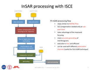
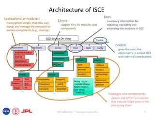
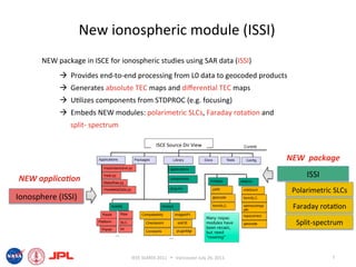
- The document describes techniques for estimating ionospheric effects from SAR data using the ISCE software tool.
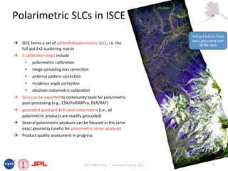
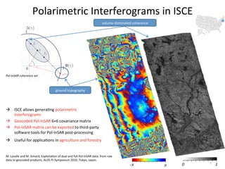
- ISCE has new capabilities for processing polarimetric and polarimetric interferometric SAR (Pol-InSAR) data to estimate parameters like Faraday rotation and total electron content (TEC).
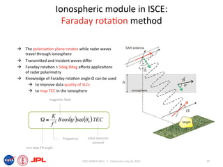
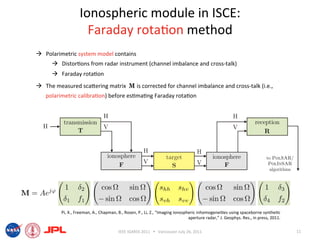
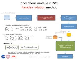
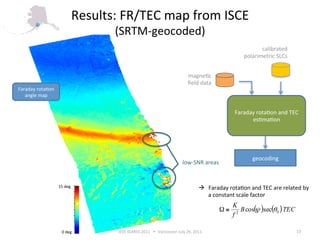
- The ionospheric module in ISCE uses the Faraday rotation method to model calibrated polarimetric SLCs and estimate Faraday rotation angles and TEC from the data.